Báo cáo hóa học: " Audio watermarking robust against D/A and A/D conversions" pptx
Bạn đang xem bản rút gọn của tài liệu. Xem và tải ngay bản đầy đủ của tài liệu tại đây (672.82 KB, 14 trang )
RESEARCH Open Access
Audio watermarking robust against D/A and A/D
conversions
Shijun Xiang
1,2
Abstract
Digital audio watermarking robust against digital-to-analog (D/A) and analog-to-digital (A/D) conversions is an
important issue. In a number of watermark application scenarios, D/A and A/D conversions are involved. In this
article, we first investigate the degradation due to DA/AD conversions via sound cards, which can be decomposed
into volume change, additional noise, and time-scale modification (TSM). Then, we propose a solution for DA/AD
conversions by considering the effect of the volume change, additional noise and TSM. For the volume change,
we introduce relation-based watermarking method by modifying groups of the energy relation of three adjacent
DWT coefficient sections. For the additional noise, we pick up the lowest-frequency coefficients for watermarking.
For the TSM, the synchronization technique (with synchronization codes and an interpolation processing operation)
is exploited. Simulation tests show the proposed audio watermarking algorithm provides a satisfactory performance
to DA/AD conversions and those common audio processing manipulations.
Keywords: Audio watermarking D/A and A/D conversions, Synchronization, Magnitude distortion, Time scaling,
Wavelet transform
Introduction
With the development of the Internet, illegal copying of
digital audio has become more w idespread. As a tradi-
tional data protection method, encryption cannot be
applied in that the content must be played back in the
original style. There is a potential solution to the pro-
blem that is to mark the audio signal with an impercep-
tible and robust watermark [1]-[3].
In the past 10 years, attacks against audio watermark-
ing are becoming more and more complicated with the
development of watermarking technique. According to
International Federation of the Phonographic Industry
(IFPI) [4], in a desired audio watermarking system, the
watermark should be robusttocontent-preserving
attacks including desync hronization attacks and audio
processing operations. From the audio watermarking
point of view, desynchronizaiton attacks (such as crop-
ping and time-scale modification ) mainly introduce syn-
chronization problems between encoder and decoder.
The watermark is still present, but the detector is no
longer able to extract it. Different from desynchroniza-
tion attacks, audio processing operations (including
requantization, the additio n of noises, MP3 lossy com-
pression, and low-pass filtering operations) do not cause
synchronization problems, but w ill reduce the water-
mark energy.
The problem of audio watermarking against common
audio processing operations can be solved by embedding
the watermark in the frequency domain instead of in the
time domain. The time domain-based solutions (such as
LSB schemes [5] and echo hiding [6]) usually have a low
computational cost but somewhat sensitive to additive
noises, while the frequency d omain watermarking meth-
ods provide a satisfactory resistance to audio processing
operations by watermarking low-frequency component
ofthesignal.Therearethreedominantfrequency
domain watermarking methods: Discrete Fourier Trans-
form (DFT) based [7], [8], Discrete Wavelet Transform
(DWT) based [9], [10], and Discrete Cosine Transform
(DCT) based [11]. They have shown satisfactory robust-
ness performance to MP3 lossy compression, additive
noise and low-pass filtering operations.
In the literature, there are a few algorithms aiming at
solving desynchronizati on attacks. For cropping (such as
Correspondence:
1
School of Information Science and Technology, Jinan University,
Guangzhou, China
Full list of author information is available at the end of the article
Xiang EURASIP Journal on Advances in Signal Processing 2011, 2011:3
/>© 2011 Xiang; licensee Springer. This is an Open Access article distributed under the terms of the Creati ve Commons Attribution
License ( /licenses/by/2.0), which permits unrestricted use, distribution, and reproduction in any medium,
provided the original work is properly cited.
editing, signal interruption in wireless transmission, and
data packet loss in IP network), researchers repeatedly
embedded a template into different regions of the signal
[9]-[13], such as synchronization code-based self syn-
chronization methods [9]-[11] and the use of multiple
redundant watermarks [14], [15]. Though the template
based watermarking can combat cropping but cannot
cope with TSM operations, even for the scaling amount
of ± 1%. In the audio watermarking c ommunity, there
exist some TSM-resilient watermarking strategies, such
as peak points based [16]-[18] and recently reported his-
togram based [19], [20]. In [ 16], a bit can be hidden by
quantizing the length of each two adjacent peak points.
In [17], the watermark was repeatedly embedded into
the edges of an audio signal by viewing pitch-invari ant
TSM as a special form of random cropping, removing
and adding som e portions of the audio signal while pre-
serving the pitch. In [18], the invariance of dyadic wave-
let transform to linear scaling was exploited to design
audio watermarking by modulating the wave shape. The
three dominant peak point-based watermarking methods
are resistant to TSM because the peaks can still be
detected before and after a TSM operation. The histo-
gram-based methods [19], [20] are robust to TSM
operations because the shape of histogram of an audio
signal is provably invariant to temporal linear scaling. In
addition, the histogram is independent of a sample’s
position in the time domain.
We can see that the above existing audio watermark-
ing algorithms only consider the watermark attacks in
the digital environment. The effect of the analog trans-
mission channel via DA/AD conversions is little men-
tioned. Toward this direction, in this article, we propose
a solution for DA/AD conversions by considering the
degradation of the conversions (which is empirically
proved to be a c ombinat ion of volume change, additive
noise and a small TSM). First, the relation-based water-
marking strategy is introduced for the volume change
1
by modifying the relative energy relations among groups
of three consecutive DWT coefficient sections. Secondly,
the watermark is embedding in the low-frequency sub-
band against the addition noise. Thirdly, synchronization
strategy via synchronization code searching followed by
an interpolation processing operation is applying for the
TSM. Experimental results have demonstrated that the
proposed watermarking algorithm is robust to the DA/
AD conversions, also resistant to common audio proces-
sing manipulations and mo st of the attacks in StirMark
Benchmark for Audio [21].
The rest of this article is organized as follows. Section
“DA/AD conversions” analyzes watermark transmission
channels and then investigates the characteristics of the
DA/AD distortion in experimental way. This is followed
by our proposed watermark embedding and detecting
strategies, performance analysis, experimental results
regarding the imperceptivity and robustness. Finally, we
draw the conclusions.
DA/AD conversions
The watermark against DA/AD conversions is an impor-
tant issue [8]. It is worth noting from the previous algo-
rithms that few audio watermarking algorithms consider
those possible analog transmission environments, which
involve DA/AD conversions.
Watermark transmission environments
The digital audio can be transmitted in various environ-
ments in practical applications. Some possible scenario s
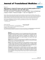
are described in [8], [22], as shown in Figure 1. From
this figure, transmission environments of an audio
watermark may be concluded as follows.
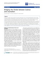
The first signal is transmitte d through the environ-
ment in such a way that is unmodified, shown in Figure
1a.Asaresult,thephaseandtheamplitudeare
unchanged. In Figure 1b, the signal is re-sampled with a
higher or lower sampling rate. The amplitude and the
phase are left unchanged, but the temporal characteris-
tics are changed. The third case, in Figure 1c, is to con-
vert the signal and transmit it in the analog form. In
this case, even if the analog line is considered clear, the
amplitude, the phase, and the sampling rate may be
changed. The last case (see Figure 1d) is when the envir-
onment is not clear, the signal being subjected to non-
linear transformations, resulting in phase changes,
amplitude changes, echoes, etc. In the term of signal
processing, watermark is a weak signal embedded into a
strong background like the digital audio, so the variety
of carriers will influence the watermark detection
directly. Therefore, the attacks that audio wate rmark is
suffering from is similar to the cover signal. In Figure
1a, audio watermark is not infected; In Figure 1b, re-
sampling attacked the audio watermarking, which had
been settled by many algorithms; even it is considered
no noise corruption in Figure 1c, audio watermarking
Figure 1 Transmission environments of digital audio.
Xiang EURASIP Journal on Advances in Signal Processing 2011, 2011:3
/>Page 2 of 14
still suffer from the effects of DA/AD; F igure 1d shows
the worst environment, where the watermark is attacked
by various interferences simultaneity.
In audio watermarking community, researchers have
paid more attention to the effect of the first and second
transmission channels (the corresponding watermark
attacks include common audio processing and desyn-
chronization operations). However, few researchers con-
sider the third and fourth transmission environments. In
many applications of audio watermarkin g [23]-[26],
where the watermark is required to be transmitted via
analog environments. For instances, secret data is pro-
posed to be transmitted via analo g telephone channel in
[24], and a hidden watermark signal is used to identify
pirated music for broadcast music monitoring [23], [25]
and live concert performance [26]. In these existing
works [12], [23]-[29], though the issue of the watermark
against DA/AD conversions has been mentioned, the
robustness performance is unsatisfactory. In addition,
there are no technical descriptions on how to design a
watermark for DA/AD conversions. Specifically, none of
them have reported how to c ope with the influence
caused by DA/AD conversions in detail.
In this study, our motivation is to design an audio
watermarking algorithm against the third transmission
channel, i.e., we consider the effect of DA/AD conver-
sions on the watermark. From the existing works [8],
[22], [29] and the findings in this article, it is worth not-
ing that DA/AD conversions may distort an audio signal
from two aspects: (1) serious magnitude distortion due
tothechangeofplaybackvolumeandadditivenoise
corruption, (2) a small amount of TSM. This indicates
that an effective audio watermarking algorithm for DA/
AD conversions should be robust to the attack com-
bined with TSM, volume change (the samples in magni-
tude are scaled with the same factor) and addi tive noise.
This is more complicated th an only performing an inde-
pendent TSM or audio processing operation. This
explains why a watermark’ sresistancetotheDA/AD
hasbeenconsideredasanimportantissue[8].The
effect of DA/AD conversions on an audio signal is
described as follows.
Test scenario
In order to investigate the effect caused by the DA/AD
conversions on audio signals, we have designed and
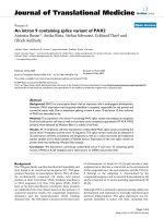
used the following test mo del, as shown in Figure 2. A
digital audio file is converted to an analog signal by a
sound card, which is output from Line-out to Line-in for
re-sampling. Usually, the DA/AD conversions are imple-
mented using the same sound card for playing back and
recording. Here, we use a cable line for the link between
line-out and line-in. Thus, the distortion is mainly from
the DA/AD conversions since the cable line may be
considered clear.
Weadoptasetof16-bitsignedmonoaudiofilesin
the WAVE format as test clips. These files are sampled
at 8, 11.025, 16, 22.05, 32, 44.1, 48, 96, and 128 kHz to
investigate the eff ect of sampling frequency. All a udio
files are played back with the software Window Media
Player 9.0. The DA/AD distorted audio signals are
recorded using the audio editing tool Cool Edit V2.1.
Effects of DA/AD conversions on audio signals
During the DA/AD conversions, digital audio signal will
suffer from the following distortions [29]:
1) Noise produced by soundcards during DA
conversion;
2) Modification of audio signal energy and noise
energy;
3) Noise in analog channel;
4) Noise prod uced by soundcard during AD c onver-
sion including quantization distortion.
The above observations show that a digital audio clip
will be distorted under the DA/AD conversions due to
wave magnitude distortion including noise corruption
and modification of audio signal energy.
In this art icle, we are observing from extensive testing
that the DA/AD conversions may cause the shift of
samples in the time domain, which can be considered as
a TSM operation with a small scaling amount. As a
result, the effect of the DA/AD conversions can be
further represented as wave magnitude distortion and
time scale modification.
Temporal linear scaling
Based on the test model shown in Figure 2, numerous
different soundcards are employed to test different
audio files with different sampling frequencies. The
time-scale modification during the DA/AD conversions
for two sampling rates of audio files are reported in
Table 1. When applying other sampling frequencies of
test clips, we can have similar observations. The card
Sound Blaster Live5.1 is a consumer grade of sound
board, ICON StudioPro7.1 is a professional o ne, while
6SHDNHUSRUW
RIVRXQGFDUG
'$
&DEOH
/LQH
LQSRUWRI
VRXQGFDUG
$'
'LJLWDO
3OD\LQJEDFN
DXGLRVLJQDOV
5HFRUGLQJ
DXGLRVLJQDOV
I
)
)
I
$QDORJ
$QDORJ
'LJLWDO
Figure 2 Simulation model for the DA/AD conversions.
Xiang EURASIP Journal on Advances in Signal Processing 2011, 2011:3
/>Page 3 of 14
Realtek AC’97 audio for VIA (R) Audio controller, Audio
2000 PCI,andSoundMAX Digital Audio are common
PC sound cards. From Table 1, it is wo rth noting that
during the DA/AD conversions, the sample number is
modified linearly, described as follows:
1) The scaling factor varies with diffe rent soundcards,
i.e.,duringtheDA/ADconversions,differentperfor-
manc es of soundcar ds will cause different amplitudes of
time-scale modifications.
2) The sampling frequencies of an audio file have an
effect on the amplitude of the scaling factor. With the
same soundcard, the scaling distortion is also relative to
the sampling rate of test clips.
We can see from the table that when keeping the
soundcard and the sampling rate of audio files
unchanged, the scaling factor is linear to the duration of
audio clips. Take the soundcard Blaster Live5.1 as an
example, each 10 s of duration at 44.1 kHz will lose six
sample (expressed as -6 in the table). Another example
is that for the RealTex AC’97, a file of length 10 s at 8
kHz will add five samples (expressed as +5 in the table).
Empirically, the time scaling in amplitude is usually
between -0.005 and 0.005. We also use two different
soundcards for the DA/AD testing (one for the D/A
processing while another for the A/D conversion), and
the simulation results are similar.
Wave magnitude distortion
Under the DA/AD conversions, anot her kind of degra-
dation on the digital audio files is wave magnitude dis-
tortion, which can be considered as a combination of
volume change and additive noise, as reported in [29].
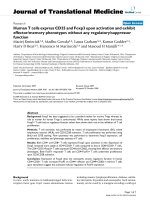
In our experiments, we observed that the samples in
amplitude may be distorted during the DA/AD conver-
sions, and the distortion relies on the volume played
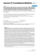
back, and the performance of the soundcard. Figures 3
and 4 have the same scaling in both horizontal and ver-
tical axis in displaying waves of the original clip and the
corresponding recorded one by the Blaster Live5.1
soundcard. Comparing with the original one, the
recorded audio file in energy is obviously reduced. Here,
we use the SNR standard to measure the wave magni-
tude distortion. Denote the original file by F wi th N
1
samples in number, the corresponding distorted one by
F
2
samples. The SNR value between the two fil es can be
expressed as
SNR = −10 log
10
N
i−1
[f (i) − f
(i)]
2
N
i−1
[f (i)]
2
, f
(i)=f
(i)·
N
i−1
|f (i)|
N
i−1
|f
(i)|
, N =min{N
1
, N
2
}
,
(1)
where F’’ is the energy-normalized version of F’ by
referring to F with the consideration of signal energy
modificat ion in the DA/AD processing. f(i), f’(i) and f’’(i)
are, respectively, the value of the ith point in F, F’,and
F’’.WhenN
1
≠ N
2
, it reflects the existence of the time-
scaling during the DA/AD conversions. In this case, we
need to length-normalize F’’ to generate
F
1
which has
the same length as the original file F. After the length-
normalization operation, the SNR value between F” and
F
1
can be computed. Here, the length-normalization
step is an interpolation processing operation. The
detailed information regarding the interpolation step is
Table 1 The modification of the sample amount for test clips at sampling rates of 8 and 44
Sampling rates Time (s) Blaster Live5.1 Realtek AC’97 Audio 2000 PCI Studio Pro 7.1 SoundMAX Digital Audio
10 -1 +5 +102 -70 +1
20 -2 +10 +204 -140 +2
8 kHz 30 -3 +15 +306 -210 +3
40 -4 +20 +408 -280 +4
50 -5 +25 +510 -350 +5
10 -6 +4 0 0 +2
20 -12 +8 0 0 +4
44:1 kHz 30 -18 +12 0 0 +6
40 -24 +16 0 0 +8
50 -30 +20 0 0 +10
Figure 3 The original clip.
Xiang EURASIP Journal on Advances in Signal Processing 2011, 2011:3
/>Page 4 of 14
giveninsection“ Resynchronization and interpolation
operation.”
For experimental description, we choose the sound-
card Sound Blaster Live5 .1 and an audio file sampled at
44.1 kHz to dem onstrate the wave magnitude distortion
in the test model in Figure 2. The SNR values of F ver-
sus F” and
F
1
are illustrated in Figures 5 and 6,
respectively.
We can see from Figure 5 that the SNR values (before
the length-normalization operation) decrease quickly
due to the fact that the scaling will shift samples in loca-
tion. It indicates the effect of the time scaling in the
DA/AD conversions. In Figure 6, the SNR values (after
the length-normalization operation) remain stable, indi-
cating that the length-normalization operation proposed
in this article can effectively eliminate the effect of the
time scaling. The SNR values in Figure 6 are between
15 and 30 dB, which demonstrate the existence of the
additive noise.
Effects of DA/AD conversions on audio watermarking
From the above experimental analysis, we conclude that
the DA/AD distortion can be represented as the combi-
nation of time scaling modification and wave magnitude
distortion. From the signal processing point of view, a
watermark can be taken as a weak signal added onto a
cover-signal (such as a digital audio clip or an image
file). Therefore, any distortion on the cover-signal will
be able to influence the detection of the insert ed water-
mark.Fromthisangle,wecanseethatanaudiowater-
mark under the DA/AD conversions will be distorted
due to (1) time scaling modification (that will int roduce
synchronization problem due to the shifting of samples
in the time domain) and (2) wave magnitude distortion
(that will reduce watermark energy due to signal energy
modification followed by an additive noise). Mathemati-
cally speaking, the effect of the D A/AD conversions on
audio watermarking can be formulated as,
f
(i)=λ · f
i
α
+ η
,
(2)
where a is a time scaling factor in the DA/AD, l is an
amplitude scaling factor, and h is an additive noise dis-
tortion on the sample value f(i). f’(i) is the value at point
i after the conversions. When a is not an integer,
f
i
α
is interpolated with the nearest samples. Via
Figure 4 The distorted clip due to the DA/AD.
7LPH
V
6
15
GE
615RI)DQG)
GLDORJZDY
PDUFKZDY
GUXPZDY
IOXWHZDY
Figure 5 The SNR value before the length-normalization
operation.
7LP H
V
615GE
615RI)DQG)
GLDORJZDY
PDUFKZDY
GUXPZDY
IOXWHZDY
Figure 6 The SNR value after the length-normalization
operation.
Xiang EURASIP Journal on Advances in Signal Processing 2011, 2011:3
/>Page 5 of 14
extensive testing, we observed that the parameter a is in
the range [-0.005, 0.005] while the l value is in [0.5, 2].
For different soundcards, the h value is different, mean-
ing different powers of additive noise.
The above distortional model is concluded in e xperi-
mental way by using soundcards via line-out/line-in.
Another possible situation is that the signal is re cording
using a microphone instead of a line-in signal (called
lineout/mic rophone-i n). In this case, we need to co n-
sid er the characteristics of microphone and background
noise.
Watermark insertion
In this part, we present an audio watermarking strategy
to cope with the DA/AD co nversions by considering the
TSM, signal energy change and additive noise di stortion
as formulated in Equation 2. Our strategy includes three
main steps:
1) We adopt the relation-based water marking strateg y
so that the watermark is resistant to the energy change
of audio signals in the DA/AD conversions.
2) Consider the additive no ise corruption, the water-
mark is inserted into the lowest frequency subband of
DWT domain.
3) The resynchronization ste p via synchronization
codes and an interpolation operation is designed for the
TSM.
Embedding framework
The main idea of the proposed embedding algorithm is
to split a long audio sequence into many segments for
performing DWT, and then use three adjacent DWT
low-frequency coefficient segments as a group to insert
one synchronization sequence and one watermark (or
part of watermark bits). The embedding block diagram
is plotted in Figure 7.
During the embedding, the watermark is adaptively
embedded by referring to objective difference grade
(ODG) value of the marked audio with the considera-
tion of the human auditory system. The ODG value is
controlledintherange[0,-2]tomakesurethatthe
watermarked clip is imperceptibly similar to the original
one. Suppose that S
1
is the ODG value of the water-
marked audio, S
0
is a predefined one. When S
1
is less
than S
0
, the embedding distortion will be automatically
decreased until S
1
>S
0
. For saving the computational
cost, we compute the ODG value in the DWT domain
instead of in the time domain. In such a way, the com-
putational load can be reduced by saving those unneces-
sary inverse discrete wavelet transform (IDWT)
operations in the embedding. Only when the ODG
value is satisfactory, the IDWT is performed to regener-
ate the watermarked audio.
Embedding strategy
As mentioned above and will be further discussed in the
rest of this article, the proposed embedding algorithm is
conducted in the DWT domain because of its superior-
ity. To hide data robust to modification of audio ampli-
tude, the wate rmark is embedded in the DWT d omain
using the relative relationships among different groups
of the DWT coefficients. It is worth noting that utilizing
the relationships among different audio sample sections
to embed data has been proposed in [12]. However,
what proposed in this article is different from [12].
Instead of embedding in the time domain, we insert the
watermark in the low-frequency sub-band of the DWT
domain to achieve better robustness performance. In the
DWT domain, the ti me-frequen cy localization charac-
teristic of DWT can be exploited to save the computa-
tional load during searching synchronization codes [9],
[10]. Denote a group of three consecutive DWT coeffi-
cient sections by Section _1, Sectio n _2, and Section _3,
as shown in Figure 8. Each section includes L DWT
coe fficients. The energy values of a group of three adja-
cent coefficient sections, denoted by E
1
, E
2
,andE
3
,are
defined as
E
1
=
L
i
=1
|c(i)|, E
2
=
2L
i
=L+1
|c(i)|, E
3
=
3L
i
=2L+1
|c(i)|
,
(3)
where c(i)istheith coefficient in the lowest frequency
subband. The selection of the parameter L is a tradeoff
among the embedding bit rate (capacity), the SNR value
2ULJLQDODXGLR
VLJQDO
6HJPHQWLQJDQG
SHUIRUPLQJ':7IRU
RXUVHJPHQWV
(PEHGGLQJ
,':7
6\QFKURQL]DWLRQ
FRGH
,QIRUPDWLYH
GDWD
:DWHUPDUNHG
DXGLRVLJQDO
2
'
*
6HJPHQWV
OLQNLQJ
Figure 7 Block diagram of watermark insertion.
Xiang EURASIP Journal on Advances in Signal Processing 2011, 2011:3
/>Page 6 of 14
of the watermarked audio (imperceptivity), and the
embedding strengt h (Robustness). Usually, the bigger
section length L, the stronger robustness is obtained. The
differences among E
1
, E
2
, and E
3
can be expressed as
A = E
max
− E
med
B = E
med
− E
min
,
(4)
where E
max
=max{E
1
, E
2
, E
3
}, E
med
=med{E
1
, E
2
, E
3
},
and E
min
= min{E
1
, E
2
, E
3
}. max, med, and min calculate
the maximum, medium, and minimum of E
1
, E
2
, and E
3
,
respectively. A and B stand for their energy differences.
In the proposed strategy, one watermark bit w(i) can
be embedded by modifying the relationships among A,
B and the embedding strength S, as shown in Equation
5:
A − B ≥ S if w(i)=1
B − A ≥ S if w(i)=0
,
(5)
The parameter S is designed as
S =
d ·
3L
i=1
c(i)
3
,
(6)
where d is called as the embedding strength factor. To
resist wave magnitude distortion during the DA/AD
conversions, the d value should be as large as possible
under the constraint of imperceptibility. The parameter
d is first assigned as a predefined value, and then auto-
matically adjusted until the ODG value of the water-
marked audio is satisfied.
In Equation 5, when w(i)is‘1’ and A - B ≥ S or when
w(i)is‘0’ an d B - A ≥ S, there is no operation. Other-
wise, a group of three consecutive DWT coefficient sec-
tions will be adjusted until satisfying A - B ≥ S (for the
bit ‘ 1’ )orB - A ≥ S (for the bit ‘0’ ). The watermark
rules are completed by modifying the correspo nding
DWT coefficients, formulated in Equations 7-12.
When w(i)is‘1’ and A - B <S, we apply the following
rule to modify the three DWT coefficient sections until
satisfying the condition A - B ≥ S:
c
(i)=
⎧
⎪
⎨
⎪
⎩
c(i) · (1 +
|ξ|
E
max
+2E
med
+ E
min
)ifc(i)isusedforE
max
and E
mi
n
c(i) · (1 −
|ξ|
E
mm
+2E
m
ed
+ E
min
)ifc(i)isusedforE
med
,
(7)
where |ξ| = |A - B - S| = S-A+ B = S-E
max
+2E
med
-E
min
due to A-B<S.FromEquation7,wehave
E
med
= E
med
· (1 −
|
ξ
|
E
max
+2E
med
+ E
min
)
,
E
med
= E
med
· (1 −
|ξ|
E
m
a
x
+2E
m
ed
+ E
min
)
,and
E
min
= E
min
· (1 +
|ξ|
E
m
a
x
+2E
m
ed
+ E
min
)
. Here,
E
m
ax
,
E
m
ed
,and
E
min
are supposed to be the maximum, med-
ium, and minimum of the energy values of three coeffi-
cient sections after the embedding. Note that the above
operation for bit ‘1’ may cause
E
m
ed
< E
min
due to the
fact that
E
min
> E
mi
n
, E
min
<E
med
,and
E
m
ed
< E
me
d
.
Such situation will influence the watermark detection.
In order to make sure
E
m
ed
≥ E
mi
n
min after the embed-
ding, we derive that the embedding strength S should
satisfy the following condition:
S ≤
2E
med
E
m
ed
+ E
min
· (E
max
− E
min
)
.
(8)
The detailed proof process is described in Equation 9
E
med
≥ E
min
⇔ E
med
·
1 −
|ξ|
E
max
+2E
med
+ E
min
≥ E
min
·
1+
|ξ|
E
max
+2E
med
+ E
min
⇔ E
med
· (E
max
+2E
med
+ E
min
−|ξ|) ≥ E
min
· (E
max
+2E
med
+ E
min
+ |ξ|)
⇔ E
med
· (2E
max
+2E
min
− S) ≥ E
min
· (4E
med
+ S)
⇔ S · (E
med
+ E
min
) ≤ 2E
med
· (E
max
− E
min
)
⇔ S ≤
2E
med
E
med
+ E
min
· (E
max
− E
min
)·
(9)
Similarly, when w(i)is‘ 0’ an d B - A ≤ S,agroupof
the DWT coefficients are marked as follows:
c
(i)=
⎧
⎪
⎨
⎪
⎩
c(i) · (1 −
|ξ|
E
mm
+2E
med
+ E
min
)ifc(i)isusedforE
max
and E
mi
n
c(i) · (1 +
|ξ|
E
m
a
x
+2E
m
ed
+ E
min
)ifc(i)isusedforE
med
,
(10)
where |ξ|=|B-A-S|=S+A-B=S+E
max
-2E
med
+ E
min
due to B-A<S.A<S. From Equation 10, we
have
E
max
= E
max
· (1 −
|ξ|
E
mm
+2E
m
ed
+ E
min
)
,
E
med
= E
med
· (1 +
|
ξ
|
E
max
+2E
med
+ E
min
)
,and
E
min
= E
min
· (1 −
|ξ|
E
m
a
x
+2E
m
ed
+ E
min
)
.Theabove
equation shows that the embedding operation for water-
marking bit ‘0’ may cause
E
m
ed
> E
ma
x
due to the fact
F
L
L
///
6HFWLRQB
6HFWLRQB
6HFWLRQB
Figure 8 Three consecutive coefficient sections in the lowest frequency subband of DWT domain.
Xiang EURASIP Journal on Advances in Signal Processing 2011, 2011:3
/>Page 7 of 14
that E
max
decreases while E
med
increases. To make sure
E
max
≥ E
m
ed
after watermarking, the S value is designed
to satisfy:
S ≤
2E
med
E
m
ed
+ E
m
a
x
· (E
max
− E
min
)
.
(11)
The detailed proof process is described in Equation
12:
E
max
≥ E
med
⇔ E
max
· (1 −
|ξ|
E
max
+2E
med
+ E
min
) ≥ E
med
· (1 +
|ξ|
E
max
+2E
med
+ E
min
)
⇔ E
max
· (E
max
+2E
med
+ E
min
−|ξ|) ≥ E
med
· (E
max
+2E
med
+ E
min
+ |ξ|
)
⇔ E
med
· (2E
max
+2E
min
+ S) ≤ E
max
· (4E
med
− S)
⇔ S · (E
med
+ E
max
) ≤ 2E
med
· (E
max
− E
min
)
⇔ S ≤
2E
med
E
med
+ E
max
· (E
max
− E
min
).
(12)
Equations 8 and 11 are beneficial to improving the
watermark robustness by remaining the ener gy relations
of three consecutive sections unchanged, i.e., E
max
≥
E
med
≥ E
min
before the embedding and
E
max
≥ E
m
ed
≥ E
min
after the embedding. Another
bonus from Equations 7 and 10 is that the computa-
tional cost can be reduced. For w atermarking one bit,
the computational load is O(3 × L), but in [12], the cost
for w atermarking one bit is O(3 ×L×M), M (which is
much bigger than 1) reflecting the times of iterative
computation. From this angle, the proposed relation-
based watermarking strategy is very useful to guide
those relation-based watermarking methods to save the
computational cost in the embedding phase.
Watermark and synchronization code
In this article, the synchronization code is a pseudo-ran-
dom noise (PN) sequence, which is used to locate the
position of hidden watermark bits. In [9], [10], [12], the
synchronization code was introduced for local cropping,
such as deleting parts of an audio signal. In this article,
the synchronization code is introduced to resist the time
scale modification caused by the DA/AD conversions.
For the time scaling du ring the DA/AD conversions, a
group of three consecutive coefficient sections is used to
hide a binary sequence combined with a synchronization
code {Syn(i)|i = 1, , L
s
} and a watermark {Wmk(i)|i =
1, ,L
w
}. Where L
s
and L
w
denote the length of synchro-
nization code and watermark, respectively. Referring to
the definition of DWT, the length of sample section for
markingasynchronizationcodeandawatermarkis
computed as:
N
s
=3L × 2
k
×
(
L
s
+ L
w
),
(13)
where the parameter k is the level of DWT.
Watermark recovery
The watermark recovery phase includes two main steps:
(1) resynchronization operation and (2) watermark
extraction. The resynchron ization step is for the effect
of the time scaling so as to extract the hidden bits.
Resynchronization and interpolation operation
Due to the TSM during the DA/AD conversions, we
need to locate the watermark via searching synchroniza-
tion code. Once synchronization codes are found, we
can compute the number of the samples between a
group of two adjacent synchronization codes, denoted as
N
2
. Suppos e the samples used for marking a waterma rk
is N
2
, which is known beforehand. Thus the effect of
the TSM on the samples betw een two synchronization
codes can be estimated by computing the ratio of
N
2
and N
2
, formulated as:
α =
N
2
N
2
,
where a denotes the scaling factor on the N
2
samples.
By referring to the scaling factor, w e propose to per-
form a preprocessing step (which is an interpolation
operation) to scale those
N
2
distorted samples. The
resulting samples in number is equal to N
2
,sothatthe
DWT as in the embedding phase can be implemented
for watermark recovery. We have tested a few kinds of
interpolation algorithms (such as Lagrange, Newton,
etc.), and the simulation results for the TSM are similar.
As shown in Figure 9, in this study, we adopt the most
simple and effici ent Lagrange linear inte rpolation algo-
rithm:
f
(i)=
⎧
⎨
⎩
f
(1) if i =1
(1 − β) · f
(
α · i
)+β · f
(
α · i
+1)if0< i < N
2
f
(N
2
)ifi = N
2
,
(15)
LI
D
E
E
¬¼
L
D
¬¼
L
D
¬¼
LI
D
¬¼
L
D
¬¼
LI
D
¬¼
LI
D
¬¼
LI
D
ĂĂĂĂ
Figure 9 Sketch map of linear interpolation operation.
Xiang EURASIP Journal on Advances in Signal Processing 2011, 2011:3
/>Page 8 of 14
where f
’
(i)andf
’’
(i)denotetheith sample before and
after the interpolation manipulation, respectively. ⌊⌋ is
the floor function. And, b = a·i - ⌊a·i⌋.
Data extraction
After the resynchronization and interpolation o pera-
tions, we perform the same DWT on those audio seg-
ments as in the embedding phase. Suppose the energy
values of three consecutive DWT coefficient sectio n are
E
2
,
E
2
,and
E
3
, which are sorted to obtain
E
m
ax
,
E
m
ed
,
and
E
min
. The differences A
’’
and B
’’
can be computed as
A
= E
max
− E
med
=max{E
1
, E
2
, E
3
}−med{E
1
, E
2
, E
3
}
B
= E
med
− E
min
=med{E
1
, E
2
, E
3
}−min{E
1
, E
2
, E
3
}
.
(16)
By comparing A
’’
and B
’’
, we can recover the hidden bit:
w
(i)=
1ifA
> B
0Other.
(17)
Theprocessisrepeateduntilthewholebinarydata
stream is extracted. In the watermark recovery process,
the synchronization sequence Seq(i ) and the parameter
N
2
are k nown beforeha nd. In addi tion, the o riginal
DWT coefficients are not required. Thus, this is a blind
audio watermarking algorithm.
Performance analysis
In this section, we evaluate the performance of the pro-
posed algorithm in terms of SNR computation, data
embedding capacity (also called as payload in the litera-
ture), error probability of synchronization codes and
watermarks in the detection phase, and robustness for
amplitude modification attack. Bit error rate (BER) is
defined as
BER =
Number o
f
error bits
Number of tota1 bits
.
(18)
Because we use the orthog onal wavelet for watermark-
ing and the embedding process keeps the high-frequency
subband information unchanged, the SNR value can be
computed using the lowest frequency coefficients:
SNR = −10log
10
||F − F
w
||
2
||F||
2
= −10log
10
||C − C
w
||
2
||C||
2
,
(19)
where F and F
w
denote the time-domain signals before
and after watermarking. C and C
w
are the lowest sub-
band coefficients, respectively.
Data embedding capacity
Suppose that the sampling rate of an audio signal is R
(Hz). With the proposed algorithm, for a clip of length
one second, the data embedding capacity P is
P =
R
3
L · 2
k
,
(20)
where k and L denote wavelet decomposition levels
and the length of the DWT coefficien t sectio n,
respectively.
Error analysis on synchronization code detection
There are two types of errors for synchronization code
detection, false positive e rror and false negative error.A
false positive error occurs when a synchronization code
is supposed to be detected in the location where no syn-
chronization code is embedded. A false negative error
occurs when an existing synchronization code is missed.
Onc e a false positive error occurs, the detected bits fol-
lowed by the synchronizati on code will be taken as a
watermark embedded. When a false negative error
exists, a corresponding water mark sequence will be dis-
carded. The false positive error probability P
1
can be
calculated as follows:
P
1
=
1
2
L
s
·
T
k
=1
C
k
L
s
,
(21)
where L
s
is the length of a synchronization code, and
T is a predefined threshold to make-decision for pre-
sence of a synchronization code.
Generally, we use the following formulation to evalu-
ate the false negative error probability P
2
of a synchroni-
zation code according to the bit error probability in the
detector, denoted as P
d
.
P
2
=
L
s
k
=T+1
C
k
L
s
· (P
d
)
k
· (1 − P
d
)
L
s
−k
,
(22)
In this study, the waterm ark is resynchronized via the
synchronization codes for the effect of the TSM caused
by the DA/AD conversions. Therefore, the robustness of
a synchronization code to the TSM is needed. In [9],
the authors have shown that using the redundancy of
the synchronization bits, the watermark is robus t to
pitch-invariant TSM of 4%. Specifically, an 8-bit syn-
chronization sequence 10101011 with the l ocal redun-
dancy rate 3 is defin ed as 111 0001110001 110001 11111.
The local redundancy is a simple style of error correct-
ing codes [30]. We have known from the aforemen-
tioned results in section “ Temporal linear scaling” that
the time scaling is linear and the amount is very small.
It is worth noting that for the sampling frequency of
44.1 kHz or higher, the samples of length 10 s in num-
ber keep almost unchanged. This explains why a syn-
chronization code with a local redundancy can be
detected under the small TSM.
Error analysis on watermark extraction
Referring to the watermark communication model as
illustrated in Figure 10, it is worth noting that the intro-
duction of the synchronization code will result in that
Xiang EURASIP Journal on Advances in Signal Processing 2011, 2011:3
/>Page 9 of 14
bit error probability of a watermark in the detector P
d
is
different from that in the channel P
w
.
Supposed that x is the number of synchronization
codes embedded. The false posi tive synchronization
codes and false negative synchronization codes in num-
ber is y and z, respectively. So, we have
P
1
=
y
x +
y
− z
.
The P
w
value can be expressed as:
P
w
=
(x − z) · L
w
· P
sw
+ y · L
w
· P
aw
(
x + y − z
)
· L
w
=(1− P
1
) · P
sw
+ P
1
· P
aw
,
(23)
where L
w
is the length of a watermark sequence. P
sw
is
the error probability of a watermark in case that a false
negative error occurs. P
aw
is the error probability of a
watermarksequencewhenafalsepositiveerrorexists.
From the angle of probability theory, the value of P
sw
is
around P
d
while P
aw
is around 50%. Accordingly, we can
rewrite Equation 23 as:
P
w
=
(
1 − P
1
)
· P
sw
+ P
1
· P
aw
≈
(
1 − P
1
)
· P
d
+ P
1
· 50%
,
(24)
Equation 24 demonstrates that the bit error probabil-
ity of the watermark in the channel is different from
that in the detector due to the use of synchronization
codes, and the difference mainly relies on the number of
the false positive synchronization codes. A false negative
synchronization code will cause the loss of some hidden
information bits, but the effect on the P
w
value can be
ignored. When y is ZERO, P
1
goes to ZERO, thus P
w
goes to P
d
.
Against wave magnitude distortion
Some audio signal processing operations or attacks may
distort audio samples in value, such as wave magnitude
distortion caused by the DA/AD conversion. The wave
magnitude distortion can be modeled as volume chang e
followed by an additive noise. Referring to Equations 3
and 4, the values of E
max
, E
med
,
,
and E
min
aft er the Mag-
nitude distortion may be formulated as:
E
max
= ϕ · E
max
+ δ
1
, E
m
ed
= ϕ · E
med
+ δ
2
, E
min
= ϕ · E
min
+ δ
3
,
(25)
where denotes volume change factor, a positive
number. δ
1
, δ
2
,andδ
3
represent t he power of the addi-
tive noise adding onto those three adjacent DWT coeffi-
cient sections. In this case, their energy differences are
A
− B
= E
max
− 2E
med
+ E
min
= ϕ · (E
max
− 2E
med
+ E
min
)+δ
1
− 2δ
2
+ δ
3
B
− A
=2E
m
ed
− E
max
− E
min
= ϕ · (2E
med
− E
max
− E
min
)+2δ
2
− δ
1
− δ
3
,
(26)
Denote the value of E
max
-2E
med
+ E
min
as μ.From
Equation 26, we can conclude the following co nditions
for correctly extracting a watermark bit w(i)underthe
magnitude distortion,
w(i)=
1ifA
− B
≥ 0 ⇒ δ
1
− 2δ
2
+ δ
3
≥−ϕ ·
μ
0ifB
− A
≥ 0 ⇒ δ
1
− 2δ
2
+ δ
3
<ϕ· μ,
(27)
For volume change operation (all samples in value are
scaled with the same factor), we have δ
1
= δ
2
= δ
3
=0
and μ > 0. It indicates that w(i) can be recovered cor-
rectly under the linear change of audio amplitude. In
other words, the watermark i s immune to volume
change attack.
Experimental results
In our experiments, the synchronization code is a PN
sequence of 31 bits, and the watermark is the l ength of
32 bits. Six stages of DWT with db2 wavelet base are
applied. The length of each DWT coefficient section
(denoted by L as shown in Figure 8) is 8. With Equation
20, the data embedding capacity is 28.71 bits for audio
signal of 1 s at 44.1 kHz. For hiding both a synchroniza-
tion code and a watermark sequence, a portion of length
2.2 s is needed. For a test clip of length 56 s, we can
hide the information of 800 bits (25 synchronization
codes and 25 watermarks). We test a set of audio signals
including light, pop, piano, rock, drum, and electronic
organ (mon o, 16 bits/samp le, 44.1 kHz and WAVE for-
mat). Here, we select four clips titled by march.wav,
drum.wav, flute.wav,andspeech.wav to report experi-
mental results. The file speech.wav is about a daily dia-
log while others three are music generated by the
respective music instruments, such as drum, flute.
Imperceptibility testing
In the embedding, the inaudibility of the watermark is
controlled by considering both the SNR and ODG stan-
dards. First, the SNR values are controlled over 20 dB
with consideration of the IFPI requirement. Since the
SNR values are definitely NOT a good imperceptibility
measur e, here we also apply the ODG value (implemen-
ted by the tool EAQUAL 0.1.3 alpha [31]-[35]) as
(QFRGHU
'HWHFWRU
$XGLRVLJQDO
&KDQQHO
:DWHUPDUNV
1RLVH
3
Z
3
G
Figure 10 Error probability of the watermark in the channel (P
w
) and detector (P
d
).
Xiang EURASIP Journal on Advances in Signal Processing 2011, 2011:3
/>Page 10 of 14
another metric to show the watermark distortion. The
EQUAL tool incorporates the human auditory system
models. For the four example clips, their SNR values (in
dB) after wa termarking are 23.67, 21.67 , 29.97, and
20.63, and the corresponding ODG values are -0.19,
-3.91, -0.05, -3.77. In addition, the subjective testing
shows that the watermark is also imperceptible.
Robustness testing
For experimental description, we report the results of
the watermark again st the DA/AD conversions imple-
mented by the soundcard Sound Blaster Live5.1 with a
set of audio files at sampling rate of 44.1 kHz, as shown
inTable2.Wecanseethat(1)withouttheuseofsyn-
chronization codes (Method01), the average BER value
is 16.75%; (2) the BER is 0.4375% with synchronization
codes (Method02); (3) when the proposed synchroniza-
tion technique via synchronization code and an interpo-
lation o peration is applied, the BER is reduced to
0.0625% (Method03). It demonstrates that the proposed
audio watermarking algorithm has a very strong robust-
ness for the DA/AD conversions.
In the extraction, no false positive synchronization
codes and false negative synchronization codes are
detected, i.e., y = z =0andP
w
= P
d
in reference to
Equations 23 or 24. The threshold T for synchronization
code searching is assigned as 6. The P
1
and P
2
values
are calculated as 9.61 × 10
-5
and 4.70 × 10
-9
, satisfying
the requirement of most applications.
Table 3 shows that our algorithms are resistant to
common signal processing manipulatio ns, such as MP3
lossy compression, volume change, re-sampling and re-
quantization, low-pass filtering (LPF), etc. The robust-
ness is contributed from the watermark being embedded
into the low-frequency component of DWT domain
using relation-based watermarking strategy.
Table 4 shows the performance of the watermark
against several recently reported audio watermarking
strategies [10], [12], [26], [28] under the DA/AD conver-
sions, Gaussian noise corruption and MP3 compression.
These algorithms are implemented and then simulated
using the same test scenario illustrated in Figure 2. It is
worth noting that the robustness of the proposed algo-
rithm toward the DA/AD conversion is due to the facts:
1) The linear scaling in amount under the DA/AD
conversions is minor. This gives us a chance to l ocate
the position of a watermark via synchronization code. In
addition, the time scaling can be represented as a re-
sampling operation, as addressed in [36]. This is wh y
the interpolation operation proposed in the article can
effectively recover the marked samples for making-deci-
sion presence of the watermark.
2) The relation-based embedding strategy is helpful to
cope with the volume change in the DA/AD conversion;
3) The additive noise corruption due to the DA/AD
processing can be combated by embedding the water-
mark in the low-frequency sub-band of DWT domain.
In order to further evaluate the performance of the
proposed watermarking algorithm, we use the Stirmark
Bench-mark for Audio (a standa rd audio watermarking
evaluation tool) for robustness testing. Take the file
march.wav with sampling rate of 44.1 kHz as an exam-
ple. The audio editing and attacking tools adopted in
our experiment are Cool Edit Pro v2.1, Goldwave v5.10
and Stirmark for Audio v0.2. The experimental results
are tabulated in Table 5. From Table 5, we can see that
the watermark is robust to most of the Stirmark attacks.
Meanwhile, we are noting from Table 5 that the pro-
posed wate rmarking algorithm is sensitive to a few S tir-
mark attacks,
2
such as V oiceRemove, AddFFTNoise,
FFT_HLPass, RC HighPass, CopySample, FFT_Test,and
FFT_stat1attack. The reasons why the watermark can-
not be recovered under these attacks are addressed as
follows:
1) Listening tests show that the audio clips are almost
damaged under the attacks V oiceRemove and
AddFFTNoise. This explains why the watermark cannot
be recovered for the two content removal attacks.
2) In this article, the watermark is embedded into the
low-frequency sub-band of DWT domain. This explains
why the watermark is removed by the high-pass filtering
operations FFT_ HLPass or RC_ HighPass.
3) The FFT_Test and FFT_stat1 attacks swap samples
of an audio file in the FFT domain. Such operations will
Table 2 Robustness to the DA/AD conversions (in BER)
march.wav drum.wav flute.wav speech.wav Average
Method01
Error bits 137/800 174/800 191/800 34/800 134/800
BER (%) 17.12 21.75 23.88 4.25 16.75
Method02
Error bits 0 4/800 7/800 2/800 3.25/800
BER (%) 0 0.5 0.875 0.25 0.4375
Method03
Error bits 0 0 2/800 0 0.5/800
BER (%) 0 0 0.25 0 0.0625
Table 3 Robustness to common audio processing
operations (in BER)
Attacks BER
(%)
Attacks BER
(%)
Unattacked 0 Gaussain (8 dB) 0
MP3 (32 kbps) 0 MP3 (128 kbps) 0
Requantization (8 bit) 0 Resample (8 kHz) 0
LPF (Low pass freq = 9000
Hz)
0 Volume change (10%
150%)
0
Xiang EURASIP Journal on Advances in Signal Processing 2011, 2011:3
/>Page 11 of 14
Table 4 Comparison of proposed method against several existing algorithms
Algorithm Payload Gaussian noise MP3 DA/AD
(bps) (dB) (In BER (%)) (In BER (%))
Ref. [10] About 172 0 (8 dB) 0 (32 kbps) Failed
Ref. [12] About 49 Not mentioned About 2.92 (80 kbps) About 2
Ref. [26] About 8.53 2.73 (36 dB) About 2.99 (64 kbps) About 1.3
Ref. [28] About 25 Not mentioned About 1.42 (64 kbps) About 3.57
Ref. [19] About 3 0 (35 dB) About 8.33 (128 kbps) Failed
Ref. [20] About 1.5 0 (40 dB) About 5 (64 kbps) About 7.5
Method 03 About 28.71 0 (8 dB) 0 (32 kbps) About 0.0625
Table 5 Robustness to the Stirmark for Audio attacks (in BER)
Attacks BER (%) Attack parameters
AddBrumm _100 0
AddBrumm _1100 15.79 AddBrummFreq = 55, AddBrummfrom = 100 AddBrummto = 10100, AddBrummstep = 1000
AddNoise _100 0
AddNoise _500 0.5 Noisefrom = 100, Noiseto = 1000, Noisestep = 200
AddNoise _900 5.875
Compressor 0 ThresholdDB = -6.123, CompressValue = 2.1
AddSinus 0 AddSinusFreq = 900, AddSinusAmp = 1300
AddDynNoise 0 Dynnoise = 20
Amplify 0 Amplify = 50
Exchange 0
ExtraStereo_30 0
ExtraStereo_50 0 ExtraStereofrom = 30, ExtraStereoto = 70, ExtraStereostep = 20
ExtraStereo_70 0
Normalize 0
ZeroLength 0 ZeroLength = 10
ZeroCross 0 ZeroCross = 1000
Invert 0
Nothing 0
Original 0
Stat1 0
RC_LowPass 0 LowPassFreq = 9000
Smooth2 0
Smooth 0
FFT_Invert 0 FFTSIZE = 16384
FFT_RealReverse 0 FFTSIZE = 16384
ZeroRemove 0
Echo 0 Period = 10 Echo 13.04 Period = 50
FlippSample 0 Period = 10, FlippDist = 6, FlippCount = 2
FlippSample 19.5 Period = 1000, FlippDist = 600, FlippCount = 200
CutSample 0 Remove = 10, RemoveNumber = 1
CopySample 19.97 Period = 10, FlippDist = 6, FlippCount = 1
FFT Test Failed FFTSIZE = 16384
Xiang EURASIP Journal on Advances in Signal Processing 2011, 2011:3
/>Page 12 of 14
modify the energy relationships of the marked DWT
coefficient sections. As a result, the watermark is failed
to be detected.
4) The proposed algorithm is sensitive to the Copy-
Sample attack, since the attack chooses some samples to
replace other samples at random. Such way will influ-
ence the relative relationships of DWT coefficient sec-
tions and fail the watermark detection.
Conclusions and remarks
By technically analyzing the distortion caused by the
DA/AD conversions via soundcards, in this article, we
propose a robust audio watermarking scheme for the
DA/AD conversions. The main conclusions and remarks
are described as follows:
1) Empirically, we observed that the main degrada-
tions of the DA/AD conversions on an audio signal are
composed of TSM and wave magnitude distortion . The
TSM is a small linear scaling operation. Furthermore,
the amount of the scaling relies on the quality of the
exploited soundcard and the sampling frequency of the
tested audio files. The wave magnitude distortion may
be modeled as a volume change operation followed by
an additive noise corruption.
2)BasedontheobservationsontheDA/ADconver-
sions, we design a robust watermarking strategy using
relation-based watermarking method for the volume
change, watermarking the low-frequency coefficients for
addition noises and synchronizing the watermark (via
synchronization code searching and an interpolation
operation) for the TSM in the receiver.
3) We evaluate the performance of the watermarking
algorithms in terms of data embedding capacity, prob-
ability of synchronization code detection error, and
magnitude distortion.
In experimental way, we show that the watermark is
very robust against th e DA/AD conversions, and most
of common audio processing operations. In this article,
we investigate the main degradations caused by the DA/
AD conversions via a few soundcards and show promis-
ing results with our watermarking solution. Of course
our findings regarding the DA/AD processi ng are based
on a limited test set. Therefore, additional tests r egard-
ing other DA/AD transform devices are necessary to
generalize the findings. In addition, audio watermarking
robust to different analog transmission channels [22] is
a consideration of our future works.
End Notes
1
Relation-based watermark can be taken as a variant of
patchwork watermark [37]. In [12], a relation-based
audio watermarking strategy was introduced by marking
the relative relations among thre e consecutive sample
sections. The method has a inherent immunity to the
magnitude change of audio signals.
2
When the BER is over 20%, we define that the water-
mark is failed to be recovered.
Abbreviations
A/D: analog-to-digital; BER: bit error rate; D/A: digital-to-analog; DCT: Discrete
Cosine Transform; DFT: Discrete Fourier Transform; DWT: Discrete Wavelet
Transform; IDWT: inverse discrete wavelet transform; ODG: objective
difference grade; PN: pseudo-random noise; TSM: time-scale modification.
Acknowledgements
This work was supported in part by NSFC (No. 60903177), in part supported
by Ph.D. Programs Foundation of Ministry of Education of China (No.
200805581048), the Fundamental Research Funds for the Central Universities
(No.21611408), the Project-sponsored by SRF for ROCS, SEM (No. [2008]890),
and Scientific Research Foundation of Jinan University (No. 51208050).
Author details
1
School of Information Science and Technology, Jinan University,
Guangzhou, China
2
State Key Laboratory of Information Security (Institute of
Software, Chinese Academy of Sciences). Beijing, China
Competing interests
The authors declare that they have no competing interests.
Received: 10 November 2010 Accepted: 13 May 2011
Published: 13 May 2011
References
1. M Arnold, Audio watermarking: features, applications and algorithms.
Proceedings of IEEE International Conference on Multimedia & Expo, New
York, USA. 2, 1013–1016 (2000)
2. MD Swanson, B Zhu, AH Tewfik, Robust audio watermarking using
perceptual masking. Signal Process. 66(3):337–355 (1998). doi:10.1016/
S0165-1684(98)00014-0
3. MD Swanson, B Zhu, AH Tewfik, Current state of the art, challenges and
future directions for audio watermarking. Proceedings of IEEE International
Conference on Multimedia Computing and Systems. 1,19–24 (1999)
4. S Katzenbeisser, FAP Petitcolas, (eds.), Information Hiding Techniques for
Steganography and Digital Watermarking. (Artech House, Inc., Norwood,
2000)
5. MA Gerzon, PG Graven, A high-rate buried-data channel for audio CD. J
Audio Eng Soc. 43,3–22 (1995)
6. D Gruhl, A Lu, W Bender, Echo hiding. Proceedings of the 1st Information
Hiding Workshop LNCS. 1174, 295–315 (1996)
7. SK Lee, YS Ho, ’Digital audio watermarking in the cepstrum domain. IEEE
Trans. Consum. Electron. 46, 744–750 (2000). doi:10.1109/30.883441
8. W Bender, D Gruhl, N Morimoto, Techniques for data hiding. IBM Syst. J. 35,
313–336 (1996)
9. HO Kim, BK Lee, NY Lee, Wavelet-based audio watermarking techniques:
robustness and fast synchronization. />01-11.pdf
10. S Wu, J Huang, DR Huang, YQ Shi, Efficiently self-synchronized audio
watermarking for assured audio data transmission. IEEE Trans Broadcast.
51(1):69–76 (2005). doi:10.1109/TBC.2004.838265
11. JW Huang, Y Wang, YQ Shi, ’A blind audio watermarking algorithm with
self-synchronization. Proc. IEEE Int. Symp. Circuits Syst. 3, 627–630 (2002)
12. WN Lie, LC Chang, Robust and high-quality time-domain audio
watermarking based on low-frequency amplitude modification. IEEE Trans.
Multimedia. 8(1):46–59 (2006)
13. CI Podilchuk, EJ Delp, Digital watermarking: algorithms and applications.
IEEE Signal Process. Mag. 18,33–46 (2001). doi:10.1109/79.939835
14. P Bassia, I Pitas, N Nikolaidis, Robust audio watermarking in the time
domain. IEEE Trans. Multimedia. 3(2):232–241 (2001). doi:10.1109/
6046.923822
15. D Kirovski, H Malvar, Spread-spectrum watermarking of audio signals. IEEE
Trans. Signal Process. 51(4):354–368 (2003)
Xiang EURASIP Journal on Advances in Signal Processing 2011, 2011:3
/>Page 13 of 14
16. M Mansour, A Tewfik, Data embedding in audio using time-scale
modification. IEEE Trans. Speech Audio Process. 13(3):432–440 (2005)
17. W Li, X Xue, Content based localized robust audio watermarking robust
against time scale modification. IEEE Trans. Multimedia. 8(1):60–69 (2006)
18. Y Wang, S Wu, J Huang, Audio watermarking scheme robust against
desynchronization based on the dyadic wavelet transform. EURASIP J. Adv.
Signal Process 17 (2010). Article ID 232616
19. S Xiang, J Huang, Histogram-based audio watermarking against time-scale
modification and cropping attacks. IEEE Trans. Multimedia. 9(7):1357–11372
(2007)
20. S Xiang, HJ Kim, J Huang, Audio watermarking robust against time-scale
modification and MP3 compression. Signal Process. 88(10):2372–2387http://
dx.doi.org/10.1016/j.sigpro.2008.03.019 (2008). doi:10.1016/j.
sigpro.2008.03.019
21. M Steinebach, FAP Petitcolas., et al, StirMark benchmark: audio
watermarking attacks. Proceedings of International Conference on
Information Technology: Coding and Computing. 49–54 (2001)
22. R Popa, An analysis of steganographic techniques. PhD Thesis. 26– 27 (1998)
23. S Chen, H Leung, Concurrent data transmission on analog telephone
channel by data hiding technique. Proceedings of IEEE International
Symposium on Consumer Electronics. 295–298 (2004)
24. J Haitsma, M van der Veen, T Kalker, F Bruekers, Audio watermarking for
monitoring and copy protection. Proceedings of ACM Multimedia
Workshops. 119–122 (2000)
25. T Nakamura, R Tachibana, S Kobayashi, Automatic music monitoring and
boundary detection for broadcast using audio watermarking. Proc. SPIE.
4675, 170–180 (2002)
26. R Tachibana, Audio watermarking for live performance. Proc. SPIE. 5020,
32–43 (2003)
27. J Seok, J Hong, J Kim, A novel audio watermarking algorithm for copyright
protection of digital audio. ETRI J. 24(3):181–189 (2002). doi:10.4218/
etrij.02.0102.0301
28. S Shin, O Kim, J Kim, J Choil, A robust audio watermarking algorithm using
pitch scaling. Proceedings of IEEE Workshop on Digital Signal Processing. 2,
701–704 (2002)
29. M Steinebach, A Lang, J Dittmann, C Neubauer, Audio watermarking quality
evaluation: robustness to DA/AD processes. Proceedings of International
Conference on Information Technology: Coding and Computing. 100–103
(2002)
30. LH Charles Lee, (ed.), Error-Control Block Codes for Communications
Engineers. (Artech House, Inc., Norwood, 2000)
31. />32. />33. />34. International Telecommunication Union, Method for Objective
Measurements of Perceived Audio Quality (PEAQ). ITU-R BS. 1387 (1998)
35. M Arnold, Subjective and objective quality evaluation of watermarked audio
tracks. Web Delivering of Music. 161–167 (2002)
36. B Sylvain, VDV Michiel, L Aweke, Informed detection of audio watermark for
resolving Playback speed modifications. Proceedings of the Multimedia and
Security Workshop. 117–123 (2004)
37. IK Yeo, HJ Kim, Modified patchwork algorithm: a novel audio watermarking
scheme. IEEE Trans. Speech Audio Process. 11(4):381–386 (2003).
doi:10.1109/TSA.2003.812145
doi:10.1186/1687-6180-2011-3
Cite this article as: Xiang: Audio watermarking robust against D/A and
A/D conversions. EURASIP Journal on Advances in Signal Processing 2011
2011:3.
Submit your manuscript to a
journal and benefi t from:
7 Convenient online submission
7 Rigorous peer review
7 Immediate publication on acceptance
7 Open access: articles freely available online
7 High visibility within the fi eld
7 Retaining the copyright to your article
Submit your next manuscript at 7 springeropen.com
Xiang EURASIP Journal on Advances in Signal Processing 2011, 2011:3
/>Page 14 of 14