Báo cáo hóa học: "Synthesis of freestanding HfO2 nanostructures" ppt
Bạn đang xem bản rút gọn của tài liệu. Xem và tải ngay bản đầy đủ của tài liệu tại đây (928.03 KB, 6 trang )
NANO EXPRESS Open Access
Synthesis of freestanding HfO
2
nanostructures
Timothy Kidd
1*
, Aaron O’Shea
1
, Kayla Boyle
2
, Jeff Wallace
1
and Laura Strauss
2
Abstract
Two new methods for synthesizing nanostructured HfO
2
have been developed. The first method entails exposing
HfTe
2
powders to air. This simple process resulted in the formation of nanometer scale crystallites of HfO
2
.The
second method involved a two-step heating process by which macroscopic, freestanding nanosheets of HfO
2
were
formed as a byproduct during the synthesis of HfTe
2
. These highly two-dimensional sheets had side lengths
measuring up to several millimeters and were stable enough to be manipulated with tweezers and other
instruments. The thickness of the sheets ranged from a few to a few hundred nanometers. The thinn est sheets
appeared transparent when viewed in a scanning electron microscope. It was found that the presence of Mn
enhanced the formation of HfO
2
by exposure to ambient conditions and was necessary for the formation of the
large scale nanosheets. These results present new routes to create freestanding nanostructured hafnium dioxide.
PACS: 81.07 b, 61.46.Hk, 68.37.Hk.
Introduction
Owing to its high dielectric constant and lack of reactiv-
ity with silicon, hafnium dioxide has excellent character-
istics for r eplac ing SiO
2
in nanometer scale applications
such as gate oxides [1,2]. In addition to applications in
electronics as thin films, there have been reports of
interesting p roperties of HfO
2
when synthesized in the
form of nanocrystals or nanorods [3-5]. Inducing dimen-
sional constraints by reducing the size of one or more
dimensions has produced emergent phenomena in a
range of materials such as graphene [6,7], single layer
dichalcogenides [8], and other two-di mensional systems
[9]. An example for the HfO
2
system was that defect
concentrations are easier to c ontrol when the Hf O
2
is
formed as nanorods [4]. These defects can induce ferro-
magnetism, which has been far more difficult to repro-
duce in macroscopic HfO
2
.
With regards to nanostructure synthesis, the creation
of two-dimensional freestanding nanostructures is of spe-
cial interest. Most device applications entail the use of
materials in the form of thin films. Determining the
intrinsic properties of such films is difficult. Properties of
the interface s between the film and other components of
the device can obscure the intrinsic properties of the
film, and the interfacial effects only become larger as film
thickness is decreased to nanometer scale dimensions.
This issue has in part led to the development of synthesis
technique s for creating various materials as freestandi ng,
two-dimensional nanostructures [8-11].
In this work, we report two new methods for creating
nanostructured HfO
2
. We have synthesized nano-scale
crystallites of HfO
2
as well as highly two-dimensional
freestanding HfO
2
nanosheets as a byproduct of the
synthesis of HfTe
2
. The nano-scale crystall ites were
formed as a natural decomposition product from expos-
ing HfTe
2
to ambient conditions. The freestanding, two-
dimensional oxide structures were induced to grow
using a slightly modified growth process that normally
yields HfTe
2
in powder form. Both processes are extre-
mely simple and represent new routes for synthesizing
nanostructured HfO
2
that could lead to new routes for
inducing dimensional constraints in this material.
Furthermore, as t he HfO
2
nanocrystallites are formed
from the decomposition of powdered HfTe
2
,whichisa
layered material, it is expected that these structures are
highly two-dimensional as well.
Experimental methods
AmixtureofHfTe
2
and HfO
2
was synthesize d using
standard techniques for growing transition metal dichal-
cogenides. Stoichiometric amounts of Hf and Te powders
(Alfa Aesar, >99% purity) were added to a fused silica
ampoule that was typically 8 cm long with a 1.1 cm inner
diameter. The ampoules were then sealed und er vacuum
at a pressure of less than 0.1 mTorr. Samples were first
* Correspondence:
1
Physics Department, University of Northern Iowa, Cedar Falls, IA 50614, USA
Full list of author information is available at the end of the article
Kidd et al. Nanoscale Research Letters 2011, 6:294
/>© 2011 Kidd et al; licensee Springer. This is an Op en Ac cess article distributed under the terms of the Creative Commons Attribution
License ( y/2.0), which permits unrestricted use, distribution, and reproduction in any medium,
provided the or iginal work is properly cited.
heated to 125°C for 24 h to ensure that the ampoules
would not burst from over-pressurization due to tellur-
ium. The annealing temperature was then raised to
900°C and held at this temperature for several days. After
the ampoules were opened, it was found that HfTe
2
read-
ily decomposed into HfO
2
when exposed to ambient con-
ditions. In most cases, it appeared that the original
product w as a powder consisting entirely of HfTe
2
,with
HfO
2
forming as a decomposition product after the
ampoules were opened. Several attempt s we re also made
to incorporate Mn or Cr dopants into the HfTe
2
crystals.
Doping levels up to a nominal 25% incorporation (i.e.,
Mn
0.25
HfTe
2
) were attempted for both elements. Pow-
ders of these elements (Alfa Aesar, >99.9% purity) would
be mixed in various amounts with the original Hf and Te
powders before the ampoules were sealed.
Sample products were measured using X-ray diffraction
(XRD) with a Rigaku MiniFlex II. XRD measurements
were performed on a silicon zero background sample
holder for both powdered specimens and macroscopic
HfO
2
sheets. Powdered spe cimens were sifted through a
-200 mesh (75 μm) sieve while larger sheets were laid flat
upon the sample holder. X-ray analysis was performed
using CrystalMaker™ software. The structural properties
were measured using an Everhart-Thornley detector in a
Tescan Vega II scanning electron microscope (SEM).
Energy dispersive X-ray spectroscopy (EDS) was per-
formed using a Bruker Quantax 400 system attached to
the SEM. The images and EDS analysis shown here were
performed using 20 kV electrons. Samples were fixed to
aluminum posts for SEM measurements using double-
sided carbon tape. Larger sheets were sufficiently stable
for manipulation using tweezers and other instrume nts.
Smaller powders were sifted onto the carbon tape for
measurement.
Results and discussion
The formation o f HfO
2
was actually an unintended
consequence from attempts to grow pure and doped
crystals of HfTe
2
. The actual products were a mixture of
HfTe
2
powders in the form of sub-millimeter crystals
and products consisting of HfO
2
. It was also found that
HfTe
2
decomposed rather quickly into HfO
2
upon expo-
sure to air. The dopants, Mn or Cr, were never success-
fully incorpo rated into the main products, forming
either impurity phases or ending up as a metallic resi-
due on the walls of the ampoule. However, the inclusion
of Mn did enhance the formation of HfO
2
both during
synthesis and after the samples were exposed to air.
In one set of samples, the heating cycle was performed
twice without breaking vacuum. Of these samples, those
containing Mn (nominal 25% doping) yielded a number
of transparent sheets attached to the inner walls of the
growth ampoule in addition to the usual HfTe
2
powders.
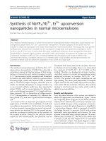
These sheets, larger examples of which can be seen in
Figure 1, were barely detectable when the ampoules
were first removed from the furnace. After some hand-
ling, but before the ampoules were cracked open, these
sheets fell from the interior walls and landed on the
HfTe
2
powder contained within the ampoule. When this
occurred, the mostly rectangular sheets rolled up so that
the side exposed to the powder became the exterior.
Their final curvature was much higher than would be
expected from the 1.1 cm inner diameter of the silica
ampoule.
It is not clear why the addition of Mn enhanced the
formation of HfO
2
. Oxygen impurities in dichalcogen-
ides have been reported in samples grown with manga-
nese due to the manganese oxide whic h can readily
form on powder Mn [12]. These samples also contained
a larger than usual amount of MnTe impurity phase,
thus reducing the overall amount of Te available for
reaction and possibly inducing the Hf to scavenge small
amounts of oxygen from the interior walls of the
ampoules. After the ampoules were opened, the HfTe
2
powders which contained Mn also converted to HfO
2
more quickly, indicating the Mn might act as a catalyst
for the oxidation reaction. This could also explain the
enhanced formation of sheets within ampoules contain-
ing Mn. It is more likely that HfTe
2
, a relatively unstable
compound, would be formed as an intermediate step
before oxidation into HfO
2
during the crystal growth
rather than pure Hf scavenging oxygen its environment.
1 mm
Figure 1 SEM image of a collection of HfO
2
nanosheets mounted
on double sided carbon tape. The sides of each sheet can be
distinguished by their apparent brightness. During growth, the darker
side was attached to the interior wall of the quartz ampoule.
Kidd et al. Nanoscale Research Letters 2011, 6:294
/>Page 2 of 6
The HfO
2
nanosheets were extremely thin considering
their surface area, which ranged up to 25 mm
2
.These
structures could be picked u p with tweezers or other-
wise manipulated for study by SEM, although some
breakage and tearing occurred during handling. While
somewhat brittle in their sensitivity to manipulation, the
sheets were otherwise stable even after being studied for
several months. The sheets showed signs of charging in
the SEM, but not as much as might be expecte d from a
wide gap insulator. As might be expe cted for a charging
sample, edges of the sheet viewed at high magnification
would tend to vibrate and wobble. This effect could be
reduced by lowering the beam current and/or magnifica-
tion. Bright and dark fringe patterns commonly seen on
highly insulating materials like silica were not found,
however. This indicates that the sheets behave more like
semi-conducting materials than true insulators. This
behavior is consistent with the presence of defects in
the crystal lattice that would add carriers or reduce the
band gap as has been seen in other examples of nanos-
tructured HfO
2
[4].
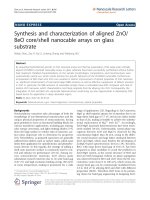
The differences between the two sides of these sheets
can be more readily seen in Figure 2. The side that faced
the interior of the growth ampoule has far more texture
and contains a number of micros copic and sub-micron
scale clusters. The large number of edges associated with
these features makes this side appear brighter in the
SEM. These clusters are well attac hed and likely formed
during the growth process. The side that originally faced
the ampoule walls appears darker in the SEM and is
much smoother. There were far fewer particles attached
to this side, and these particles sometimes seemed to
shift position and their number increased as the samples
were manipulated for various measurements. This indi-
cates the particles on the smooth side appeared to be
material that attached to the sheets after they were
removed from the growth ampoule.
Another interesting feature common to both sides was
the existence of smal l dark circles visible in Figure 2c.
The size and spacing of these features was the same on
both sides, indicating that they are likely pores in the
structure. Measurements taken on the darker side,
which were easier to focus on, showed that these fea-
tures were a ll about 100 nm in dia meter and sur-
rounded by rings that were relatively bright compared
to the rest of the surface. These dark spots were irregu-
larly spaced but very consistent sizes, varying by less
than 20%. While their origin is unclear, t hese features
could arise from defect clusters induced by the high
degree of anisotr opy of the sheets. It is also possible
that they could arise from crystal strain induced by a
chemical reaction transforming hexagonal HfTe
2
into
monoclinic HfO
2
.
The HfO
2
sheets were so thin that, in the SEM, it was
often possible to see through them and measure the
pores of the carbon tape t o which they were attached.
Also, the larger clusters bound to the brighter side were
often detectable as cloudy features (Figure 2c) seen
200 Pm
2 Pm
2 Pm
a
)
b)
c)
Figure 2 SEM images comparing the bright and dark sides of
HfO
2
nanosheets. (a) Wide view image of a curled sheet with a
portion broken off. Bright and dark sides are both visible. (b) Close-
up of the bright side. The surface has a lot of texture and contains
micron scale clusters. Small dark circles can also be seen. (c) Close-
up view of dark side. Surface is much smoother, although some
particulate is attached. Small dark circles are again visible, measuring
about 100 nm in diameter.
Kidd et al. Nanoscale Research Letters 2011, 6:294
/>Page 3 of 6
when the darker side of the sheet faced the electron
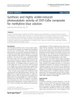
beam. It was possible to directly measure the thickness
of a few of the larger sheets as t hey were bound to the
carbon tape in a perpendicular fashion. The sheet
shown in Figure 3 originally had side lengths that
exceeded 1 mm, and after some fortuitous breakage
became bound to the carbon t ape by its edge. The dif-
ferences between the bright (bottom) and dark (top)
sides are readily apparent in the wide area view shown
in Figure 3a, even though differences in relative intensity
are muted when the sample is viewed at this angle. The
dark side originally facing the quartz is almost feature-
less while the bright side is covered with cluste rs of var-
ious sizes. A higher magnification image of the edge is
shown in Figure 3b. The thickness of the sheet itself,
ignoring particulate or other clusters, was measured to
be about 200 nm. Given that this was one of the thicker
sheets, this implies that t hese HfO
2
nanosheets are
highly two-dimensional structures with dimensions simi-
lar to those used in thin film device applications.
It was apparent that different sheets had different
thicknesses. Measurement of each was very difficult as
mounting the sheets on edge was not a stable configura-
tion and the sheets would often wobble or shift when
high magnification measurements were attempted. How-
ever, o ne qualitative measure of sheet thickness that can
be obtained in the SEM is their degree of transparency.
InoneareaofthesampleshowninFigure4,abundle
composed of either nanotubes or nanorods was found
trapped between two small HfO
2
sheets. This was one of
only a few bundles found in the sample, making it
unclear whether this one-dimensional structure was an
extremely rare growth product or if it was a contaminant
from some bundled TaS
2
nanotubes mounted on a differ-
ent area of the sample stage in the SEM. Regardless of
the bundle’ s origin, the image demonstrates just how
transparent, and therefore thin, these sheets can be. T he
appearance of the bundle as seen through the upper
sheet is smeared out, but not significantly dimmer com-
pared to viewing it directly. This degree of transparency
is similar to that of single-molecule thick materials [9].
The image of Figure 4 was taken using 20 kV elec-
trons which have a mean free path of approximately
10 nm in most materials [13]. The secondary electrons
measured in this image typically have energies less than
50 eV which have mean free paths on the order of
1 nm. To be imaged through the upper sheet, the elec-
tron beam had to pass through the sheet and create sec-
ondary electrons on the surface of the bundle. These
secondary electrons would then need to pass through
the sheet again to reach the detector. This could only
occur if the sheet thickness was not more than a few
nanometers, implying the entire structure w as only
several molecules thick. This represents an extremely
large anisotropy, as this particular sheet was rectangular
with sides measuring roughly 150 μm × 300 μm.
A comparison of the XRD patterns taken from fresh
powder and a relatively large HfO
2
sheet are shown in
Figure 5. The fres h powder was exposed to ai r for only a
few hours while the sheet had been exposed to air for
many days during sample handling and measurements.
Thi s powder and the sheets came from the same growth
a)
b)
10 Pm
1 Pm
Figure 3 SEM images of the edge of a HfO
2
nanosheet. (a) Wide
view showing differences between smooth top side and cluster-
filled bottom side. (b) Close-up of edge. Edge thickness is 200 nm.
5 Pm
Figure 4 SEM images of a bundled nanotube structure
sandwiched between two HfO
2
nanosheets. The bundle can be
easily seen through the transparent upper sheet.
Kidd et al. Nanoscale Research Letters 2011, 6:294
/>Page 4 of 6
ampoule. The pattern from the fresh powder could be
matched to peaks derived from HfTe
2
[14], HfO
2
[15], and
MnTe [16] while the sheet patter n was essentially that of
HfO
2
. The HfO
2
sheet showed some enhancement of the
111
peak at 28.3° but not enough to definitively imply
that the sheet was made up of a single, o riented crystal.
The intensi ty of this peak was also enhanced in the pow-
der sample, but this is likely due to an overlap with a
MnTe peak located at 28.2°. The HfTe
2
peaks showed sig-
nificant (001) orientation from the intensity of the (002)
peak at 13.4°, which should nominally be only 1.5% of the
intensity of the main (011) peak found at 29.3°. This orien-
tation is common for layered dichalcogenides i n powder
form as they are typically made up of small, thin platelets
that are difficult to force into a random configuration.
Another interesting feature of the powder XRD pat-
tern is the appearance of the background in the spe ctra.
It appears as if there are a large number of extremely
broad states that underlie the sharp Bragg peaks in the
spectrum of the powder sample. To better understand
this phenomenon, the powder was left exposed to air
for some time, which resulted in all traces of the HfTe
2
disappearing from the sample. The XRD pattern of t his
aged powder is shown in Figure 6. The only peaks
remaining, aside from the anomalous background, can
be attributed to HfO
2
and the MnTe impurity phase.
The model is actually a simple mixture of a simulated
XRD pattern composed of 5% “macroscopic” and 95%
nanometer scale HfO
2
particles with a mean diameter of
2 nm. In this case, “ macroscopic” means only that the
material is sufficiently large (>50 nm) so that the peaks
are n ot overly broadened as compared to the sharp fea-
tures in the data. The model is quite simple, ignoring all
broadening effects aside from particle size. The features
are essentially too broad for other parameters, such as
strain, to be of much significance. The model does not
include any attempts to actually fit the data by intro du-
cing background effects, orientation, or any other para-
meters. Instead, it is meant to show that the major
features of the data can be well reproduced by assuming
the powder a mixture com posed mainly of randomly
oriented HfO
2
particles with nanometer scale sizes
along with some larger HfO
2
particles. The only features
that are not accounted for in the model are those asso-
ciated with MnTe impurities. The impurities are the
source of sharp peaks near 36.7°, 43.7°, and 48° as well
as the enhancement of the HfO
2
peak near 28.3°. The
successofthismodelsupportstheSEMfindingsthat
the freestanding HfO
2
sheets are extremely anisotropic
materials with nanometer scale thicknesses.
Conclusions
Freestanding two-dimensional nanosheets of HfO
2
and
nanometer scale HfO
2
crystallites were synthesized as
byproducts of the attempted growth of pure and doped
HfTe
2
. The oxide growth was enhanced by the pre sence
XRD
HfO
2
Model
Figure 6 Model and measured XRD pattern for aged powder
sample. The model is composed of a mixture of “ macroscopic”
(>50 nm) and nanometer scale HfO
2
particles. The marked peaks
indicate MnTe impurities not accounted for in the model.
Fresh Powder
HfO
2
Sheet
Figure 5 XRD patterns from fresh powder and a relatively
large HfO
2
nanosheet. Significant peaks related to the different
phases are indicated by symbols.
Kidd et al. Nanoscale Research Letters 2011, 6:294
/>Page 5 of 6
of Mn in the growth ampoule in both cases. It appears
as if the HfO
2
sheets were formed during the growth
process while the nanometer scale crystallites formed
aft er the ampoules were cracked open and the resulting
HfTe
2
powders were exposed to air. While it is not
clear exactly what form the nanometer scale HfO
2
crys-
tallites have, it would not be surprising if they were
two-dimensional as well given that their precursor,
HfTe
2
, is itself a highly two-dimensional layered mate-
rial. Given that it is possible to exfoliate dichalcogenides
to create single molecular layers [8], this synthesis route
could be able to yield two -dimensional nanostructures
in any case.
The HfO
2
sheets were extremely two-dimensional
with thicknesses ranging from a few nanometers to no
more than a few hundred nanometers. In addition to
being extremely th in for their size, they also contained a
large number of defec ts in the form of sub-micron scale
holes. It is not clear what effect these structures have,
but they could relate to other vacancy type defects that
have been shown to influence magnetic behaviors in
nanostructured HfO
2
. These results represent a new
route for synthesizing nanostructured HfO
2
and the first
reported example of freestandin g two-dimensional HfO
2
nanostructures.
Abbreviations
EDS: energy dispersive X-ray spectroscopy; SEM: scanning electron
microscope; XRD: X-ray diffraction.
Acknowledgements
This research was supported by the Battelle foundation and the Iowa Office
of Energy Independence grant #09-IPF-11. The Rigaku X-ray diffractometer
and Bruker EDX systems were purchased by Army Research Office DOD
Grant # W911NF-06-1-0484. Dr. Kidd also acknowledges support from a UNI
Summer Fellowship.
Author details
1
Physics Department, University of Northern Iowa, Cedar Falls, IA 50614, USA
2
Chemistry and Biochemistry Department, University of Northern Iowa, Cedar
Falls, IA 50614, USA
Authors’ contributions
AO and JW performed the microscopy and chemical analysis. KB and LS
carried out the X-ray diffraction measurements and synthesis. TK wrote the
manuscript, directed measurements, and performed analysis of the structural
and chemical properties. All authors read and approved the final manuscript.
Competing interests
The authors declare that they have no competing interests.
Received: 30 October 2010 Accepted: 5 April 2011
Published: 5 April 2011
References
1. John R: High dielectric constant gate oxides for metal oxide Si
transistors. Rep Prog Phys 2006, 69:327.
2. Chau R, Brask J, Datta S, Dewey G, Doczy M, Doyle B, Kavalieros J, Jin B,
Metz M, Majumdar A, Radosavljevic M: Application of high-[kappa] gate
dielectrics and metal gate electrodes to enable silicon and non-silicon
logic nanotechnology. Microelectron Eng 2005, 80:1-6.
3. Tang J, Fabbri J, Robinson RD, Zhu Y, Herman IP, Steigerwald ML, Brus LE:
Solid-solution nanoparticles:use of a nonhydrolytic sol-gel synthesis to
prepare HfO
2
and Hf
x
Zr
1-x
O
2
nanocrystals. Chem Mater 2004,
16:1336-1342.
4. Tirosh E, Markovich G: Control of defects and magnetic properties in
colloidal HfO
2
nanorods. Adv Mater 2007, 19:2608-2612.
5. Qiu X, Howe JY, Cardoso MB, Polat O, Heller W: Size control of highly
ordered HfO
2
nanotube arrays and a possible growth mechanism.
Nanotechnology 2009, 20:455601.
6. Novoselov KS, Geim AK, Morozov SV, Jiang D, Katsnelson MI, Grigorieva IV,
Dubonos SV, Firsov AA: Two-dimensional gas of massless Dirac fermions
in graphene. Nature 2005, 438:197-200.
7. Avouris P, Chen Z, Perebeinos V: Carbon-based electronics. Nature
Nanotechnology 2007, 2:605-615.
8. Joensen P, Frindt RF, Morrison SR: Single-layer MoS
2
. Mater Res Bull 1986,
21:457-461.
9. Novoselov KS, Jiang D, Schedin F, Booth TJ, Khotkevich VV, Morozov SV,
Geim AK: Two-dimensional atomic crystals. Proc Natl Acad Sci USA 2005,
102:10451-10453.
10. Dikin DA, Stankovich S, Zimney EJ, Piner RD, Dommett GHB, Evmenenko G,
Nguyen ST, Ruoff RS: Preparation and characterization of graphene oxide
paper. Nature 2007, 448:457-460.
11. Shi W, Peng H, Wang N, Li CP, Xu L, Lee CS, Kalish R, Lee S-T: Free-
standing single crystal silicon nanoribbons. J Am Chem Soc 2001,
123:11095-11096.
12. Hinode H, Ohtani T, Wakihara M: Homogeneity range and some physical
properties of intercalation compounds of Mn
x
TaS
2
. J Solid State Chem
1995, 114:1-5.
13. Seah MP, Dench WA: Quantitative electron spectroscopy of surfaces: a
standard data base for electron inelastic mean free paths in solids. Surf
Interface Anal 1979, 1:2-11.
14. Smeggil JG, Bartram S: The preparation and X-ray-characterization of
HfTe
2-x
, x = 0.061. J Solid State Chem 1972, 5:391-394.
15. Hann RE, Suitch PR, Pentecost JL: Monoclinic crystal structures of ZrO
2
and HfO
2
Refined from X-ray powder diffraction data. J Am Ceram Soc
1985, 68:C-285-C-286.
16. Wyckoff RWG: Crystal Structures New York: John Wiley & Sons; 1963.
doi:10.1186/1556-276X-6-294
Cite this article as: Kidd et al.: Synthesis of freestanding HfO
2
nanostructures. Nanoscale Research Letters 2011 6:294.
Submit your manuscript to a
journal and benefi t from:
7 Convenient online submission
7 Rigorous peer review
7 Immediate publication on acceptance
7 Open access: articles freely available online
7 High visibility within the fi eld
7 Retaining the copyright to your article
Submit your next manuscript at 7 springeropen.com
Kidd et al. Nanoscale Research Letters 2011, 6:294
/>Page 6 of 6