Báo cáo hóa học: " Growth of carbon nanowalls at atmospheric pressure for one-step gas sensor fabrication" ppt
Bạn đang xem bản rút gọn của tài liệu. Xem và tải ngay bản đầy đủ của tài liệu tại đây (1.01 MB, 9 trang )
NANO EXPRESS Open Access
Growth of carbon nanowalls at atmospheric
pressure for one-step gas sensor fabrication
Kehan Yu
1
, Zheng Bo
1
, Ganhua Lu
1
, Shun Mao
1
, Shumao Cui
1
, Yanwu Zhu
2
, Xinqi Chen
3
, Rodney S Ruoff
2
,
Junhong Chen
1*
Abstract
Carbon nanowalls (CNWs), two-dimensional “graphitic” platelets that are typically oriented vertically on a substrate,
can exhibit similar properties as graphene. Growth of CNWs reported to date was exclusively carried out at a low
pressure. Here, we report on the synthesis of CNWs at atmosphere pressure using “direct current plasma-enhanced
chemical vapor deposition” by taking advantage of the high electric field generated in a pin-plate dc glow
discharge. CNWs were grown on silicon, stainless steel, and copper substrates without deliberate introduction of
catalysts. The as-grown CNW material was mainly mono- and few-layer graphene having patches of O-containing
functional groups. However, Raman and X-ray photoelectron spectroscopies confirmed that most of the oxygen
groups could be removed by thermal annealing. A gas-sensing device based on such CNWs was fabricated on
metal electrodes through direct growth. The sensor responded to relatively low concentrations of NO
2
(g) and NH
3
(g), thus suggesting high-quality CNWs that are useful for room temperature gas sensors.
PACS: Graphene (81.05.ue), Chemical vapor deposition (81.15.Gh), Gas sensors (07.07.Df), Atmospheric pressure
(92.60.hv)
Introduction
Graphene possesses many extraordinary properties and
has been the subject of intense scientific interest [1-12].
Exceptional values have been reported of: ballistic elec-
tron mobi lity (>200,000 cm
2
/V- s for particular samples)
[13,14], high thermal conductivity (5,000 W/m-K) [15],
Young’ s modulus (approximately 1,1 00 GPa), fracture
strength (125 GPa) [16], and a high specific surface area
(approximately 2,600 m
2
/g) relevant to electrical energy
storage [5].
“Carbon nanowalls” (CNWs), also referred to as “car-
bon nanoflakes” , are two-dimensional “graph itic ” plate-
lets that are typically oriented vertical ly on a substrate.
An individual CNW has been reported to have a few
stacked layers ("graphitic”) with typical lateral dimen-
sions of several micrometers [17]. CNWs might exhibit
similar properties as graphene. The sharp edges and ver-
tical orientation make CNWs a potential field emission
material [18-20]. The high surface area of CNWs could
be ideal for catalyst support. R ecently, CNWs have been
tested for use in Li-ion batt eries [21] and electrochemi -
cal capacitors [22]. CNWs can also be used as a tem-
plate for loading other nanomaterials; and the resulting
hybrid nanostructures are potentially useful for various
applications [23-25].
CNWs were discovered by Wu et al. [26] and since then
they have been grown using various low-pressure pro-
cesses. Initially, substrates were sputter-coated with transi-
tion metals as catalysts and the growth of CNWs was
typically carried out in a microwave plasma-enhanced che-
mical vapor deposition ( MPECVD) system [23]. Only a
few studies of CNW growth using low-pressure, low-vol-
tage, high -current dc PECVD have been conducted [27] .
The growth parameters were very similar to those used for
PECVD growth of carbon nanotubes (CNTs), but the
pressure used in the reactor chamber was much lower (≤1
Torr) [17,26-31]. There have been a number of studies
focused on understanding the CNW growth mechanism
and thus targeting control of the growth process
[22,26,32,33]. Nevertheless, to our knowledge, no CNW
growth has been reported at atmospheric pressure.
Here, we report on the synthesis of CNWs using dc
PECVDatatmosphericpressurebytakingadvantageof
the high electric field generated in a pin-plate d c glow
* Correspondence:
1
Department of Mechanical Engineering, University of Wisconsin-Milwaukee,
Milwaukee, WI 53211, USA.
Full list of author information is available at the end of the article
Yu et al. Nanoscale Research Letters 2011, 6:202
/>© 2011 Yu et al; licensee Springer. This is an Open Access article distributed under the terms of the Creative Commons Attribution
License (http:/ /creativecommons.org/licenses/by/2.0), which permits unrestricted use, distribution, and reproduction in any medium,
provided the origina l work is properly cited.
discharge. In general, PECVD processes for the material
growth can occur at a relatively lower temperature due
to the significant contribution from energetic electrons
to cracking down precursor species. Prior studies using
low-pressure PECVD systems to grow CNWs m ainly
rely on the increased mean free path (mfp) of electrons
in vacuum to obtain energetic electrons needed for the
decomposition of carbon precursors. The electric field
generated in the low-pressure PECVD system is gener-
ally low. By using a pair of asymmetric discharge elec-
trodes, i.e., a sharpened tungsten tip as cathode and a
planar substrate as anode, a highly enhanced electric
field about two to three orders of magnitude higher
than that in the previous MPECVD system is generated
near the tungsten tip so that the mfp of electrons can
be lowered or the system pressure can be elevated (e.g.,
to atmospheric pressure) to generate similar energetic
electrons.
Our method does not require a sealed reactor, which
presents a path for continuous line production of CNWs.
An atmospheric-pressure process to replace the vacuum
process should also reduce the product cost. A recent
study on the high cost of modern vacuum deposition
methods highlighted the need for atmospheric synthesis
[34]. The as-grown CNWs were decorated with oxygen-
containing functional groups. By thermal annealing in H
2
,
most oxygen functional groups can be effectively elimi-
nated. In addition, most of the product CNWs are non-
aggregated with large surface area, which makes the
product readily useful for various applications such as sen-
sing and catalysis. This is in contrast to stacked CNWs
that require additional dispersion, such as through ultraso-
nication, to obtain individual CNWs. To illustrate the
advantage of our growth method, CNWs de liberately
grown between metal electrodes were used for d etection of
low-concentration gases including NO
2
and NH
3
, thereby
demonstrating a one-step gas sensor fabrication process.
Experimental details
The plasma reactor consists of a quartz tube that houses
a tungsten needle cathode, a grounded graphite rod
anode, and a dc high negative voltage supply (EMCO
4100N; up to -1 0 kV) to drive the dc glow discharge.
Argon was used as the plasma gas. A tube furnace
(TF55035 A-1, Lindberg/BLUE M, Asheville, USA) was
used to heat the reactor. Silicon wafers, stainless steel
plates, and Cu plates were used as substrates. The sub-
strates were mounted on the top of the graphite rod; no
metals were added as potential catalysts.
Prior to the growth, the substrate was brought to 700°C
and held at that temperature for 10 min in an Ar/H
2
flow
(1% H
2
by volume) of 500 standard cubic centimeters per
minute (sccm). The two discharge electrodes were sepa-
ratedbyadistanceof1.0cm.ThentheAr/H
2
flow was
switched to an Ar/ethanol flow (1,000 sccm) through an
ethanol bubbler. The dc glow discharge was ignited at a
dc voltage of 3.3 kV. Once the dc plasma was formed, the
voltage between the electrodes immediately dropped to
2.2 kV, and the current was about 1.3 mA, yielding a
total plasma power of 2.9 W.
The plasma was typically left on for 15 min. Then, the
plasma was turned off and the system was cooled down to
room temperature with a flow of Ar/H
2
only. Throughout
the process, the reactor pressure was maintained at one
atmosphere. The reactor temperature was measured as
close to 700°C (the preset furnace temperature) using a
thermocouple. This suggests that the energy dissipated in
thedcglowdischargewasnon-thermal (electrons were
preferentially heated by the plasma) and heavy species
(e.g., gas molecules, atoms, radicals, a nd ions) were not
substantially heated by the plasma. After the plasma was
turned off, a layer of black, powder-like material could be
seen on the substrate. In order to reduce oxygen func-
tional groups decorated on the as-grown CNWs, the
CNWs were thermally annealed at 900°C in H
2
flow
(1,000 sccm) for 2 h at atmospheric pressure.
Scanning electron microscopy (SEM) analysis of the as-
grown samples was performed with a Hitachi S-4800 SEM
having a stated resolution of 1.4 nm at 1 kV acceleration
voltage. Transmission electron microscopy (TEM) was
performed with a Hitachi H 9000 NAR TEM, which has a
stated point resolution of 0.18 nm at 300 kV in the phase
contrast, high-resolution TEM (HRTEM) imaging mode.
In order to perform TEM characterizations, the as-grown
CNWs were wetted with ethanol and contact-transferred
to lacey carbon-coated TEM grids or bare Cu grids. A
confocal Raman s ystem, which is composed of a TRIAX
320 spectrograph, liquid nitrogen-cooled CCD (CCD
3000), and “spectrum one” CCD controller (all manufac-
tured by HORIBA Jobin Yvon), was used to record the
Raman spectra of the samples with an excitation wave-
length of 532 nm. X-ray photoelectron spectroscopy (XPS,
Omicron NanoESCA probe, Omicron NanoTechnology
GmbH, Taunusstein, Germany) was used to analyze the
chemical composition as well as the nature of the chemical
bonds in the as-grown CNWs.
Gold-interdigitated electrodes with both finger width
and inter-finger spacing of about 1 μm and thickness of
50 nm were fabricated using an e-beam lithography pro-
cess (R aith 150 lithography tool, 30 kV) on an Si wafer
with a top layer of thermally-formed SiO
2
(thickness of
200 nm). Sensor current was meas ured using a Keithley
2602 source meter.
Results and discussion
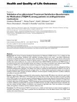
Figure 1 shows a schematic of the atmospheric dc
PECV D system for the CN W synthesis without any cat-
alysts. The morphology of the as-grown CNWs is
Yu et al. Nanoscale Research Letters 2011, 6:202
/>Page 2 of 9
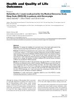
displayed in t he SEM images shown in Figure 2. The
CNWs were uniformly distributed on the Si substrate
(Figure 2a,2b). The total area on the substrate that was
covered w ith CNWs depended on the discharge power
and the distance between the electrodes. In our experi-
ments, the area covered with CNWs could be up to
approximately 1 cm
2
. The dimensions of individual
CNWs ranged from about 200 × 200 nm
2
(Figure 2e) to
1×1μm
2
(Figure 2c), which can be controlled by the
growth time. The thickness of the CNWs was typically
below 10 nm, (top-view of CNWs, Figure 2c,2e; side-
view of CNWs, Figure 2d). Small pinholes were
observed in the CNWs ( Figure 2e). Wu et al. used a dc
bias of -185 V to promote growth and vertical alignment
[26]. Hiramatsu et al. stated that the reactant type influ-
ences the CNW morphology [30], in the case of C
2
F
6
/
H
2
, they synthesized vertically aligned C NWs using a
radio-frequency plasma. In our experiments, most of the
CNWs were randomly orie nted but pointing away from
the substrate surface, although a dc bias of 2.2 kV was
applied between the electrodes throughout the growth
process. In some areas, CNW clusters were found
(Figure 2f) sparsely distributed on the substrate. Each
CNW cluster had a “flower-like” sh ape with CNWs pro-
jecting in all direct ions, which is similar to the observa-
tions made by Chuang et al [35]. Similar structures were
also found for CNWs grown on a Cu substrate (see Fig-
ure S-1 in Additional file 1).
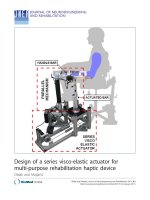
Raman spectra showed D and G bands located at
1,347 and 1,584 cm
-1
, respe ctively (Figure 3a). The bulk
grap hite has a G peak at approximately 1,580 cm
-1
[36],
whereas a D peak at approximately 1,350 cm
-1
is seen
for defective graphit e [37]. The position and shape of
the G peak suggest that graphitized carbon was synthe-
sized. The 2 D band (2,682 cm
-1
) suggests the presence
of “ graphene-like” materials. A very small 2D’ band
(approximately 3,233 cm
-1
) indicates the existence of the
D’ band that is however probably convoluted with the G
band. The G peak for graphene sheets [38,39] occurs at
approximately 1,580 cm
-1
, and this peak broadens and
significantly shifts to 1,594 cm
-1
for graphite oxide
sheets [40,41]. The upshift of what we attribute as the G
peak (to 1,584 cm
-1
) suggests a possibility of a high frac-
tion of oxygen contained in the as-grown CNWs. In the
growth of CNTs, it was stated that oxygen etches the
carbon on the catalyst particle surface and thus pro-
motes CNT growth [42]. We found that oxygen-con-
taining radicals also appear to be essential for the
growth of CNWs in our growth attempts. Hung et al.
attributed the formation of nucleation sites for the
growth of CNWs to the etching by oxygen-containing
species [22]. In addition to using ethanol, we tried to
synthesize CNWs with pure CH
4
or with n-hexane
vapor with Ar as the carrier gas, but no CNWs were
observed. However, CNWs could be readily synthesized
with CH
4
and water vapor (again with Ar as the carrier
gas), where the presence of C-OH groups was confirmed
with optical emission spectroscopy(seeFigureS-2and
S-3 in Additional file 1). The 1:2 O/C ratio in the etha-
nol precursor is perhaps too high to produce high-purity
“ graphene-like” material with the approach we have
used, but we note the recent report of very carbon-pure
graphene made from ethanol usi ng a microwave plasma
operated at low pressure [43]. It is likely that the oxygen
radicals etch away carbon as it is deposited during the
growth, which may explain broken edges and pinholes
on the resulting CNW sheets.
The 2 D peak is a signatur e of graphitic carbon in the
graphene-like materials [11]. The Raman spectrum
obtained from the as-grown CNWs exhibits a pea k cen-
tered at 2,682 cm
-1
(Figure 3a, pink curve), indicating
that the analyzed region consists of considerable amount
of graphene or oxygenated graphene. After thermal
annealing, the 2 D peak shifted to 2,675 cm
-1
(Figure 3a,
olive curve). This trend is in agreement with literature.
The 2 D peaks were reported at 2,861 cm
-1
for mono-
layer graphene oxide [44], and 2,700 cm
-1
for monolayer
graphene [45]. For monolayer r educed graphene oxide,
the 2 D peak was found around 2,700 cm
-1
or below
2,700 cm
-1
[44,46, 47]. The 2 D band is very sensitive to
Figure 1 Experimental setup for atmospheric pressure dc PECVD growth of CNWs.
Yu et al. Nanoscale Research Letters 2011, 6:202
/>Page 3 of 9
the number of layers in the sample. Figure 3a shows sin-
gle Lorentzian pro files of the few-layered graphene
sheets, which are different from the case of few-layered
graphene sheets generated by micromechanical cleavage
of graphite [11]. The reason is that an ordered stacking
(i.e., ABAB stacking) and therefore an e lectronic cou-
pling do not occur in all region of a CNW sheet [48].
The D peak and 2D’ peak are attributed to the struc-
tural disorder in the CNW sheets [38]. The intensit y of
the D band is at least partly a consequence of the high
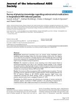
Figure 2 Morphology of the as-grown CNWs displayed in the SEM images. (a) An SEM image of CNWs on a silicon substrate; primary
beam incident kinetic energy was 30 keV. (b) CNWs uniformly distributed on the substrate over approximately 1 cm
2
. (c-e) The CNWs were
quasi-transparent to the SEM electron beam. (f) The cluster of CNWs is “flower-like”.
Yu et al. Nanoscale Research Letters 2011, 6:202
/>Page 4 of 9
fraction of open edges and pinholes within the CNWs
(Figure 2a) [49]. The disorder-induced combination
mode(D+G)atabout2,920cm
-1
was also observed.
For comparison of the relative intensity of each peak,
the Raman spectra were n ormalized. Both of the G
peaks intensities before and after reduction were fixed
at 1 (Figure 3a). The band area ratios I(2D)/I(G)
increased from 0.79 to 0.81 after thermal reduction.
This change indicates a s light increase of s p
2
carbon
domain. The band area ratios I(D)/I(G) decreased from
1.73 to 1.63 after thermal reduction. The reducing I(D)/
I(G) indicates a decreasing degree of disordered carbon.
The ratio of the intensity of the G band to that of the D
band I(G)/I(D) is directly related to the in-plane crystal-
lite size L
a
(nanometers) = 19.2 (I(G)/I(D)), and an
increase of L
a
from 11.1 to 11.8 nm was obtained [50].
XPS studies reveal the nature of the carbon and oxy-
gen bonds present in the samples (Figure 3b,3c). The
XPS peaks were decomposed with a Gaussian fit. Analy-
sis of the CNWs shows a significant reduction of oxygen
functional groups after thermal annealing in H
2
for 2 h
at 900°C. B riefly, the as-grown CNWs contained non-
oxygenated ring C (71.1%), sp
3
C hybridized to C (C-C,
18.5%), C in C-OH bonds (9.1%), the carboxylate carbon
(O = C-OH, 1.1%), and carbonyl carbon (<0.2%). After
thermal annealing, only a small fraction of C in C-OH
(1.7%) remained in the CNWs. C in C = C and C-C
bonds increased to 72.8% and 25.5%, respectively. The
O1 s spectra showed similar reduction of O - the peak
weakened after reduction in H
2
(Figure 3c). Howev er,
the accurate determination of every O-containing group
after the thermal reduction is quite challenging due to
1000 1500 2500 3000 3500
2D'
3218
2D'
3233
D
1347
D
1343
D+G
~2920
Normalized
Intensity
Wavenumber (cm
-1
)
Original
Reduced
2D
2675
2D
2682
G
1584
G
1577
D+G
~2920
294 292 290 288 286 284 282 280
CNW
O=C-OH
C-OH
C-C
Binding Energy (eV)
C=C
H
2
900
o
C
C-OH
C-C
C
=
C
538 536 534 532 530 528
C=O
Bindin
g
Ener
gy
(
eV
)
C-OH
C-OH
H
2
900
o
C
CNW
b
c
a
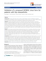
Figure 3 Raman and XPS spectra. (a) Raman spectrum of CNWs (original and reduced) showing the presence of D and G bands as well as the
overtone and combination mode features taken with 532 nm laser excitation. (b) The C1 s and (c) the O1 s XPS spectra of CNWs before and
after thermal annealing. The as-grown CNWs contained many oxygen functional groups, while only a low fraction of hydroxyl groups remained
after thermal reduction in H
2
for 2 h at 900°C. The peak components (green curves) were analyzed with a Gaussian fit.
Yu et al. Nanoscale Research Letters 2011, 6:202
/>Page 5 of 9
the insufficient signal-to-noise ratio. Positions of carbon-
related and oxygen-related peaks in the XPS spectra are
consistent with those of oxidized graphene reported
recently [51]. The reduction of oxygen functional groups
suggested by the XPS spectra is consistent with the
Raman data.
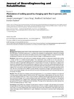
TEM images of the product CNWs were shown in
Figure 4. Two low-magnification TEM images are
shownasFigure4aand4b.TheinsetinFigure4aisa
SAD pattern of the CNW sample, which displays a
hexagonal pattern confirming the threefold symmetry of
the arrangement of carbon atoms. Well-defined diffrac-
tion spots (instead of ring patter ns) were ob served for
most CNWs, while ring patterns were observed sel-
domly, indicating the mostly few-layer structure and a
high degree of crystallinity of the resulting CNWs.
HRTEM examination of the samples conf irms that the
CNW sheets consist of only a few graphene layers (typi-
cally one to five layers, Figure 4c,4d). The edges of
the suspended CNWs often fold back, allowing for a
Figure 4 TEM characterization of CNWs. (a) A CNW sheet supported on a Cu grid. Electron diffraction from the CNW is shown as an inset. (b)
The areas of a CNW with different thicknesses and wrinkles. (c) and (d) HRTEM images showing the edges of CNW film consisting of one, and
five graphene layers, respectively. (d corresponds to the area defined by the white box in b). (e) HRTEM iamge of a CNW sheet with two well-
crytallined regions (arrowed). The diffractogram (the inset) is from the red-squared region in (e). (f) A filtered image of the squared region in (e).
(g) The intensity profile along the red dashed line in (f).
Yu et al. Nanoscale Research Letters 2011, 6:202
/>Page 6 of 9
cross-sectional view of the graphene [48,52]. By obser-
ving these edges through HRTEM images, the number
of layers at multiple locations on the graphene can be
measured (Figure 4c,4d). The estimated interlayer spa-
cing is about 3.50 Å, which is a little larger than the d-
spacing of graphite (3.36 Å). The small amount of oxy-
gen-containing functional groups might be the main
reason for this difference [44].
Although a fraction of surface area of the CNW may be
covered with oxygen groups, there are well-crystallined
graphitic regions (sp
2
carbon)intheCNW.Figure4eis
an HRTEM image from another CNW sample and shows
two regions (arrowed) with well-d efined fringes implying
the good crystallinity of the CNW. The diffractogram
(the inset in Figure 4e) of the red-squared region in
Figure 4e gives a set of hexagonal spots, suggesting the
possible monolayer nature of the region. We further
inspected the squared area in Figure 4e by performing
Fourier filtering. A filtered image with atomic resolutio n
is shown in Figure 4f. The “ honeycomb-like” carbon
rings in Figure 4f clearly illustrate that the CNW consists
of monolayer graphene. The length of the C-C bond in
graphene is 0.142 nm [53], resulting in a hexago n with a
width of 0.25 nm. We analyzed the intensity profile
(Figure 4g) along the red dashed line in Figure 4e. The
hexagon width measured from the intensity outline in
Figure 4g is about 0.246 nm, which is in good agreem ent
with the expected value of 0.25 nm. Our HRTEM analysis
indicates the existence of monolayer graphene in the pro-
duct CNWs.
To demonstrate the gas sensing performance o f the
as-grown CNWs, CNWs were gro wn on in terdigitat ed
Au electrodes. The interdigitated electrodes with f inger
width and inter-finger spacing both of 1 μm were fabri-
cated by an e-beam lithography process and used as the
sensor substrates [54]. The growth duration was 5 min
as it was found that this exposure would yield a CNW
film with CNWs connecting with the two neighbouring
electrodes (Figure 5a). The sensor operated at room
temperature and was periodically exposed to clean dry
air flow of 2 lpm for 10 min to record a base value of
the sensor conductance, NO
2
(100 ppm) or NH
3
(1%)
dilutedinairof2lpmfor15mintoregisterasensing
signal, and then a lab air flow of 2 lpm again for 25 min
to recover the device. A constant dc bias (= 0.1 V) was
applied across the two gold terminals.
Upon the introductio n of NO
2
, the sensor current
went up, i.e., the conductance of the sensor increased
(Figure 5b, red curve). Upon exposure to NH
3
,thesen-
sor current went down, i.e., the conductance of the sen-
sor decreased (Figure 5b, blue curve). Thus, the CNW
film behaves like a p-type semiconductor, similar to gra-
phene exposed to air. NO
2
is a strong oxidizer with
electron-withdrawi ng power [55]; therefore, electron
transfer from the CNWs to adsorbed NO
2
leads to
increased hole concentration and enhanced electrical
conduction in the C NW network. Likewise, the
absorbed NH
3
molecules donate electrons to CNW and
neutralize holes partially in the CNW, which results in a
lower sensor current in the device. The sensing behavior
of the as-grown CNW is consistent with a typical gra-
phene or reduced graphene oxide gas sensor [54].
Conclusions
In summary, we have demonstrated a new path to low-
cost production of CNWs on Si, stainless steel, and Cu
(a)
0 25 50 75 100 125 150
0.10
0.12
0.14
0.54
0.56
NO
2
(100 ppm)
NH
3
(1 %)
Current (
P
A)
Time (min)
Gas
Air
GasAir
GasAir
Air
(
b
)
Figure 5 Gas sensing performance of as-produced CNWs. (a)
SEM image of CNWs bridging two neighboring Au fingers of an
interdigitated electrode. Gases are detected by measuring the
change in the device current while applying a constant dc bias to
the device. (b) Room-temperature sensing response for NO
2
and
NH
3
.
Yu et al. Nanoscale Research Letters 2011, 6:202
/>Page 7 of 9
substrates with a dc PECVD system operated at atmo-
spheric pressure. SEM, HRTEM, Raman spectroscopy,
and XPS reveal that the as-grown CNW material has a
significant fraction of chemically functionalized mono-
and few-layer graphene, with patches of O-con taining
functional groups; however, most of the O-conta ining
functional groups can be removed by thermal annealing.
Our atmospheric pressure process can be readily scaled
up for large area growth through the use of an array of
tungsten needle cathodes. A gas sensing device based on
as-produced CNW film responds to low-concentration
NO
2
or NH
3
in a similar fashion as sensing device s
based on graphene or reduced graphene oxide. There-
fore, a simple one-step gas sensor fabrication process
has been demonstrated.
Additional material
Additional file 1: CNWs grown on a Cu plate and stainless steel
plates; emission spectrum of dc glow discharge. Figure S-1 SEM
images of CNWs grown on a Cu plate with different surface density.
Figure S-2 (a) SEM image showing no presence of CNWs on a stainless
steel plate when CH
4
alone is used as the precursor gas. (b) CNWs
grown using CH
4
and H
2
O. The growth time for both cases is 5 min.
Figure S-3 Emission spectrum of glow discharge obtained by subtracting
the background signal (without discharge) from the total spectrum (with
discharge). Emission lines of OH are remarkable in the spectrum of a
CNW sample.
Acknowledgements
This work was supported by the US NSF (CMMI-0900509), the US DOE (DE-
EE0003208), and We Energies. The authors thank H. A. Owen for technical
support with SEM and R. Arora for technical support with Raman, M.
Gajdardziska-Josifovska for providing TEM access, D. Robertson for technical
support with TEM, and L. E. Ocola for assistance in the electrode fabrication.
The SEM imaging was conducted at the EML of UWM. The TEM
characterization was carried out at the UWM HRTEM Laboratory. The e-beam
lithography was performed at the Center for Nanoscale Materials of Argonne
National Laboratory, which is supported by the US Department of Energy
(DE-AC02-06CH11357).
Author details
1
Department of Mechanical Engineering, University of Wisconsin-Milwaukee,
Milwaukee, WI 53211, USA.
2
Department of Mechanical Engineering and the
Texas Materials Institute, University of Texas at Austin, Austin, TX 78712, USA.
3
Keck-II Center, Northwestern University, Evanston, IL 60208, USA
Authors’ contributions
KHY carried out the CNW synthesis, SEM characterization, growing CNWs
into a gas sensor, and drafted the manuscript. ZB provided the basic idea of
the dc-plasma reactor design. GHL carried out the TEM and HRTEM
characterization, fabricated the sensor electrode, carried out the gas sensing
experiments, and helped to draft the manuscript. SM helped to carry out
the Raman analysis. SMC carried out the XRD analysis. YWZ participated in
the HRTEM characterization. XQC carried out the XPS characterization. RSR
and JHC helped draft the manuscript and finalized the version to be
published. All authors read and approved the final manuscript.
Competing interests
The authors declare that they have no competing interests.
Received: 16 November 2010 Accepted: 9 March 2011
Published: 9 March 2011
References
1. Li X, Cai W, An J, Kim S, Nah J, Yang D, Piner R, Velamakanni A, Jung I,
Tutuc E, Banerjee SK, Colombo L, Ruoff RS: Large-area synthesis of high-
quality and uniform graphene films on copper foils. Science 2009,
324:1312-1314.
2. Berger C, Song Z, Li X, Wu X, Brown N, Naud C, Mayou D, Li T, Hass J,
Marchenkov AN, Conrad EH, First PN, de Heer WA: Electronic confinement
and coherence in patterned epitaxial graphene. Science 2006,
312:1191-1196.
3. Li X, Zhu Y, Cai W, Borysiak M, Han B, Chen D, Piner RD, Colombo L,
Ruoff RS: Transfer of large-area graphene films for high-performance
transparent conductive electrodes. Nano Lett 2009, 9:4359-4363.
4. Cai W, Zhu Y, Li X, Piner RD, Ruoff RS: Large area few-layer graphene/
graphite films as transparent thin conducting electrodes. Appl Phys Lett
2009, 95:123115.
5. Stoller MD, Park S, Zhu Y, An J, Ruoff RS: Graphene-based ultracapacitors.
Nano Lett 2008, 8:3498-3502.
6. Novoselov KS, Geim AK, Morozov SV, Jiang D, Katsnelson MI, Grigorieva IV,
Dubonos SV, Firsov AA: Two-dimensional gas of massless Dirac fermions
in graphene. Nature 2005, 438:197-200.
7. Novoselov KS, Jiang D, Schedin F, Booth TJ, Khotkevich VV, Morozov SV,
Geim AK: Two-dimensional atomic crystals. Proc Natl Acad Sci USA 2005,
102:10451-10453.
8. Novoselov KS, Geim AK, Morozov SV, Jiang D, Zhang Y, Dubonos SV,
Grigorieva IV, Firsov AA: Electric field effect in atomically thin carbon
films. Science 2004, 306:666-669.
9. Meyer JC, Geim AK, Katsnelson MI, Novoselov KS, Booth TJ, Roth S: The
structure of suspended graphene sheets. Nature 2007, 446:60-63.
10. Novoselov KS, McCann E, Morozov SV, Fal’ko VI, Katsnelson MI, Zeitler U,
Jiang D, Schedin F, Geim AK: Unconventional quantum Hall effect and
Berry’s phase of 2 pi in bilayer graphene. Nature Phys 2006, 2:177-180.
11. Ferrari AC, Meyer JC, Scardaci V, Casiraghi C, Lazzeri M, Mauri F, Piscanec S,
Jiang D, Novoselov KS, Roth S, Geim AK: Raman spectrum of graphene
and graphene layers. Phys Rev Lett 2006, 97:187401.
12. Stankovich S, Dikin DA, Dommett GHB, Kohlhaas KM, Zimney EJ, Stach EA,
Piner RD, Nguyen ST, Ruoff RS: Graphene-based composite materials.
Nature 2006, 442:282-286.
13. Chen J-H, Jang C, Xiao S, Ishigami M, Fuhrer MS: Intrinsic and extrinsic
performance limits of graphene devices on SiO
2
. Nature Nanotech 2008,
3:206-209.
14. Bolotin KI, Sikes KJ, Jiang Z, Klima M, Fudenberg G, Hone J, Kim P,
Stormer HL: Ultrahigh electron mobility in suspended graphene. Solid
State Commun 2008, 146:351-355.
15. Balandin AA, Ghosh S, Bao W, Calizo I, Teweldebrhan D, Miao F, Lau CN:
Superior thermal conductivity of single-layer graphene. Nano Lett 2008,
8:902-907.
16. Lee C, Wei X, Kysar JW, Hone J: Measurement of the elastic properties
and intrinsic strength of monolayer graphene. Science 2008, 321:385-388.
17. Malesevic A, Kemps R, Vanhulsel A, Chowdhury MP, Volodin A, van
Haesendonck C: Field emission from vertically aligned few-layer
graphene. J Appl Phys 2008, 104:084301.
18. Watcharotone S, Ruoff RS, Read FH: Possibilities for graphene for field
emission: modeling studies using the BEM. Physics Procedia 2008, 1:71-75.
19. Hiraki H, Jiang N, Wang HX, Hiraki A: Electron emission from nano-
structured carbon composite materials - an important role of the
interface for enhancing the emission. J Phys IV 2006, 132:111-115.
20. Takyo G, Kono S, Goto T, Sasaoka H, Nishimura K: Origin of field emission
from a nano-diamond/carbon nanowall electron emitter. Jpn J Appl Phys
2008, 47:2241-2243.
21. Tanaike O, Kitada N, Yoshimura H, Hatori H, Kojima K, Tachibana M: Lithium
insertion behavior of carbon nanowalls by dc plasma CVD and its heat-
treatment effect. Solid State Ion 2009, 180:381-385.
22. Hung TC, Chen CF, Whang WT: Deposition of carbon nanowall flowers on
two-dimensional sheet for electrochemical capacitor application.
Electrochem Solid State Lett 2009, 12:K41-K44.
23. Wu YH, Yang BJ, Han GC, Zong BY, Ni HQ, Luo P, Chong TC, Low TS,
Shen ZX: Fabrication of a class of nanostructured materials using carbon
nanowalls as the templates. Adv Funct Mater 2002, 12:489-494.
24. Yang BJ, Wu YH, Zong BY, Shen ZX: Electrochemical synthesis and
characterization of magnetic nanoparticles on carbon nanowall
templates. Nano Lett 2002, 2:751-754.
Yu et al. Nanoscale Research Letters 2011, 6:202
/>Page 8 of 9
25. Wang H, Quan X, Yu HT, Chen S: Fabrication of a TiO
2
/carbon nanowall
heterojunction and its photocatalytic ability. Carbon 2008, 46:1126-1132.
26. Wu YH, Qiao PW, Chong TC, Shen ZX: Carbon nanowalls grown by
microwave plasma enhanced chemical vapor deposition. Adv Mater 2002,
14:64-67.
27. Kobayashi K, Tanimura M, Nakai H, Yoshimura A, Yoshimura H, Kojima K,
Tachibana M: Nanographite domains in carbon nanowalls. J Appl Phys
2007, 101:094306.
28. Shang NG, Papakonstantinou P, McMullan M, Chu M, Stamboulis A,
Potenza A, Dhesi SS, Marchetto H: Catalyst-free efficient growth,
orientation and biosensing properties of multilayer graphene nanoflake
films with sharp edge planes. Adv Funct Mater 2008, 18:3506-3514.
29. Wakana T, Masato U, Mineo H, Yutaka T, Hiroyuki K, Masaru H: Electrical
conduction control of carbon nanowalls. Appl Phys Lett 2008, 92:213103.
30. Hiramatsu M, Shiji K, Amano H, Hori M: Fabrication of vertically aligned
carbon nanowalls using capacitively coupled plasma-enhanced chemical
vapor deposition assisted by hydrogen radical injection. Appl Phys Lett
2004, 84:4708-4710.
31. Kondo S, Hori M, Yamakawa K, Den S, Kano H, Hiramatsu M: Highly reliable
growth process of carbon nanowalls using radical injection plasma-
enhanced chemical vapor deposition. J Vac Sci Technol, B 2008,
26:1294-1300.
32. Shimabukuro S, Hatakeyama Y, Takeuchi M, Itoh T, Nonomura S: Effect of
hydrogen dilution in preparation of carbon nanowall by hot-wire CVD.
Thin Solid Films 2008, 516:710-713.
33. Levchenko I, Ostrikov K, Rider AE, Tam E, Vladimirov SV, Xu S: Growth
kinetics of carbon nanowall-like structures in low-temperature plasmas.
Phys Plasmas 2007, 14:063502.
34. Gutowski TG, Branham MS, Dahmus JB, Jones AJ, Thiriez A, Sekulic DP:
Thermodynamic analysis of resources used in manufacturing processes.
Environ Sci Technol 2009, 43:1584-1590.
35. Chuang ATH, Boskovic BO, Robertson J: Freestanding carbon nanowalls by
microwave plasma-enhanced chemical vapour deposition. Diamond Relat
Mater 2006, 15:1103-1106.
36. Vidano RP, Fischbach DB, Willis LJ, Loehr TM: Observation of Raman band
shifting with excitation wavelength for carbons and graphites. Solid State
Commun 1981, 39:341-344.
37. Tuinstra F, Koenig JL: Raman spectrum of graphite. J Chem Phys 1970,
53:1126-1130.
38. Ferrari AC: Raman spectroscopy of graphene and graphite: Disorder,
electron-phonon coupling, doping and nonadiabatic effects. Solid State
Commun 2007, 143:47-57.
39. Casiraghi C, Pisana S, Novoselov KS, Geim AK, Ferrari AC: Raman fingerprint
of charged impurities in graphene. Appl Phys Lett 2007, 91:233108.
40. Stankovich S, Dikin DA, Piner RD, Kohlhaas KA, Kleinhammes A, Jia Y, Wu Y,
Nguyen ST, Ruoff RS: Synthesis of graphene-based nanosheets via
chemical reduction of exfoliated graphite oxide. Carbon 2007,
45:1558-1565.
41. Dong X, Huang W, Chen P: In situ synthesis of reduced graphene oxide
and gold nanocomposites for nanoelectronics and biosensing. Nanoscale
Res Lett 2010, 6:60-65.
42. Futaba DN, Goto J, Yasuda S, Yamada T, Yumura M, Hata K: General rules
governing the highly efficient growth of carbon nanotubes. Adv Mater
2009, 21:4811-4815.
43. Dato A, Radmilovic V, Lee Z, Phillips J, Frenklach M: Substrate-free gas-
phase synthesis of graphene sheets. Nano Lett 2008, 8:2012-2016.
44. Gao W, Alemany LB, Ci L, Ajayan PM: New insights into the structure and
reduction of graphite oxide. Nature Chem 2009, 1:403-408.
45. Lee B-J, Yu H-Y, Jeong G-H: Controlled synthesis of monolayer graphene
toward transparent flexible conductive film application. Nanoscale Res
Lett 2010, 5:1768-1773.
46. Yang D, Velamakanni A, Bozoklu G, Park S, Stoller M, Piner RD, Stankovich S,
Jung I, Field DA, Ventrice CA Jr, Ruoff RS: Chemical analysis of graphene
oxide films after heat and chemical treatments by X-ray photoelectron
and micro-Raman spectroscopy. Carbon 2009, 47:145-152.
47. Eda G, Fanchini G, Chhowalla M: Large-area ultrathin films of reduced
graphene oxide as a transparent and flexible electronic material. Nature
Nanotech 2008, 3:270-274.
48. Reina A, Jia XT, Ho J, Nezich D, Son HB, Bulovic V, Dresselhaus MS, Kong J:
Large area, few-layer graphene films on arbitrary substrates by chemical
vapor deposition. Nano Lett 2009, 9:30-35.
49. Wang X, Dai H: Etching and narrowing of graphene from the edges.
Nature Chem 2010, 2:661-665.
50. Cancado LG, Takai K, Enoki T, Endo M, Kim YA, Mizusaki H, Jorio A,
Coelho LN, Magalhaes-Paniago R, Pimenta MA: General equation for the
determination of the crystallite size L[sub a] of nanographite by Raman
spectroscopy. Appl Phys Lett 2006, 88:163106.
51. Jeon I-Y, Choi E-K, Bae S-Y, Baek J-B: Edge-functionalization of pyrene as a
miniature graphene via friedel-crafts acylation reaction in poly
(phosphoric acid). Nanoscale Res Lett 2010, 5:1686-1691.
52. Lu GH, Mao S, Park S, Ruoff RS, Chen JH: Facile, noncovalent decoration of
graphene oxide sheets with nanocrystals. Nano Res 2009,
2:192-200.
53. Malard LM, Pimenta MA, Dresselhaus G, Dresselhaus MS: Raman
spectroscopy in graphene. Phys Rep 2009, 473:51-87.
54. Lu G, Ocola LE, Chen J: Gas detection using low-temperature reduced
graphene oxide sheets. Appl Phys Lett 2009, 94:083111.
55. Leenaerts O, Partoens B, Peeters FM: Adsorption of H
2
O, NH
3
, CO, NO
2
,
and NO on graphene: A first-principles study. Phys Rev B 2008, 77:125416.
doi:10.1186/1556-276X-6-202
Cite this article as: Yu et al.: Growth of carbon nanowalls at
atmospheric pressure for one-step gas sensor fabrication. Nanoscale
Research Letters 2011 6:202.
Submit your manuscript to a
journal and benefi t from:
7 Convenient online submission
7 Rigorous peer review
7 Immediate publication on acceptance
7 Open access: articles freely available online
7 High visibility within the fi eld
7 Retaining the copyright to your article
Submit your next manuscript at 7 springeropen.com
Yu et al. Nanoscale Research Letters 2011, 6:202
/>Page 9 of 9