Báo cáo hóa học: " Research Article Fixed-Point MAP Decoding of Channel Codes" docx
Bạn đang xem bản rút gọn của tài liệu. Xem và tải ngay bản đầy đủ của tài liệu tại đây (1.16 MB, 15 trang )
Hindawi Publishing Corporation
EURASIP Journal on Advances in Signal Processing
Volume 2011, Article ID 184635, 15 pages
doi:10.1155/2011/184635
Research Ar ticle
Fixed-Point MAP Decoding of Channel Codes
Massimo Rovini, Giuseppe Gentile, and Luca Fanucci
Department of Information Engineering, University of Pisa, Via G. Caruso 16, 56122 Pisa, Italy
Correspondence should be addressed to Giuseppe Gentile,
Received 21 June 2010; Revised 28 November 2010; Accepted 8 February 2011
Academic Editor: Olivier Sentieys
Copyright © 2011 Massimo Rovini et al. This is an open access article distributed under the Creative Commons Attribution
License, which permits unrestricted use, distribution, and reproduction in any medium, provided the original work is properly
cited.
This paper describes the fixed-point model of the maximum a posteriori (MAP) decoding algorithm of turbo and low-density
parity-check (LDPC) codes, the most advanced channel codes adopted by modern communication systems for forward error
correction (FEC). Fixed-point models of the decoding algorithms are developed in a unified framework based on the use of
the Bahl-Cocke-Jelinek-Raviv (BCJR) algorithm. This approach aims at bridging the gap toward the design of a universal,
multistandard decoder of channel codes, capable of supporting the two classes of codes and having reduced requirements in terms
of silicon area and power consumption and so suitable to mobile applications. The developed models allow the identification of
key parameters such as dynamic range and number of bits, whose impact on the error correction performance of the algorithm is
of pivotal importance for the definition of the architectural tradeoffs between complexity and performance. This is done by taking
the turbo and LDPC codes of two recent communication standards such as WiMAX and 3GPP-LTE as a reference benchmark for
a mobile scenario and by analyzing their performance over additive white Gaussian noise (AWGN) channel for different values of
the fixed-point parameters.
1. Introduction
Modern communication systems rely upon block channel
codes to improve the reliability of the communication link,
as a key facet to enhance the quality of service (QoS) to
the final user. To achieve this target, a block of source data
is encoded into a codeword that adds some redundancy
to the transmission of source (information) bits in the
form of parity bits. Then, at the receiver side, the parity
bits are exploited by the decoder to perform forward error
correction (FEC), meaning the partial or complete correc-
tion of the errors added by the transmission over a noisy
channel.
Two main categories of channel codes have gained the
momentum of the scientific and industrial community,
low-density parity-check codes [1], and serial or parallel
concatenation of convolutional codes, SCCC, and PCCC
[2]. Although LDPC codes were first designed by Gallager
in the early 1960s, they were soon abandoned because of
the inadequacy of the microelectronics technology, incapable
of facing the complexity of the decoding algorithm. It was
only in the early 1990s that channel codes became popular,
when Berrou et al., sustained by an already mature very
large scale of integration (VLSI) technology, revealed the
turbo decoding of PCCCs [3], soon extended to SCCCs
[2, 4]. This started a new age in digital communications and
paved the road to many research activities and achievements
in the field of information theory. Continuous advances in
the VLSI technology have reinforced the success of turbo
and LDPC codes and deep submicron CMOS processes
(down to 65–45 nm and beyond) allow the implementation
of decoders sustaining very high clock frequency, and so
reaching very high processing rate or throughput. This issue
is particularly felt given the iterative nature of the decoding
algorithm, running for a certain number of consecutive
iterations.
At the present, several communication standards specify
the use of either turbo or LDPC codes or both, for FEC.
These cover different applications and services, including
access networks such as wireless local access networks (W-
LANs) (IEEE802.11n) [5] and wireless metropolitan access
networks (W-MANs) (IEEE 802.16e, also known as WiMAX)
2 EURASIP Journal on Advances in Signal Processing
[6], high-speed cellular networks starting from UMTS-2000
[7]and3GPP[8] to the long-term evolution 3GPP-LTE [9],
satellite broadcasting for fixed [10, 11] and hand-held ter-
minals [12], and up to very high rate data links on optic
fiber [13]. Overall, a considerable variety of code param-
eters is specified, such as different code rates and block
lengths, along with very different requirements in terms of
decoding throughput (from 2 Mb/s in UMTS to 100 Mb/s
in 3GPP-LTE and even 10 Gb/s in 10GBASE-T). Hence,
the design of a channel code decoder in general and in
particular of a multistandard decoder is a challenging task
in view of the flexibility demanded to its architecture and
because of the practical restrictions on chip area and power
consumption.
The definition of a fixed-point VLSI architecture of the
decoding algorithm, that is, flexible, uses the smallest num-
ber of bits, and still yields very good error correction perfor-
mances, is an effective means to attain an effective implemen-
tation of the related decoder, featuring both low complexity
and low power consumption. On the other hand, floating-
or fixed-point (16- or 32-bit) digital signal processing (DSP)
units are inadequate to this aim and beside the known
limitations in power consumption, they only meet the
throughput requirements of the slowest standards and only
with high degrees of parallelism (and so with increased
power consumption).
For this reason, this paper develops an accurate fixed-
point model of a decoder for turbo and LDPC codes, treated
within a unified framework exploiting the inherent analogies
between the two classes of codes and the related decoding
algorithms.
Several works have already dealt with the same objective
of fixed-point models of MAP decoding [14–16], and useful
indications are provided for practical implementations of
turbo [17–19] and LDPC decoders [20–22]. However, while
very elegant bounds to the maximum growth of the internal
signals of a turbo decoder are provided in [14, 15], the model
described in this paper allows the full exploration of the
complexity/performance tradeoffs. Furthermore, this model
is extended to the decoding of LDPC codes, and so provides
useful hints toward the design of a multistandard, multicode
decoding platform.
This paper is organized like this. After this introduction,
Section 2 recalls the definition of turbo and LDPC codes,
and Section 3 reviews the fundamentals of the MAP decod-
ing algorithm, going through the BCJR decoding of con-
volutional codes, the turbo decoding principle and the so-
called horizontal layered decoding (HLD) of LDPC codes.
Then, Section 4 describes the fixed-point models of the
two decoding algorithms, and the dynamic range and
quantization of the internal operations are discussed in
detail. The performance of the fixed-point algorithms are
then studied in Section 5, where frame error rate (FER)
curves are shown for two turbo codes, the 3GPP-LTE binary
code with block size 1504 and rate 1/3 and the WiMAX duo-
binary code with size 480 and rate 1/2, and for one LDPC
code, the WiMAX code with size 1056 and rate 2/3 (class B).
Finally, conclusions are drawn in Section 6.
u
k
RSC
c
k,0
c
k,1
Π
RSC
v
k
c
k,2
++
+
+
++
+
+
Figure 1: 3GPP-LTE turbo encoder.
2. Channel Codes
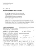
2.1. Turbo Codes. Focusing on the class of parallel concate-
nated convolutional code (PCCC) codes, Figure 1 shows the
encoder of the 3GPP-LTE turbo code. This is composed
of two stacked recursive systematic convolutional (RSC)
encoders, where the upper and lower units are fed by a
direct and an interleaved version of the information bits,
respectively. Interleaving among the bits of the information
word is performed in the block labeled Π in Figure 1.Each
RSC encoder is a particular linear feedback shift register
(LFSR) whose output bits c
i
, i = 0, 1, also called parity
bits, are a function of the status S of the register, of the
forward/backward connections (called taps), and of the input
bit u entering the encoder.
The performance of the turbo code closely depends on
the parameters of the constituent RSCs such as the number
of states, denoted as ν, and connection of the feed-back and
feed-forward taps. The number of states ν is linked to the
number of memory elements in the RSC, also referred to as
the constraint length L (L
= 4intheexampleofFigure 1),
through the relationship ν
= 2
L−1
.
The encoding process of the RSC can be effectively
represented by resorting to the so-called trellis graph,
reported in Figure 2 for the 3GPP-LTE encoder. This is a
diagram showing the evolution in time of the LFSR state and
describing the transitions (also referred to as edges) between
pairs of consecutive states: as shown in Figure 2,everyedge
is labeled with the pair of transmitted information symbols
that caused the transition and the parity bits output by the
encoder. So the RSC encoding process of a given information
word can be followed as a specific path on the trellis.
Aiming at enhanced error correction capabilities, M-ary
turbo codes have become widely used in recent communica-
tion standards after their introduction in the early 2000s [23].
In this case, each information symbol can assume M>2
values (M
= 2 corresponds to a binary code) that can be
expressed on m bits, so that M
= 2
m
. Standards such as DVB-
RCS and WiMAX define duo-binary turbo codes (m
= 2,
M
= 4), and an example of a duo-binary encoder is shown
in Figure 3.HighervaluesofM would further improve the
error-correction performance but are not of practical use due
to the excessive complexity of the related decoding algorithm.
EURASIP Journal on Advances in Signal Processing 3
0/00
0/00
0/00
1/11
1/11
0/00
0/10
1/01
1/01
1/01
0/10
0/10
0/10
1/11
1/11
1/01
s0
s1
s2
s3
s4
s5
s6
s7
s0
s1
s2
s3
s4
s5
s6
s7
s0
s1
s2
s3
s4
s5
s6
s7
k −1 kk+1
t
Figure 2: Example of an 8-state trellis diagram.
Duo-binary RSC
u
k,0
u
k,1
c
k,0
c
k,1
+
+
+
+
+
++
(a) Duo-binary RSC encoder
RSC
duo-binary
encoder
RSC
duo-binary
encoder
u
k,0
u
k,1
c
k,0
c
k,1
c
k,2
c
k,3
c
k,4
c
k,5
Π
(b) Duo-binary PCCC encoder
Figure 3: The WiMAX turbo encoder.
2.2. LDPC Codes. LDPC codes are linear block codes defined
by a sparse matrix H known as parity-check matrix, and x
is a valid codeword if belongs to the null space or kernel of
H,thatis,Hx
T
= 0. The parity-check matrix has a number
of columns N equal to the bits in the transmitted codeword
and a number of rows M equaltothenumberofparity-
check constraints, where P
= N − M is the number of parity
bits added by the LDPC encoder. Each row of the matrix
describes a parity-check constraint, with the convention that
the element h
i,j
set to “1” means that the jth bit of the
codeword participates into the ith parity-check constraint.
LDPC codes can be also described by means of a bi-
partite graph known as Tanner graph [24] which is arranged
in variable nodes (VNs), represented with circles, and check
nodes (CNs), represented with squares. Each VN represents
C
0
C
1
C
P−1
.
.
.
b
0
b
2
b
3
b
N−1
.
.
.
Figure 4: Example of a Tanner graph.
a bit of the transmitted codeword and corresponds to a col-
umn of H, while a CN represents a parity-check constraint,
that is, a row of H. A connection between variable and check
nodes, referred to as edge, corresponds to a “1” of the parity-
check matrix and graphically links a parity-check constraint
to a bit in the codeword. The number of edges connected
to a VN (CN) is known as variable node degree, d
v
(check
node degree, d
c
). An example of a Tanner graph is shown in
Figure 4.
As far as the design of the parity-check matrix is con-
cerned, it heavily affects both the error correction perfor-
mance and the complexity of the LDPC decoder. Hence,
joint code-decoder design techniques are usually applied
[25]. Following this route, a particular class of architecture-
aware- (AA-LDPC) codes [26] is currently being adopted
by all modern communication standards specifying LDPC
codes. The underlying idea is the arrangement of 1s in
the parity-check matrix according to patterns that ease
the parallelization of the decoding operations. Therefore,
the parity-check matrix is partitioned in smaller squared
matrices that can be either permutations or cyclic shifts of
the unit matrix called circulants [27]. Figure 5 shows the
prototype matrix of the WiMAX LDPC code 2/3a with length
2304: it is partitioned in Z
×Z matrices with Z = 96, where a
null entry corresponds to the all 0 matrix, while a nonnull
entry specifies the rotation (left-shift) applied to the unit
matrix.
3. Maximum A Posteriori Decoding of
Channels Codes
The BCJR algorithm [28] provides the common framework
to the decoding of turbo and LDPC codes as it is applied to
the decoding of the two component RSC codes of a turbo
code as well as to the parity-check update of an LDPC code.
3.1. The BCJR Decoding Algorithm. Figure 6 summarizes the
notation used in the BCJR decoding algorithm of an M-ary
convolutional code (M
= 2
m
). In particular,
(i) e is the oriented edge connecting the starting state
S
S
(e)totheendingstateS
E
(e), S
S
(e)
e
→ S
E
(e);
4 EURASIP Journal on Advances in Signal Processing
01 345678 91011 131415 1718 19 20 2221 23
0
1
2
3
4
5
6
7
0
0
0
0
0
0
0
00
0
0
00
0
3
3
1
2
2
0
34
7
3
0
36
1
10
1
18
2
0
12
2
15
40
3
15
2
13
19
24
3
6
17
8
39
20
6
10
29
14
38
0
10
20
36
21
45
35
25
37
21
5
4
20
0
6
6
4
14
30
3
36
14
1
1
1
1
1
1
1
1
3
1
8
9
1
28
0
28
12 16
H =
=
96 ×96 identity matrix rotated by r
= 96 ×96 zero matrix
r
.
.
.
Figure 5: Prototype matrix of WiMAX 2/3a LDPC code with length 2304 (Z = 96). Different block sizes are obtained with Z ranging from
24 to 96 in steps of 4 and rotations derived from the code with length 2304 after simple modulo or scaling operations (refer to [6]forfurther
details).
S
s
S
e
e
u(e)/c(e)
Figure 6: BCJR notation on the trellis.
(ii) u(e) is the information symbol related to edge e,
drawn from the alphabet U
={0, 1, , M −1},with
M
= 2
m
;
(iii) c(e) is the coded symbol associated to edge e,and
c
i
(e)istheith bit in c(e), with i = 0,1, ,n − 1.
So, against m information bits encoded in the symbol u,
n
≥ m coded bits are generated, and the ratio r = m/n is
referred to as the rate of the code.
Being a particular form of MAP decoding, the BCJR algo-
rithm aims at the maximization of the a posteriori probability
of the transmitted bit, given the observation of the received
codeword in noise. For an efficient implementation, the algo-
rithm is formulated in terms of reliability messages having
the form of log-likelihood ratios (LLRs). Given the M-ary
random variable x with values in X
={x
0
, x
1
, , x
M−1
},its
LLR is defined as
LLR
(
x
= x
i
)
˙
=log
P
(
x
= x
i
)
P
(
x = x
0
)
,(1)
where P(
·) denotes the probability mass function and i =
1, 2, ,M − 1. In (1), x
0
is used as the reference symbol for
normalization, so that only M
− 1 LLRs are associated to an
M-ary random variable.
Borrowing a notation from [4], the BCJR algorithm
involves the following quantities:
(i) λ
ch
k,i
is the channel a priori information for the coded
bit c
i
at time k,withi = 0,1, , n − 1andk =
0, 1, ,N − 1; being the input of the algorithm, λ
ch
k,i
is also referred to as input LLR;
(ii) γ
k
(c(e)) (or simply γ
k
(e)) is the cumulative metric
associated to the coded symbol c(e)ontheedgee at
time k; γ
k
(c(e)) is also referred to as branch metric;
(iii) λ
I
k
(u(e)) (or simply λ
I
k
(e)) is the a priori information
associated to the information symbol u(e)onthe
edge e at time k;
(iv) λ
O
k
(u(e)) (or simply λ
O
k
(e)) is the a posteriori extrinsic
information associated to the to information symbol
u(e)ontheedgee at time k;
(v) Λ
APP
k
(u(e)) (or simply Λ
APP
k
(e)) is the a posteriri
probability (APP) associated to the information
symbol u(e)ontheedgee at time k.
The BCJR algorithm first computes the branch-metric
γ
k
(e)as
γ
k
(
e
)
=
n−1
i=0
c
i
(
e
)
·λ
ch
k,i
(2)
with k
= 0, 1, , N − 1thetrellisindex.
EURASIP Journal on Advances in Signal Processing 5
Along with the a priori extrinsic information λ
I
k
(e), the
branch-metric γ
k
(e) drives the forward and backward recur-
sions α
and β
, computed in the log-domain according to
α
k+1
(
S
i
)
= max
∗
e:S
E
(
e
)
=S
i
α
k
(
S
S
(
e
))
+ γ
k
(
e
)
+ λ
I
k
(
e
)
,
β
k
(
S
i
)
= max
∗
e:S
S
(
e
)
=S
i
β
k+1
(
S
E
(
e
))
+ γ
k
(
e
)
+ λ
I
k
(
e
)
,
(3)
where the max
∗
(a, b)operatorisdefinedas
max
∗
(
a, b
)
˙
=log
e
a
+ e
b
=
max
(
a, b
)
+ log
1+e
−|a−b|
.
(4)
However, the max
∗
can be approximated with a simpler
max operation for a lower complexity implementation; in
this case the decoding algorithm is referred to as max-log-
MAP [4].
The forward (backward) recursion α (β)in(3)isevalu-
ated over the set of the edges e with ending (starting) state
S
i
at time k +1(k) and is initialized with α
0
= α
init
(β
N
= β
init
), at k = 0(k = N). Indeed, the initialization
value depends on the selected termination strategy, and it is
[1/ν, ,1/ν] for codes not terminated and is [1, 0, ,0]for
0-tail terminated codes, while for tail biting or circular codes
it is used to propagate the value reached by either the forward
or backward recursion at the previous iteration.
The state-metric recursions in (3)areintheformof
logarithm of probabilities, and to increase the numerical
robustness of the algorithm [14, 15], they are normalized
with respect to the value taken by a reference state, typically
the “zero” state S
0
, as in a regular LLR. This corresponds to
the following subtractions:
α
k
(
S
i
)
= α
k
(
S
i
)
−α
k
(
S
0
)
,
β
k
(
S
i
)
= β
k
(
S
i
)
−β
k
(
S
0
)
(5)
with i
= 0, 1, , ν −1.
Once the state-metric recursions are available, the a pos-
teriori estimation of the information symbol u is derived as
λ
O
k
(
u
i
)
= max
∗
e:u(e)=u
i
α
k
(
S
S
(
e
))
+ γ
k
(
e
)
+ β
k+1
(
S
E
(
e
))
−
max
∗
e:u(e)=u
0
α
k
(
S
S
(
e
))
+ γ
k
(
e
)
+ β
k+1
(
S
E
(
e
))
.
(6)
Being not directly connected to the input a priori mes-
sage λ
I
k
(e), the APP output λ
O
k
(u
i
)issaidtobeextrinsic.
3.2. The Turbo Decoding Principle. The turbo decoding algo-
rithm is achieved as the direct application of the BCJR
algorithm to both of its constituent RSC codes, according
to the block diagram of Figure 7. The two BCJR decoders
are the soft-in soft-out (SISO) units labeled SISO
1and
SISO
2, and the algorithm evolves as the iterative exchange
of extrinsic messages that are the a posteriori outputs of the
SISO engines.
The algorithm is fed with the channel a priori estimations
λ
ch
k,i
, in the form of LLR and computed according to (1)for
λ
ch
k,i
λ
ch
Π(k,i)
SISO 1
SISO
2
λ
I
(c)
λ
I
(u)
λ
O
(u)
λ
ext,1
k
Π
Π
Π
−1
λ
ext,1
Π(k)
λ
ext,2
Π(k)
λ
ext,2
k
+
λ
APP
k
λ
I
(u)
λ
I
(c)
λ
O
(u)
Figure 7: Decoding of PCCC codes: the turbo principle.
binary variables (M = 2). The output of SISO 1, called λ
ext,1
in Figure 7,isscrambledaccordingtotheinterleavinglaw
Π before being passed to SISO
2 as a priori information.
The latter also receives a scrambled version of the channel a
priori estimations λ
ch
k,i
and outputs the a posteriori reliability
messages λ
ext,2
. After inverse scrambling, these go back to
SISO
1 as refined a priori estimations about the transmitted
symbols.
As shown in Figure 7, the output of the turbo decoder,
that is, the a posteriori estimation of the transmitted symbol,
is given by the sum of the two extr insic messages output by
the SISO units. In formula,
Λ
APP
k
(
u
i
)
= λ
ext,1
k
(
u
i
)
+ λ
ext,2
k
(
u
i
)
(7)
with u
i
∈ U ={u
0
, u
1
, , u
M−1
} and k = 0, 1, , K − 1.
3.3. MAP Decoding of LDPC Codes. The MAP decoding algo-
rithm of LDPC codes is commonly referred to as belief
propagation (BP) or more generally message passing (MP)
algorithm [29]. BP has been proved to be optimal if the
graph of the code does not contain cycles, that is, consecutive
nodes connected in a closed chain, but it can still be used
and considered as a reference for practical codes with cycles.
In this case the sequence of the elaborations, referred to as
schedule,considerablyaffects the performance both in terms
of convergence speed and error correction rate.
The most straightforward schedule is the two-phase or
flooding schedule (FS) [30], which proceeds through two
consecutive phases, where all parity-check nodes first and all
variable nodes then are updated in sequence.
A more powerful schedule is the so-called shuffled or lay-
ered schedule [26, 30–32]. Compared to FS, shuffled sched-
ules almost double the decoding convergence speed, both
for codes with cycles and cycle-free [33]; this is achieved
by looking at the code as the connection of smaller super-
codes [26]orlayers [31], exchanging reliability messages.
Specifically, a posteriori messages are made available to the
next layers immediately after computation and not at next
iteration like in FS. Layers can either be sets of consecutive
CNsorVNs,and,accordingly,CN-centric (or horizontal)
or VN-centric (or vertical) algorithms have been defined in
[30, 32].
6 EURASIP Journal on Advances in Signal Processing
0/0 0/0 0/0 0/0 0/0
0/0 0/0 0/0
1/1
1/1
1/1
1/1
1/1
1/1 1/11/1
Even parity
Odd parity
S
0
S
0
S
0
S
0
S
0
S
0
S
1
S
1
S
1
S
1
Figure 8: Two-state trellis representation of a parity-check con-
straint with d
c
= 5.
3.3.1. Horizontal Layered Decoding. The HLD algorithm up-
dates the parity-check constraints sequentially around the
parity-check matrix. The key feature of HLD is the contin-
uous update, during decoding, of a cumulative metric y
n
associated to every VN in the code, n = 0, 1, , N − 1, and
called soft output (SO).
The update of CN m,withm
= 0,1, , M − 1, is based
on the availability of variable-to-check (vtoc) messages μ
n,m
directed from VN n to CN m and computed as
μ
(q)
m,n
= y
(q)
n
−
(q)
n,m
,(8)
where
(q)
n,m
is the check-to-variable (ctov) propagated by CN
m toward VN n at previous iteration, n
∈ N
m
denotes the set
of VNs connected to CN m,andq
= 0, 1, , N
it,max
−1isthe
iteration index.
Refined ctov messages
(q+1)
n,m
are produced as a result of
the check-node update, and, based on these, the set of SOs
involved in CN m,thatis,y
n
with n ∈ N
m
, is updated
according to
y
(q+1)
n
= μ
(q)
m,n
+
(q+1)
m,n
= y
(q)
n
−
(q)
n,m
+
(q+1)
m,n
. (9)
Thanks to the mechanism described in (8)and(9),
check-node operations always rely on up-to-date SOs, which
explains the increased convergence speed of HLD-shuffled
schedule.
The HLD algorithm is initialized at iteration q
= 0with
y
(0)
n
= λ
ch
n
,
(0)
m,n
= 0,
(10)
where λ
ch
n
is the LLR of the a priori channel estimation of the
received bits in noise, m
= 0, 1, ,M −1andn ∈ N
m
.
3.3.2. Check-Node Update. As far as the check-node update is
concerned, it is shown in [26] that a parity-check constraint
can be viewed as a 2-state convolutional code, where one state
is associated to even parity (S
0
) and the other to odd parity
(S
1
). The block size of the equivalent code is then equal to
the CN degree d
c
, and an example of its trellis representation
is given in Figure 8.
This analogy allows the BCJR algorithm to be also em-
ployed for parity-check updates of LDPC codes, and the re-
sulting decoding algorithm is known as turbo decoding
message passing (TDMP) [26]. The algorithm is fed with
vtoc messages as a priori information and produces ctov
messages as a posteriori outputs, with no branch metric from
the channel. So, in the update of CN m,thestate-metric
recursions are simplified into
α
k+1
= max
∗
α
k
, μ
(q)
m,n
−
max
∗
α
k
+ μ
(q)
m,n
,0
,
β
k
= max
∗
β
k+1
, μ
(q)
m,n
−
max
∗
β
k+1
+ μ
(q)
m,n
,0
,
(11)
where k
= 1, 2, ,d
c
(m)−1istherecursionstep,withd
c
(m)
being the degree of CN m,andn
= N
m
(k) is the index of the
VN involved at step k. The recursions in (11) are initialized
with α
0
= 1andβ
d
c
= 1.
Then, the computation of a posteriori extrinsic informa-
tion in (6)canbereworkedintheform
(q+1)
m,n
= max
∗
α
k
, β
k+1
−
max
∗
α
k
+ β
k+1
,0
(12)
with k
= 0, 1, , d
c
(m) −1andn = N
m
(k).
4. Fixed-Point Models
Givenapositionalnumericsysteminbaseδ,thefixed-point
representation X of a real (i.e., floating-point) signal x
∈
is expressed as
X
=
N
I
−1
n=0
a
n
δ
n
+
N
F
n=1
b
n
δ
−n
, (13)
where N
I
(N
F
) is the number of integer (fractional) digits
a
n
(b
n
), drawn from the set D ={0,1, , δ − 1}.Overall,
N
x
= N
I
+ N
F
digits are used to represent x.
The multiplication of (13)bythefactorδ
N
F
,alsoreferred
to as scaling factor, is practical to get rid of the decimal point
and is effective for the implementation of fixed-point DSP
or VLSI systems. Focusing on binary systems with δ
= 2, X
becomes an integer number in the form
X
=
N
x
−1
n=0
x
n
2
n
, (14)
where x
n
, n = 0, 1, ,N
x
− 1 are the binary digits of
the integer representation of x,withx
n
= b
N
F
−n
for n =
0, 1, ,N
F
− 1andx
n
= a
n−N
F
for n = N
F
, N
F
+1, , N
F
+
N
I
−1.
4.1. Conversion Law. Given a signal x defined in the domain
of reals, that is, x
∈ ,itsfixed-pointcounterpartX on
N
x
bits is now derived. As only a limited number of bits
is available, the domain of x needs to be constrained to an
interval of
,say[−A, A]. So a preventive saturation of the
signal in the range [
−A, A] must be performed, and the value
of A will be referred to as dynamic range in the remainder of
this paper.
EURASIP Journal on Advances in Signal Processing 7
X
2
Nx−1
−1
2
1
x
−2
Nx−1
+1
−2
−1
Δ
x
A2Δ
x
Δ
x
−A −2Δ
x
−Δ
x
Figure 9: Staircase conversion function from floating- to fixed-
point signals.
The operation of fixed-point conversion can be done ac-
cording to the following transformation:
X
= min
2
N
x
−1
−1,
x
Δ
x
+0.5
, x ≥ 0,
X
= max
−
2
N
x
−1
+1,
x
Δ
x
−0.5
, x<0,
(15)
where Δ
x
= 2A/(2
N
− 1) is the quantization step, that is, the
maximum difference between two different floating-point
values that are mapped onto the same fixed-point symbol
X.ThevalueofΔ
x
is a measure of the resolution of the
representation, that is, is the weight of the least significant
bit (LSB) x
0
of X.
Note that (15) not only performs the quantization of the
input signal, but it also limits its domain to the interval
[
−A, A], as shown in Figure 9, as values greater (less) than A
(
−A) are saturated to the biggest positive (smallest negative)
level 2
N
x
−1
−1(−2
N
x
−1
−1).
In (15), only 2
N
x
−1 fixed-point levels are used (the cod-
omain of the transformation function is symmetrical with
respect to the level 0); this choice prevents the algorithm
from drifting toward negative levels, which otherwise would
be systematically advantaged as also noted in [15].
So the pair (A, N
x
) fully defines the quantization of the
floating-point signal x, providing the dynamic range and the
weight of the LSB Δ
x
used for its representation.
This approach is similar to that described in [15]for
the quantization of input LLRs and is more flexible than
that generally adopted in the literature [14, 17–22], where
the fixed-point format is specified by the pair (N
I
: N
F
),
disregarding the dynamic range of the underlying real signal.
In other words, the dynamic range of the real signal is often
put in the form A
= 2
N
I
−1
and is limited to a power of
two. On the contrary, our approach comes through this
restriction, and it is applied to every internal fixed-point
elaboration.
4.2. Fixed-Point Turbo Decoding. The complete scheme of
the fixed-point SISO decoder is shown in Figure 10.The
algorithms described in Section 3.1 are reformulated in
fixed-point domain to involve operations among integers.
Following a cascade approach, all the involved operations
are converted into their fixed-point counterpart one after the
other.
4.2.1. Channel A Priori Information. Channel LLRs are
quantized according to (15) using the threshold A
λ
ch
and N
λ
ch
bits.
4.2.2. Branch Metric. The computation of γ
k
(e)asin(2)in-
volves the summation of n channel a priori reliabilities λ
ch
k,i
,
i
= 0, 1, , n − 1. So, in the worst case, where they all sum
coherently, it holds γ
k
(e) = n · A
λ
ch
, and the fixed-point
counterpart Γ of γ needs to be represented with
A
γ
= n ·A
λ
ch
,
N
γ
= N
λ
ch
+
log
2
n
.
(16)
4.2.3. max
∗
Operator. The operation z = max
∗
(x, y)implies
thecomputationofthemaxoftwosignalsx and y,andthe
addition of a correction term in the range ]0,log2]; hence,
thedynamicrangeofthez is upper bounded by
A
z
= max
A
x
, A
y
+ log 2. (17)
In order to let the comparison be possible, the fixed-point
counterparts of x and y, X and Y , respectively, must have
the same resolution, that is, Δ
x
= Δ
y
= Δ; holding this, the
number of bits to represent z can be derived from definition
of Δ as
2
N
z
=
2A
z
Δ
+1
=
2A
Δ
+
2 log 2
Δ
+1
=
2
N
−1
+
2 log 2
Δ
+1
= 2
N
1+
log 2
A
,
(18)
where A ˙
=max(A
x
, A
y
)andN ˙=max(N
x
, N
y
). Then, assum-
ing that A>log 2, as it is generally the case, expression (18)
gives
N
z
=
log
2
2
N
1+
log 2
A
=
N +1. (19)
However, (18)and(19) strictly hold when x
= A
x
=
y = A
y
= A, when the contribution of the correction term
is maximum; beside this very unlikely case, the additional
bit required in (19) is not really exploited, and the use of
A
z
= max(A
x
, A
y
) is generally enough, so that the result can
be saturated on N
z
= N bits. This approximation yields a
very little loss of information and so has negligible impact on
the algorithm performance. Therefore, the fixed-point max
∗
operation becomes
Z
= max
∗
(
X, Y
)
= min{max
(
X, Y
)
+LUT
(
D
)
, L}, (20)
where L
= 2
N−1
− 1 is the saturation threshold. In (20),
the correction term is quantized using the same resolution
Δ and is stored in a look-up table (LUT) addressed with
D
=|X −Y|.
8 EURASIP Journal on Advances in Signal Processing
λ
ch
N
λ
λ-MEM
N
λ
Branch
metric
Γ
N
γ
α/β-MEM
M
α
M
α
A
mem
LSL
T
α
LSR
T
α
Extr-APP unit
α/β state-metric recursion unit
N
λ
+
+
+ M
max
∗
max
∗
M
+
+
M +1
M
N
α
A
N
α
M = ceil (log 2{A
γ
+ A
α
+ A
λ
/2
Sλ
})
+
+
+
N
Λ
−1
max
∗
max
∗
N
Λ
−1
N
Λ
−1
+
+
N
Λ
Λ
LSR
T
Λ
M
Λ
Λ-MEM
M
Λ
Λ
mem
LSL
T
λ
M
Λ
+ T
Λ
Figure 10: Fixed-point model of the SISO engine in a turbo decoder.
4.2.4. A Posteriori Extrinsic Information. Since a posteriori
extrinsic reliabilities and forward/backward recursions are
mutually dependent through the iterative turbo principle,
their fixed-point representation can be studied under the
assumption that the state-metric recursions are represented
on N
α
= N
β
= N
γ
+ k bits, with k any integer. From (6), the
dynamic range of λ
O
is upper bounded by
A
λ
O
=
A
α
+ A
γ
+ A
β
−
−
A
α
−A
γ
−A
β
=
2 ·
2A
α
+ A
γ
=
2A
γ
·
1+2
k+1
,
(21)
where it has been exploited that A
α
= 2
k
A
γ
and A
α
= A
β
.
The full precision representation of λ
O
can be obtained
using N
λ
O
=log
2
(2A
λ
O
/Δ
λ
O
+1) bits, which gives
N
λ
O
= 1+N
γ
+
log
2
1+2
k+1
=
1+N
γ
+
max
∗
2
(
0, k +1
)
,
(22)
where the function max
∗
2
is the two-base max
∗
operator
defined as max
∗
2
(a, b)˙=max(a, b) + log
2
(1 + 2
−|a−b|
). The
following cases can be distinguished:
(a) k
≥ 0: it is easy to prove that max
∗
2
(0, k+1)=k +2,
so that N
λ
O
= N
γ
+ k +3= N
α
+3;
(b) k<0: now it is
max
∗
2
(0, k +1)=1andN
λ
O
=
N
γ
+2= N
α
+2−k.
In both cases N
λ
O
is a known function of N
α
and N
γ
,that
is, of N
α
and k.
4.2.5. State-Metric Recursions. Because of its recursive com-
putation, the magnitude of forward/backward recursions
would steadily grow proceeding along the trellis unless
it is controlled by means of saturation. Under the same
hypothesis of Section 4.2.4,thatis,N
α
= N
γ
+ k,thegrowth
of state metrics after one update step of (3)and(5) is upper
bounded by
2
A
α
+ A
γ
+ A
λ
I
=
2A
α
2+2
−k
+
A
λ
I
A
α
, (23)
where the a priori information λ
I
is indeed the a posteriori
output of the companion decoder, so that A
λ
I
= A
λ
O
.Substi-
tuting (21)in(23), the latter becomes
2A
α
1+2
−k
+2k
−1
·2
1−k
=
2
5+2
−k
+2
1−k
A
α
, (24)
meaning that the dynamic range of α would increase by the
factor 2(5 + 3
· 2
−k
) after every recursion step. This would
result in the addition of 1 +
log
2
(5 + 3 · 2
−k
) bits. Again,
two cases can be distinguished:
(a) k
≥ 0: the term (5+3·2
−k
) falls in the range from 5 to
8, resulting in the addition of 4 bits at each recursion
step;
(b) k<0: the term
log
2
(5 + 3 ·2
−k
) evaluates to 2 −k,
and overall 3
−k more bits are added at every step.
So the saturation of 4 or 3
−k bits, respectively, prevents
the uncontrolled growth of state metrics, hence represented
with (A
α
, N
α
). In [14, 15], bounds are provided for the
dynamic range of state-metric recursions, used to dimension
the internal precision of the SISO engine. On the contrary,
in the described approach the resolution of state-metric
recursion is a free input of the model and is controlled by
means of saturation. As also noted in [14], the precision of
state-metric recursions is inherently linked to that of branch
metrics and extrinsic messages, and if they are different,
scaling of the signals participating in the update must be
considered. This is achieved by means of shifting, used to
re-align the precision used on different signals; in terms of
quantization step Δ, the involved signals stay then in a ratio
of a power-of-two.
EURASIP Journal on Advances in Signal Processing 9
4.3. Fixed-Point LDPC Decoding. The fixed-point model of
a decoder of LDPC codes is derived following a similar
cascaded approach, and its scheme is reported in Figure 11.
The model allows the analysis of the independent effect
on performance of the representation of three different
signals, input a priori LLR, ctov messages, and state-metric
recursions within check-node updates.
4.3.1. Computation of Variable to Check Messages. The com-
putation of variable to check messages μ according to (8)
involves SOs and ctov messages.
Let input LLRs be quantized with (A
λ
, N
λ
)andctov
messages with (A
, N
), and let Δ
λ
and Δ
denote the
respective resolutions. Then, let the ratio ρ
= Δ
λ
/Δ
be
constrained to be a power of two. This assumption reduces
the number of independent variables in the model (only
three out of the four variables A
λ
, N
λ
, A
,andN
are actually
independent), but it is also the only viable solution for a
practical implementation of the algorithm.
If ρ>1, that is, when a finer resolution is used on ctov
messages, channel a priori LLRs need to be left shifted by
σ
λ
= log
2
(ρ) bits to be brought on the same resolution of
ctov messages, which in turn are not shifted (σ
= 0); in the
other case, no shift is needed on input LLRs (σ
= 0), while
ctov messages should be left shifted by σ
=−log
2
(ρ)bits.
As channel a priori LLRs are used to initialize SOs, the
two signals have the same resolution, that is, Δ
y
= Δ
λ
.
Therefore, the same relationship between the resolution of
ctov messages and input LLRs holds between ctov messages
and SOs. In view of this, SOs are initialized with a scaled
version of input LLRs (see the input right-shift by σ
λ
in
Figure 11(b)) so that data stored or retrieved from the λ/SO
memory use the same resolution of ctov messages. This
allows the direct subtraction Y
− E to compute fixed-point
vtoc messages.
Once available, vtoc messages are saturated in two differ-
ent ways, on N
μ
bits on the input of the CN update unit and
on N
ν
bits for the SO update in (9).
4.3.2. Update of Soft Outputs. The sum in (9) is performed
between updated ctov messages E and vtoc messages M
saturated on N
ν
, and its output is saturated to N
y
bits. As the
SOisalwaysequaltothesumofd
v
ctov messages entering a
given VN, the following relationship holds:
N
y
= N
+
log
2
d
v,max
, (25)
where d
v,max
is the maximum VN degree in the code. How-
ever, lower-complexity solutions can be investigated, where
SOs are saturated on fewer bits than in (25).
4.3.3. State-Metric Recursions. Expression (11)combines
vtoc messages with recursion metrics, and, similarly to the
computation of vtoc messages, different resolutions of the
two signals can be considered. Again, the ratio ρ
= Δ
/Δ
α
is constrained to be a power of two. As before, ρ is used to
align the fixed-point representation M and A of μ and α,
respectively, so that M is shifted by σ
μ
= log
2
(ρ)ifρ>1and
by σ
μ
= 0 otherwise; dually, A is shifted by σ
α
=−log
2
(ρ)if
ρ<1andbyσ
α
= 0 otherwise. So the fixed-point sum α + μ
in (11) becomes
A
·2
σ
α
+ M · 2
σ
μ
(26)
as also shown in Figure 11(a).
The remainder of the algorithm can be quantized in a
very similar way to that followed for turbo decoders, with
some simplifications. As also shown in Figure 11(a),ifwe
define B ˙
=max{N
α
+ σ
α
, N
μ
+ σ
μ
},thenewvalueofA is
represented on B +1bits,and,afterrightshiftbyσ
α
bits,
it is saturated to the desired number of bits N
α
.
4.3.4. APP Check to Variable Messages. With reference to
Figure 11(a), check to variable messages are computed with
the recursion metrics taken from memory, where they are
represented on M
α
bits. So the full-precision representation
of (12) can be represented on M
α
+2 bits. Then, countershifts
are performed (left shift by σ
α
and right-shift by σ
)inorder
to go back to the resolution of ctov messages, and the final
saturation restores the representation on N
bits.
4.4. Memory Size Reduction. Practical implementations of
turbo and LDPC codes decoders are based on the extensive
use of memory as a means to exchange extrinsic messages
(turbo decoders), to accumulate the output estimation
(LDPC decoders), and to store intermediate results (state-
metric recursions in turbo and LDPC decoders, ctov mes-
sages in LDPC decoders). It follows that the overall decoder
complexity is heavily dominated by memory, and techniques
such as truncation of the least significant bits (LSBs) or
saturation of the most significant bits (MSBs) are very
effective to limit the size of data stored in memory. However,
the use of saturation is preferable, as it reduces not only
the size of memory but also that of the data paths accessing
the memory unit. On the contrary, data truncated before
storage in memory need to be left shifted after retrieval from
memory to restore the original resolution (or weight of the
LSB Δ) and data paths do not benefit of any reduction in
size.
With reference to signal x, the notation T
x
and S
x
will
denote in the remainder of this paper the number of LSBs
truncated or MSBs saturated before storage in memory,
respectively.
Regarding the fixed-point turbo decoder, truncation
and saturation are performed on the state-metric recursions
stored in the α/β-MEM memory (T
α
and S
α
bits, resp.) and
on the a posteriori extrinsic information stored in the Λ-
MEM memory (T
Λ
and S
Λ
bits, resp.), as shown in Figure 10.
In the LDPC decoder, truncation is operated on ctov
messages (T
bits), on SOs (T
y
bits), and on state-metric
recursions (T
α
bits); as shown in Figure 11, these signals are
countershifted (left shift) just after retrieval from memory.
Then, saturations are performed on ctov messages (saturated
on M
bits) and α/β recursions (saturated on M
α
bits), while
SOs do not need any further saturation after their computa-
tion.
10 EURASIP Journal on Advances in Signal Processing
LSR
T
α
α/β-MEM
LSL
T
α
LSL
T
α
LSL
σ
μ
max
∗
max
∗
max
∗
max
∗
LSR
σ
α
LSL
σ
α
LSR
σ
+ σ
μ
LSL
σ
α
M
N
μ
M
α
M
α
M
α
M
α
+ T
α
M
α
+ T
α
N
μ
+ σ
μ
B −1
B
B
B +1
+
+
+
+
B +1
−σ
α
N
α
A/B
α/β state-metric recursion unit
N
α
+ σ
α
N
μ
+ σ
μ
0
A
B
A
B
+
+
+
+
M
α
N
α
0
N
α
N
α
+1
N
α
+1
N
α
+2 N
α
+2+σ
α
−S
N
E
Extr-APP check-to-variable unit
B = max{N
μ
+ σ
μ
,+N
α
+ σ
α
}+1
(a) 2-state BCJR decoder: fixed-point model
LSR
σ
λ
LSL
T
γ
LSR
T
γ
λ/SO-MEM
Λ
Y
mem
2-state BCJR
check-node
processor
LSR
T
LSL
T
N
λ
N
λ
+ σ
λ
Y
N
y
M
EN
y
+ σ
λ
+1
N
y
−T
y
y
N
y
M
N
υ
N
υ
M
N
μ
ME
N
N
E
mem
M
M
M
+ T
+
−
+
+
-MEM
(b) Layered decoding of LDPC codes: fixed-point model
Figure 11: The fixed-point model of LDPC codes decoding.
Table 1: Reference codes for the simulation scenario.
Standard Code Size (m)Length(K)Rate(R)IterationsN
it
3GPP-LTE Turbo 1 1504 1/3 10
WiMAX Turbo 2 480 1/2 10
WiMAX LDPC 1 1056 2/3b 15
5. Simulation Results
The error correction performance and implementation loss
(IL) of the fixed-point models developed in Section 4 have
been assessed by means of simulation. A full communica-
tion system complete of encoder, modulator, transmission
over AWGN channel, demodulator, and decoder has been
described in C++, and the two parametric fixed-point
models have been implemented as user-configurable C++
classes and methods.
Three different codes have been considered as a bench-
mark for the developed models, two turbo codes (a 3GPP-
LTE binary code and a WiMAX duo-binary code) and one
LDPC code (a WiMAX code), and their parameters are
summarized in Ta b l e 1. Their fixed-point performance has
been measured in the form of FER curves versus the signal to
noise ratio (SNR) E
b
/N
0
.
5.1. Turbo Codes Performance. The first critical design issue
is the identification of an optimal value for the input
dynamic range A
λ
ch
. Figure 12 shows the FER performance
for different values of A
λ
ch
. As a design constraint for a low-
complexity implementation, the input LLRs λ
ch
were coded
on N
λ
ch
= 5 bits while the forward/backward metrics were
represented on a large number of bits (N
α
= 16) so that the
IL is only due to the quantization of the inputs λ
ch
.
Focusing on the 3GPP-LTE code (left-most bundle of
curves in Figure 12), the smaller the value of A
ch
λ
, the smaller
the IL; the case A
ch
λ
= 10 corresponds to an impairment
below 0.1 dB with respect to the floating point reference
model, while further increasing the dynamic range yields
to very coarse resolution Δ
λ
ch
, which results in considerable
losses, especially at low E
b
/N
0
.
Conversely, the WiMAX code (right-most curves of
Figure 12) seems to be less sensitive to variations of A
λ
ch
,
the maximum impairment being about 0.15 dB for A
λ
ch
≥
12. This can be explained with the increased robustness to
channel noise offered by duo-binary codes, paid at the cost
of a bigger computational effort in the decoding algorithm.
Although Figure 12 seems to allow the use of A
λ
ch
= 5,
this value corresponds to a very rough quantization of
the channel LLRs, where several floating point samples are
saturated to the levels
±A
λ
ch
. Then, the coarser quantization
of the remainder of the algorithm can yield to additional
EURASIP Journal on Advances in Signal Processing 11
3.532.521.510.50
E
b
/N
0
10
−6
10
−5
10
−4
10
−3
10
−2
10
−1
10
0
FER
Floating point
A
= 5
A
= 8
A
= 10
A
= 12
A
= 15
Input dynamic analysis of 3GPP-LTE
and WiMAX turbo codes
3GPP-LTE WiMAX
Figure 12: Dynamic range analysis for N
λ
ch
= 5bits.
impairments due to the quantization noise, which can result
in flattening the FER curve (error floor). In view of this, the
value A
λ
ch
= 10 is cautiously selected for the next analysis.
Note that this kind of analysis was not feasible with the
quantization scheme generally adopted in the literature, or
at least with a very coarser step, being A
λ
ch
constrained to
powers of two.
Figure 13 shows the FER performance for different values
of the fixed-point parameters defined in Section 4.2 and
described with the triplet (N
λ
ch
, N
α
, N
Λ
).
Focusing on the 3GPP-LTE code, it turns out that no
impairment is observed by saturating three bits on the
extrinsic reliabilities (S
Λ
= 3) when N
α
= 7, while the
saturation of only 1 bit of the recursion metrics (S
α
= 1,
N
α
= 6) results in an IL of about 0.18 dB at high E
b
/N
0
.
Not surprisingly, the truncation of either recursion metrics
(T
α
= 1) or extrinsic reliabilities (T
Λ
= 1) slightly spoils the
FER performance at low E
b
/N
0
, where the LSBs bear the most
of the information, while the loss becomes almost negligible
at high E
b
/N
0
. Finally, aiming at a very low-complexity
solution, recursions and extrinsic metrics can be represented
on N
α
= N
Λ
= 6withanILof0.3dBathighE
b
/N
0
.
AsfarastheWiMAXcodeisconcerned,therobustness
of duo-binary codes is once again confirmed by a negligible
IL for all the simulated configurations. Indeed, only a slight
deviation at high E
b
/N
0
is shown when 1 bit of the recursion
metricsissaturated(S
α
= 1).
Ta b l e 2 summarizes the fixed-point parameters of two
optimal configurations, one (config. A) for better perform-
ances and the other (config. B) for lower complexity. The
32.521.510.50
E
b
/N
0
10
−6
10
−5
10
−4
10
−3
10
−2
10
−1
10
0
FER
Floating reference
(5,7,10)
(5,7,7)S
Λ
= 3
(5,7,6)S
Λ
= 3S
α
= 1
(5,7,7)S
Λ
= 3T
α
= 1
(5,6,6)S
Λ
= 3
(5,7,7)S
Λ
= 3T
Λ
= 1
Fixed-point performance of 3GPP-LTE
and WiMAX turbo codes
3GPP-LTE WiMAX
Figure 13: Analysis of the performance of the fixed-point turbo-
decoding algorithm.
Table 2: Optimal fixed-point parameters of the turbo decoder.
Signal Config. A Config. B
A priori channel LLR (10, 5) (10, 5)
Branch metric (RCS r
= 1/2) (20, 6) (20, 6)
State-metric recursions (40, 7) (20, 6)
Bits saturated on α/β (S
α
)22
A posteriori extrinsic messages (40, 7) (20, 6)
Bits saturated on extr. msg. (S
Λ
)3 3
latter has been further investigated to analyze the joint effect
of the input dynamic range and coarse quantization of
the algorithm on the overall error correction performance.
Figure 14 shows that the FER curves flatten for A
λ
ch
= 5
and A
λ
ch
= 8. This is a common issue to both binary
and duo-binary codes and is due to the combination of
the distortion introduced by the very strong saturation
on channel a priori inputs with the quantization noise
generated in the remainder of the algorithm. The value
A
λ
ch
= 10 yields the minimum convergence loss, but also
shows clear signs of a floor at very high E
b
/N
0
.Onthe
other hand, the use of A
λ
ch
= 12 and 15 prevents any floor
issue, but it is slightly penalizing in terms of convergence
abscissa, the IL being about 0.25 dB for LTE and 0.1 dB for
WiMAX.
12 EURASIP Journal on Advances in Signal Processing
43.532.521.510.50−0.5
E
b
/N
0
10
−6
10
−5
10
−4
10
−3
10
−2
10
−1
10
0
FER
Floating point
A
= 5
A
= 8
A
= 10
A
= 12
A
= 15
A posteriori dynamic analysis of
3GPP-LTE and WiMAX turbo codes
3GPP-LTE WiMAX
Figure 14: End-to-end fixed-point performance for different values
of A
λ
ch
.
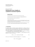
5.2. LDPC Codes Performance. The WiMAX LDPC code with
rate 2/3 (class B) and N
= 1056 features a maximum VN
degree d
v,max
= 6 and a maximum CN degree d
c,max
= 11.
The effect of the quantization of the input LLRs is
analyzed in Figure 15, where the FER is plotted against the
dynamic range A
λ
ch
for three different values of N
λ
ch
,4,5,and
6 bits. The three curves are simulated at E
b
/N
0
= 3.25 dB,
along with the floating point reference (solid line). The value
A
λ
ch
= 10 represents the best solution with 4 and 5 bits,
while the use of A
λ
ch
= 12 is preferable for N
λ
ch
= 6bits.
However, aiming at a low-complexity implementation, the
scheme (10, 5) is retained for the next analysis.
An analysis similar to that of Figure 15 is repeated in
Figure 16 for the quantization of the state-metric recursions
within the CN processor; in this case, full FER curves are
plotted as a function of E
b
/N
0
, and, to get rid of the losses
due to the quantization of ctov and SO messages, a very fine
quantization is used for both signals, based on many bits and
very large dynamic ranges. In particular, the scheme (160, 12)
is used for ctov messages, while 3 more bits (d
v,max
= 6) were
allowed for SOs and N
y
= 15. Similarly, N
μ
= 15 was also
used for vtoc messages, and, overall, the remainder of the
algorithm was run in quasi-floating-point domain.
The curves in Figure 16 can be parted in three groups
with different resolutions of the state-metric recursions: the
first group contains the curves with (A
α
, N
α
) = (10, 6),
(20, 7), and (40, 8) (referred to as lsb-0.5 and shown in
dashed lines), the second group is for the curves (10, 5) and
(20, 6) (referred to as lsb-1,solidlines),andthethirdgroup
15141312111098765
Channel LLR dynamic range (A
llr
)
10
−6
10
−5
10
−4
10
−3
FER
Floating point
N
llr
= 4
N
llr
= 5
N
llr
= 6
WiMAX LDPC code (N
= 1056, r = 2/3b)
Figure 15: WiMAX LDPC code: effects of the quantization on input
LLRs.
contains the curves (20,5), (40, 6), and (80, 7) (referred to
as lsb-2, dotted lines). It is shown that for lsb-0.5, at least 7
or even 8 bits are required to get rid of any flattening issue;
for lsb-1, N
α
= 6 already provides good performances, while
lsb-2 needs at least 7 bits to get close to the floating point
reference. As a result, the scheme (20, 6) can be retained for
a low-complexity solution. These results agree with those
reported in [17, 18] about fixed-point turbo decoding.
The quantization of ctov, SO, and vtoc messages is
studied in Figure 17, where messages are on 5 bits (dashed
lines) or 6 bits (dotted lines). Regarding the representation
of SO, since d
v,max
= 6, 3 more bits are required in principle
(N
y
= N
+ 3), but smaller values of N
y
are also simulated.
Similarly, starting from the case N
ν
= N
y
,lower-complexity
solutions with N
ν
<N
y
are also investigated.
When ctov messages are represented on 5 bits and SOs
on 8, the use of A
= 20 results in a considerable IL, greater
than 0.3 dB, due to the very coarse quantization; on the other
hand, the IL is greatly reduced with A
= 10, but the curves
flatten at high SNR, due to the limit imposed to the dynamic
range of ctov messages. Further reducing the number of bits
of SO or vtoc only worsens this situation.
Figure 17 shows that better performance is achieved with
N
= 6andA
= 20, in line with the observations in [20,
21]. In this case, the curve with SO and vtoc on 8 bits stays
very close to the floating point reference curve, the IL being
smaller than 0.05 dB, while the saturation of only 1 bit either
on vtoc (curve (20, 6)[8, 7]) or on SO (curve (20, 6)[7-7]) is
enough to spoil performance.
As a result of the above analysis, the value of the fixed-
point parameters yielding the best error correction perfor-
mance is summarized in Ta b l e 3 . Starting from this reference
configuration, Figure 18 shows the effects of the reductions
of α/β metrics, SO, and ctov before storage in memory. The
curves are labeled according to the value of the six parameters
[T
α
, S
α
], [T
, S
], and [T
y
, S
y
]. It is shown that, while 1 bit
EURASIP Journal on Advances in Signal Processing 13
3.63.12.62.11.6
E
b
/N
0
(dB)
10
−6
10
−5
10
−4
10
−3
10
−2
10
−1
10
0
FER
Floating point
(10, 6)
(20, 7)
(40, 8)
(10, 5)
(20, 6)
(20, 5)
(40, 6)
(80, 7)
WiMAX LDPC 1056 r
=2/3b:
λ
= (10, 5), = (160, 12)
Figure 16: WiMAX LDPC code: effects of the quantization on the
state-metric recursions within the CN processor.
Table 3: Optimal fixed-point parameters of the LDPC decoder.
Signal Dynamic range (A)No.ofbits(N)
A priori channel LLR 10 5
Vtoc for CN update 20 6
Vtoc for SO update 80 8
State-metric recursions 20 6
Ctov extrinsic messages 20 6
SO (so) metrics 80 8
can be truncated on state-metric recursions with negligible
losses (T
α
= 1), the IL is more relevant when 1 bit is saturated
(S
α
= 1, i.e., M
α
= 5). A similar result holds for ctov
messages, where the case T
= 1 is tolerated with minimum
losses, while S
= 1 is not. Regarding SOs, truncation of only
one bit (T
y
= 1) utterly corrupts the decoding performance.
6. Summary and Conclusion
This paper has described the fixed-point model of a decoder
for turbo and LDPC codes, derived in a unified framework
based on the use of the BCJR decoding algorithm.
Comparing the results of Tables 2 and 3, the following
conclusions hold:
(i) a priori channel reliability can be represented with
(10, 5) with negligible losses for both codes;
3.63.12.62.11.6
E
b
/N
0
(dB)
10
−6
10
−5
10
−4
10
−3
10
−2
10
−1
10
0
FER
Floating point
= (20, 5),[8, 8]
= (20, 5),[7, 7]
= (10, 5),[8, 8]
= (10, 5),[7, 7]
= (10, 5),[6, 6]
= (20, 6),[8, 8]
= (20, 6),[8, 7]
= (20, 6),[7, 7]
WiMAX LDPC 1056 r
=2/3b:
λ
= (10, 5), α = (20, 6)
Figure 17: WiMAX LDPC code: effects of the quantization of check
to variable, soft-output, and variable to check messages.
(ii) state-metric recursions need the representation (20,
6) or (40, 7) for turbo codes, while (20, 6) is enough
forLDPCcodes.Thiscanbeexplainedwiththe
smallernumberofedges(2)inthetrellisofanLDPC
code compared with a turbo code (2 in binary, 4 in
duo-binary codes) and with the absence of branch
metrics in LDPC decoding;
(iii) a posteriori extrinsic messages of SISO decoders are
on 6 or 7 bits, while soft outputs of LPDC codes
need 8 bits. Considering that the turbo decoder APP
output is the sum of two extrinsic messages (see (7)),
the results are in agreement;
(iv) check to variable messages of LDPC decoding need
the quantization (20, 6), and no counterpart exists in
turbo decoders.
These results are in line with those contained in [15, 16,
18, 19, 34] for turbo decoders or in [20–22] for decoders of
LDPC codes. Compared with [14], state-metric recursions
need significantly fewer bits than in the bound given, which
evaluates to 9 bits for the considered codes. Also, the single-
SISO architecture in [14] needs 7 bits for extrinsic messages,
in agreement with our results.
The fixed-point quantization law described in this paper,
based on the dynamic range (A) of the underlying (floating)
signal and number of bits (or, equivalently, the resolution
Δ), has allowed the analysis of their independent effects
on performance. As opposed to the approach generally
14 EURASIP Journal on Advances in Signal Processing
3.63.12.62.11.6
E
b
/N
0
(dB)
10
−6
10
−5
10
−4
10
−3
10
−2
10
−1
10
0
FER
Floating point
α : [0, 0],
: [0, 0], y : [0, 0]
α : [1, 0],
: [0, 0], y : [0, 0]
α : [0, 1],
: [0, 0], y : [0, 0]
α : [0, 0],
: [1, 0], y : [0, 0]
α : [0, 0],
: [0, 1], y : [0, 0]
α : [0, 0],
: [0, 0], y : [1, 0]
WiMAX LDPC 1056 r
= 2/3b: N
λ
= 5,
N
= 6, N
y
= 8, N
μ
= 8, N
α
= 6
Figure 18: WiMAX LDPC code: effects of saturation and trunca-
tion before memorization.
adopted in the literature (see [14, 16, 18, 19, 34]), the
dynamic range of the floating signal and the number of bits
of its representation have been left independent, and the
dynamic ranges not constrained to a power of two. This
solution, also adopted in [15], has been extensively exploited
in the proposed models, not only for the quantization of
input signals but also for every internal fixed-point opera-
tion.
Also, the model described in this paper has overcome the
limitation common to similar works in the field and related
to the use of the same resolution Δ for every fixed-point
elaboration, such computation of a priori channel messages,
state-metric recursions, and ctov messages in an LDPC
decoder. Furthermore, the model has allowed the exploration
of memory reduction techniques based on truncation and
saturation, and simulations have shown that 1 bit can be
truncated on state-metric recursions before memorization in
both turbo and LDPC decoders.
A final remark relates to the optimal choice of the fixed-
point parameters, which does not have absolute validity,
rather it depends on the operating point of the decoder
and so on the desired error-correction rate; systems or
applications operating above, next to, or below the error floor
of the FER curve need indeed different values of the fixed-
point parameters. To this extent, our results extend down to
the beginning of the error-floor, above FER 10
−6
.
References
[1] R. Gallager, Low-density parity-check codes, Ph.D. dissertation,
Massachusetts Institutes of Technology, 1960.
[2] S. Benedetto, D. Divsalar, G. Montorsi, and F. Pollara, “Serial
concatenation of interleaved codes: performance analysis,
design and iterative decoding,” IEEE Transactions on Informa-
tion Theory, vol. 44, no. 3, pp. 909–926, 1998.
[3] C. Berrou, A. Glavieux, and P. Thitimajshima, “Near shannon
limit error-correcting coding and decoding: turbo codes,” in
Proceedings of the IEEE International Conference on Communi-
cations, vol. 2, pp. 1064–1070, May 1993.
[4] S. Benedetto, G. Montorsi, D. Divsalar, and F. Pollara, “Soft-
input softoutput modules for the construction and distributed
iterative decoding of code networks,” European Transactions on
Telecommunications, vol. 9, no. 2, pp. 155–172, 1998.
[5] “Local and metropolitan area networks–specific require-
ments—part 11: wireless LAN medium access control (MAC)
and physical layer (PHY) specifications amendment 5:
enhancements for higher throughput,” IEEE 802.11n
TM
-2009,
October 2009.
[6] “IEEE standard for local and metropolitan area networks—
part 16: Air interface for broadband wireless access systems,”
IEEE Computer Society, IEEE Std 802.16
TM
-2009, May 2009.
[7] “Universal Mobile Telecommunication system,” European
Telecommunications Standards Institute, ETSI UMTS
TM
-
2000, June 2000.
[8] “3rd Generation Partnership Project—Technical Specification
Group Radio Access Network- High Speed Downlink Packet
Access (HSDPA)-Overall description,” 3rd Gener. Partnership
Project, September 2009.
[9] “Evolved Universal Terrestrial Radio Access (E-UTRA),” 3rd
Gener. Partnership Project 2, June 2009.
[10] “Satellite digital video broadcasting of second generation
(DVB-S2),” ETSI Standard EN302307, February 2005.
[11] “Digital Video Broadcasting (DVB); interaction channel for
satellite distribution Systems,” European Telecommunications
Standards Institute, DVB-RCS
TM
-2002, November 2002.
[12] “Framing structure, channel coding and modulation for
satellite services to handheld devices (SH) below 3 GHz,”
Digital Video Broadcasting group, DVB-SH
TM
-2007, July
2007.
[13] “Physical Layer and Management Parameters for 10 Gb/s Op-
eration, Type 10GBASE-T,” 802.3 Working Group, September
2006.
[14] G. Montorsi and S. Benedetto, “Design of fixed-point iterative
decoders for concatenated codes with interleavers,” IEEE
Journal on Selected Areas in Communications,vol.19,no.5,pp.
871–882, 2001.
[15] E. Boutillon, C. Douillard, and G. Montorsi, “Iterative decod-
ing of concatenated convolutional codes: implementation
issues,” Proceedings of the IEEE, vol. 95, no. 6, pp. 1201–1227,
2007.
[16] E. Boutillon, W. J. Gross, and P. G. Gulak, “VLSI architectures
for the MAP algorithm,” IEEE Transactions on Communica-
tions, vol. 51, no. 2, pp. 175–185, 2003.
[17] T. K. Blankenship and B. Classon, “Fixed-point performance
of low-complexity turbo decoding algorithms,” in Proceedings
of the 53rd IEEE Vehicular Technology Conference (VTC ’01),
vol. 2, pp. 1483–1487, May 2001.
[18] M. A. Castellon, I. J. Fair, and D. G. Elliott, “Fixed-point turbo
decoder implementation suitable for embedded applications,”
in Proceedings of the Canadian Conference on Electrical and
Computer Engineering, pp. 1065–1068, May 2005.
EURASIP Journal on Advances in Signal Processing 15
[19] A. Morales-Cort
´
es, R. Parra-Michel, L. F. Gonzalez-Perez,
and C. T. Gabriela, “Finite precision analysis of the 3GPP
standard turbo decoder for fixed-point implementation in
FPGA devices,” in Proceedings of the International Conference
on Reconfigurable Computing and FPGAs (ReConFig ’08),pp.
43–48, December 2008.
[20] T. Zhang, Z. Wang, and K. Parhi, “On finite precision imple-
mentation of low density parity check codes decoder,” in
Proceedings of the IEEE International Symposium on Circuits
and systems (ISCAS ’01), vol. 4, pp. 202–205, May 2001.
[21] Z. Zhang, L. Dolecek, M. Wainwright, V. Anantharam, and
B. Nikoli
´
c, “Quantization effects in low-density parity-check
decoders,” in Proceedings of the IEEE International Conference
on Communications (ICC ’07), pp. 6231–6237, June 2007.
[22] R. Zarubica, R. Hinton, S. G. Wilson, and E. K. Hall, “Efficient
quantization schemes for LDPC decoders,” in Proceedings of
the IEEE Military Communications Conference (MILCOM ’08),
pp. 1–5, November 2008.
[23]C.Berrou,M.Jezquel,C.Douillard,andS.Keroudan,“The
advantages of non-binary turbo codes,” in Proceedings of the
IEEE Information Theory Workshop, pp. 61–62, September
2001.
[24] R. M. Tanner, “A recursive approach to low complexity codes,”
IEEE Transactions on Information T heory,vol.27,no.5,pp.
533–547, 1981.
[25] E. Boutillon, J. Castura, and F. Kschischang, “Decoder-first
code design,” in Proceedings of the International Symposium on
Turbo Codes and Related Topics, pp. 459–462, September 2000.
[26] M. M. Mansour and N. R. Shanbhag, “High-throughput
LDPC decoders,” IEEE Transactions on Ver y Large Scale
Integration (VLSI) Systems, vol. 11, no. 6, pp. 976–996, 2003.
[27] H. Zhong and T. Zhang, “Block-LDPC: a practical LDPC
coding system design approach,” IEEE Transactions on Circuits
and Systems I, vol. 52, no. 4, pp. 766–775, 2005.
[28] L. R. Bahl, J. Cocke, F. Jelinek, and J. Raviv, “Optimal decoding
of linear codes for minimizing symbol error rate,” IEEE
Transactions on Information Theory, vol. 20, no. 2, pp. 284–
287, 1974.
[29] T. J. Richardson and R. L. Urbanke, “Efficient encoding of low-
density parity-check codes,” IEEE Transactions on Information
Theory, vol. 47, no. 2, pp. 638–656, 2001.
[30] F. Guilloud, E. Boutillon, J. Tousch, and J L. Danger, “Generic
description and synthesis of LDPC decoders,” IEEE Transac-
tions on Communications, vol. 55, no. 11, pp. 2084–2091, 2006.
[31] D. E. Hocevar, “A reduced complexity decoder architecture
via layered decoding of LDPC codes,” in Proceedings of
the IEEE Workshop on Signal Processing Systems Design and
Implementation (SISP ’04), pp. 107–112, October 2004.
[32] E. Sharon, S. Litsyn, and J. Goldberger, “An efficient message-
passing schedule for LDPC decoding,” in Proceedings of the
23rd IEEE C onvention of Electrical and Electronics Engineers in
Israel, pp. 223–226, September 2004.
[33] H. Kfir and I. Kanter, “Parallel versus sequential updating for
belief propagation decoding,” Physica A, vol. 330, no. 1-2, pp.
259–270, 2003.
[34] Y.Tong,T.H.Yeap,andJ.Y.Chouinard,“VHDLimplementa-
tion of a turbo decoder with log-MAP-based iterative decod-
ing,” IEEE Transactions on Instrumentation and Measurement,
vol. 53, no. 4, pp. 1268–1278, 2004.