Báo cáo hóa học: " Review Article Recent Advances in Real-Time Musical Effects, Synthesis, and Virtual Analog Models" pot
Bạn đang xem bản rút gọn của tài liệu. Xem và tải ngay bản đầy đủ của tài liệu tại đây (1.16 MB, 15 trang )
Hindawi Publishing Corporation
EURASIP Journal on Advances in Signal Pr ocessing
Volume 2011, Article ID 940784, 15 pages
doi:10.1155/2011/940784
Rev iew Ar ticle
Recent Advances in Real-Time Musical Effects,
Synthesis, and Virtual Analog Models
Jyri Pakarinen,
1
Ve sa V
¨
alim
¨
aki,
1
Federico Fontana,
2
Victor Lazzarini,
3
and Jonathan S. Abel
4
1
Department of Signal Processing and Acoustics, Aalto University School of Electrical Engineering, 02150 Espoo, Finland
2
Department of Mathematics and Computer Science, University of Udine, 33100 Udine, Italy
3
Sound and Music Technology Research Group, National University of Ireland, Maynooth, Ireland
4
CCRMA, Stanford University, Stanford, CA 94305-8180, USA
Correspondence should be addressed to Jyri Pakarinen, jyri.pakarinen@tkk.fi
Received 8 October 2010; Accepted 5 February 2011
Academic Editor: Mark Kahrs
Copyright © 2011 Jyri Pakarinen et al. This is an open access article distributed under the Creative Commons Attribution License,
which permits unrestricted use, distribution, and reproduction in any medium, provided the original work is properly cited.
This paper reviews some of the recent advances in real-time musical effects processing and synthesis. The main emphasis is on
virtual analog modeling, specifically digital emulation of vintage delay and reverberation effects, tube amplifiers, and voltage-
controlled filters. Additionally, adaptive effects algorithms and sound synthesis and processing languages are discussed.
1. Introduction
Real-time musical effects processing and synthesis play a
part in nearly all musical sounds encountered in the con-
temporary environment. Virtually all recorded or electrically
amplified music in the last few decades uses effects process-
ing, such as artificial reverberation or dynamic compression,
and synthetic instrument sounds play an increasingly larger
part in the total musical spectrum. Furthermore, the vast
majority of these effects are presently implemented using
digital signal processing (DSP), mainly due to the flexibility
and low cost of moder n digital devices. For live music, real-
time operation of these effects and synthesis algorithms is
obviously of paramount importance. However, also recorded
music typically requires real-time operation of these devices
and algorithms, because performers usually wish to hear the
final, processed sound of their instrument while playing.
The purpose of this article is to provide the reader with
an overview of some of the recent advances in this fascinating
and commercially active topic. An exhaustive review of
all novel real-time musical effects processing and synthesis
would fill a book. In fact, an earlier review on digital audio
effects can be found in the book [1] and in a recent book [2],
while reviews of virtual analog modeling and digital sound
synthesis can be found in articles [3]and[4], respectively.
A tutorial on virtual analog oscillator algorithms, which are
not tackled in this paper, has been written by V
¨
alim
¨
aki
and Huovilainen [5]. Also, musical synthesis and effects
applications for mobile devices have been reported in [6]. In
order to conveniently fit in a single journal article, a selection
of some of the most active subtopics under t his exciting
research field have been chosen for presentation here.
The organization of this review is as follows: adaptive
effects processing algorithms, such as the adaptive FM
technique, are reviewed in Section 2. Section 3 discusses the
emulation of vintage delay and reverberation effects, while
recent advances in tube amplifier emulation are studied
in Section 4. Real-time simulation of an interesting analog
effects device, the voltage-controlled filter, is rev iewed in
Section 5, and recent advances in sound synthesis and
processing languages are discussed in Section 6.Finally,
Section 7 concludes the review.
2. Adaptive Effects Processing
Many adaptive effects processing algorithms suitable for a
general input signal have been introduced during the past few
2 EURASIP Journal on Advances in Signal P rocessing
Delay
y(n)
x
(n)
Low pass
Mod. depth
Bias
(a)
y(n)
Delay
Pitch tracker
Mod.
depth
Sin osc
x
(n)
Low pass
(b)
y(n)
x
(n)
All pass
Mod.
depth
Low pass
(c)
y(n)
SDF
Mod.
depth
x
(n)
Low pass
(d)
Delay
y(n)
x
(n)
Low pass
Mod.
depth
High pass
(e)
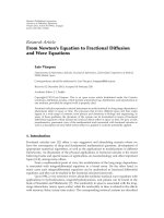
Figure 1: Recent adaptive effects processing structures: (a) self-modulating FM [7], (b) adaptive FM [8], (c) coefficient-modulated all-pass
filter [9], (d) coefficient-modulated spectral delay filter (SDF) [10], and (e) brassification [11].
years. The idea of an adaptive audio effect is not entirely new:
it has been possible for many years to control parameters
of an algorithm with a feature measured from the signal.
Still, it was found useful to give the name “Adaptive DAFx”
to this class of methods a few years ago [12], and since
then many papers belonging to this categor y have been
published. In this section, we briefly review some recent
methods belonging to this category of real-time musical
signal processing algorithms.
Audio-driven sound synthesis introduced by Poepel and
Dannenberg [7] is an example of a class of adaptive effects,
which goes so far as almost being a synthesis method rather
than a transformation of the input signal. In one example
application of this idea, Poepel and Dannenberg show how
FM (frequency modulation) synthesis can be modified by
deriving the modulation signal frequency by tracking the
pitch of an input signal. In this case, the input signal is
assumed to be a monophonic signal, such as a trumpet sound
picked up by a microphone. Poepel and Dannenberg also
describe an algorithm, which they call self-modulating FM.
In this method, the low-pass filtered input signal is used
as both modulation and carrier signal. The modulation is
realized by varying the delay-line length with the scaled low-
pass filtered input signal, see Figure 1(a) [13].
Lazzarini and his colleagues [8] extended the basic idea
of audio-driven synthesis to what they call adaptive FM
(AdFM). Poepel and Dannenberg had proposed a basic
modified FM synthesis method in which the modulator is
replaced with the input audio sig nal [7]. Lazzarini et al. [8]
reversed the roles of the modulator and the carrier so that
they use the input signal as the carrier. It is advantageous
to low-pass filter the carrier signal before modulating it,
since the spectrum of the signal will expand because of
frequency modulation and the output sound will otherwise
become very bright. T he pitch of the input signal, however,
is used to control the modulation frequency. In AdFM,
the modulation is implemented by moving the output tap
of a delay line at the modulation frequency, as shown in
Figure 1(b). A fractional delay filter is required to obtain
smooth delay variation [14]. The FM modulation index then
controls the width of this variation. An advantage of the
AdFM effect is that it retains the character of the input signal.
In one extreme, when the modulation d epth is set to zero,
the output signal will be identical to the (low-pass filtered)
input signal. By increasing the modulation index, the method
distorts the input signal so that it sounds much like an FM-
synthesized tone.
Extensions to these methods were presented in [15],
where the FM sidebands were split in four separate groups
(in combinations of upper/lower and even/odd), and in [16]
where asymmetric-spectra FM methods were introduced.
Finally, in [17] a modified FM version was presented
EURASIP Journal on Advances in Sig nal Processing 3
x
(n)
AP AP AP EQ
y(n)
M allpass filters
Optional
···
Figure 2: A spectral delay filter consists of a cascade of all-pass
filters (AP) and an optional equalizing filter (EQ) [18].
(a variant of FM based on modified Bessel coefficients). This
was complemented by an algorithm that allows transitions
between modified, asymmetrical, and classic FM for adaptive
applications.
An adaptive effect of a similar spirit as the audio-driven
approach and adaptive FM was introduced by Pekonen [9].
In his method, presented in Figure 1(c),theaudiosignalis
filtered with a first-order all-pass filter and the coefficient
of that all-pass filter is simultaneously varied with scaled
and possibly low-pass filtered version of the same inp ut
signal. This technique can be seen as signal-dependent phase
modulation and it introduces a distortion effect, but does not
require a table lookup, like waveshaping, or pitch tracking,
like AdFM.
It was shown recently by Lazzarini et al. [19] that the
choice of the all-pass filter structure affects considerably the
output signal in the time-varying case. It was found that the
direct form I structure has smaller transients with the same
input and coefficient modulation signals than two alternative
structures and, thus, this expression is recommended for use
in the future
y
(
n
)
= x
(
n − 1
)
− a
x
(
n
)
− y
(
n − 1
)
,
(1)
where x(n)andy( n) are, respectively, the input and output
signals of the all-pass filter and a is the all-pass filter
coefficient.
Kleimola and his colleagues [10] combined and
expanded further the idea of the signal-adaptive modulation
utilizing all-pass filters. In this coefficient-modulated
method, the input signal is fed through a chain of many
identical first-order all-pass filters while the coefficients
are modulated at the fundamental frequency of the input
signal. The chain of all-pass filters cascaded with an
optional equalizing filter, as shown in Figure 2, is called
aspectraldelayfilter[18]. A pitch tracking algorithm or
low-pass filtered input signal may be used as a modulator,
see Figure 1(d). The modulation of the common all-pass
filter coefficient introduces simultaneously frequency and
amplitude modulation e ffects [10].
The “brassifier” effect proposed by Cooper and Abel [11]
is another new technique that is closely related to the pre-
vious ones. It has been derived from the nonlinear acoustic
effect that takes place inside b rass musical instruments, when
the sound pressure becomes very large. In the “brassification”
algorithm, the input signal is scaled and is used to control
a fractional delay, which phase modulates the same input
signal. It can be seen that the brassification method differs
from the self-modulating FM method of Figure 1(a) in
its computation of the delay modulation and in that a
highpass filter is used as postprocessing. Similar methods
have previously been used in waveguide synthesis models
to obtain interesting acoustic-like effects, such as generic
amplitude-dependent nonlinear distortion [20], shock waves
in brass instruments [21–23], and tension-modulation in
string instruments [24, 25]. These methods aim at imple-
menting a passive nonlinearity [26]. All these nonlinear
effects are implemented by controlling the fractional delay
with values of the signal samples contained in the delay line.
In the practical implementation of the brassification
method, the input signal propagates in a long delay line and
the output is read with an FIR interpolation filter, such as
linear interpolation or fourth-order Lagrange inter polation.
The input signal can be optionally low-pass filtered prior to
the delay-line input to emphasize its low-frequency content
and the output signal of the delay line can be high-pass
filtered to compensate the low-pass filtering, as shown in
Figure 1(e).
3. Vintage Delay and Reverber a tion Effects
Processor Emulation
Digital emulation of vintage electronic and electromechani-
cal effects processors has received a lot of attention recently.
While their controls and sonics are very desirable, and
the convenience of a software implementation of benefit,
these processors often present signal processing challenges
making real-time implementation difficult. In t his section,
we focus on recent signal processing techniques for real-
time implementation of vintage delay and reverberation
effects. We first consider techniques to emulate reverberation
chambers, and spring and plate reverberators, and then focus
on tape delay, bucket brigade delays, and the Leslie speaker.
3.1. Efficient Low-Latency Convolution. Bill Putnam, Sr. is
credited with introducing artificial reverberation to record-
ing [27]. The method involved placing a loudspeaker and
microphone in a specially constructed reverberation cham-
ber made of acoustically reflective material and having a
shape lacking parallel surfaces. The system is essentially
linear and time invariant and, therefore, characterized by
its impulse response. Convolving the input signal with the
chamber impulse response is a natural choice, as the synthe-
sized system response will be psychoacoustically identical to
that of the measured space.
However, t ypical room impulse responses have long
decay times and a real-time implementation cannot afford
the latency incurred using standard overlap-add processing
[28]. Gardner [29]andMcGrath[30] noted that if the
impulse responses were divided into two sections, the
computation would be nearly doubled, but the latency would
be halved. A ccordingly, if the impulse response head is
recursively divided in two so that the impulse response
section lengths were [L, L,2L,4L,8L, ], the initial part of
the impulse response would provide the desired low latency,
while the longer blocks comprising the latter portion of the
impulse response would be efficiently computed.
4 EURASIP Journal on Advances in Signal P rocessing
Garcia in [31] noted that processors could efficiently
implement the needed multiply-accumulate operations, but
that the addressing involved slowed FFT operations for
longer block sizes. If a number of blocks were of the same
length, then they could all share the input signal block
forward transform. For example, if the impulse responses
were divided into sections of identical block lengths, only one
forward transform and only one inverse transform would
be needed for each block of input signal block processed.
Garcia showed that dividing the impulse response into a few
sections, each of which is divided into equal-length blocks,
produces great computational savings while maintaining a
low latency.
Finally, it should be pointed out that an efficient method
for performing a low-latency convolution, dividing the
impulse response into equal-length blocks and using a two-
dimensional FFT, was introduced by Hurchalla in [32].
3.2. Hybrid Reverberation Methods. Reverberation impulse
responses contain a set of early arrivals, often including a
direct path, followed by a noise-like late field. The late field is
characterized by Gaussian noise having an evolving spectrum
P(ω, t)[33, 34]
P
(
ω, t
)
=
q
(
ω
)
2
exp
−
t
τ
(
ω
)
,(2)
where the square magnitude
|q(ω)|
2
being the equalization
at time t
= 0, and τ(ω) defining the decay rate as a function
of frequency ω. This late field is reproduced by the feedback
delay network (FDN) structure introduced by Jot in the early
1990s [34]. There, a signal is delayed by a set of delay lines
of incommensurate lengths, filtered according to the desired
decay times τ(ω), mixed via an orthonormal mixing matrix,
and fed back.
However, when modeling a particular room impulse
response, the psychoacoustically important impulse response
onset is not preserved. To overcome this difficulty, Stewart
and Murphy [35] proposed a hybrid structure. A short
convolutional section exactly reproduces the reverberation
onset, while an efficient FDN structure generates the late
field with a computational cost that does not depend on the
reverberation decay time. Stated mathematically, the hybrid
reverberator impulse response is the sum of that of the
convolutional section c(t) and that of the FDN section d(t)
h
(
t
)
= c
(
t
)
+ d
(
t
)
. (3)
The idea is then to adjust c(t)andd(t) so that the system
impulse response h(t) psychoacoustically approximates the
measured impulse response m(t). The convolutional section
may be taken directly from t he measured impulse response
onset, and the equalization and decay rates of the FDN
designed to match those of the measured late field response.
In doing this, however, two issues arise: one having to do with
the duration of the convolutional onset, and the other with
the cross-fade between the convolutional and FDN sections.
A q uantity measuring closeness to Gaussian statistics c alled
the normalized echo density (NED) has been shown to
predict perceived echo density. In [36], the convolutional
onset duration was given by the time at which the measured
and FDN impulse responses achieve the same NED.
Regarding controlling the energy profiles of the onset
and FDN components during the transition between the
two, reference [36] suggests unrolling the loop of the FDN
several times so that its impulse r esponse energy onset is
gradual. The convolutional response c(t)isthenwindowed
so that when it is summed with the FDN response d(t),
the resulting smoothed energy profile matches that of the
measured impulse response. While this method is very
effective, additional computational and memory resources
are used in unrolling the loop. In [37], a constant-power
cross-fade is achieved by simply subtracting the unwanted
portion of the FDN response d(t) from the convolutional
response c(t).
The EMT 140 plate reverberator is a widely used
electromechanical reverberator, first introduced in the late
1950s. The EMT 140 consists of a large, thin, resonant
plate mounted under tension. A driver near the plate
center produces transverse mechanical disturbances which
propagate over the plate surface, and are detected by pickups
located toward the plate edges. A damping plate is positioned
near the signal plate and is used to control the low-frequency
decay time (see, e.g., [36]).
Bilbao [38] and Ar cas and Chaigne [39] have explored
the physics of plates and have developed finite difference
schemes for simulating their motion. However, there are
settings in which these schemes are impractical, and for
real-time implementation as a (linear, time-invariant) rever-
beration effect, an efficient hybrid reverberator is useful.
Here, the convolutional portion of the hybrid reverberator
captures the distinctive whip-like onset of the plate impulse
response, while the FDN reproduces the late-field decay,
fixing reverberation time as a function of the damping plate
setting.
3.3. Switched Convolution Reverberator. Both convolutional
and delay line-based reverberators have significant memory
requirements, convolutional reverberators needing a 60 dB
decay time worth of samples and delay network reverberators
requiring on the order of a second or two of sample memory.
A comb filter structure requires little memory and may
easily be designed to produce a pattern of echos having
the desired equalization and decay rate. However, it has a
constant, small echo density of one arrival per delay line
length. This may be improved by adding a convolution
with a noise sequence to the output. The resulting structure
produces the desired echo density and impulse response
spectrogram, and uses little memory—on the order of a few
tenths of a second. The difficulty is that its output contains
an undesired periodicity at the comb filter delay line length.
As proposed in [40] and developed in [41], the periodicity
may be reduced significantly by changing or “switching”
the noise filter impulse response o ver time. Furthermore, by
using velvet noise—a sequence of
{+1, 0, −1} samples [40]—
an efficient time-domain implementation is possible.
A hybrid switched convolution reverberator was devel-
oped in [42]forefficiently matching the psychoacoustics of
EURASIP Journal on Advances in Sig nal Processing 5
a measured impulse response. As above, the convolutional
portion of the system is taken from the impulse response
onset. However, here, the switched convolution reverberator
noisesequencesaredrawnfromthemeasuredimpulse
response itself. In this way, the character of the measured late
field is retained.
3.4. Spring Reverberators. Springs have been long used to
delay and reverberate audio-bandwidth s ignals. Hammond
introduced the spring reverberator in the late 1930s to
enhance the sound of his electronic organs [43], and,
since the 1960s with the introduction of torsionally driven
tensioned springs [44], they have been a staple of guitar
amps.
Modern spring reverbs consist of one or more springs
held under tension, and they are driven and picked up
torsionally from the spring ends. Spring mechanical distur-
bances propagate dispersively, and the primary torsional and
longitudinal modes propagate low frequencies faster than
high ones. Bilbao and Parker [45] have developed finite
difference methods based on Wittrick’s treatment of helical
coils [46], generating accurate simulations. An efficient
approximation, using the dispersive filter design method
described in [47]ispresentedin[48]. There, a bidirectional
waveguide implements the attenuation and dispersion seen
by torsional waves travelling along the spring. A similar
structure was used in [49] to model wave propagation along a
Slinky. In addition, an FDN structure was proposed in which
each delay line was made dispersive.
This model does not include the noise-like “wash”
component of the impulse response, which may be the result
of spring imperfections. In [50], an efficient waveguide-type
model is described in which a varying delay generates the
desired “wash.” Additionally, a simple, noniterative design
of high-order dispersive filters based on spectral delay filters
was proposed in [50].
3.5. Delay Effects. The Leslie speaker, a rotating horn housed
in a small cabinet [51–54], was often paired with a Ham-
mond B3 organ. As the horn rotates, the positions of the
direct path and reflections change, resulting in a varying
timbre and spreading of the spectral components, due to
Doppler shifts. Approaches to emulating the Leslie include
separately modeling each arrival with an interpolated write
according to the horn’s varying position, and a biquad
representing the horn radiation pattern [52]. In another
recent approach [54], impulse responses are tabulated as a
function of horn rotation angle. As the horn rotates, a time-
varying FIR filter is applied to the input, with each filter tap
drawn from a different table entry according to the horn’s
evolving rotational state. Rotation rates well into the audio
bands were produced.
Tape delays, including the Maestro Echoplex and Roland
SpaceEcho, are particularly challenging to model digitally.
Their signal flow is simple and includes a delay and feedback.
The feedback is often set to a value greater than one, causing
the unit to oscillate, repeatedly amplifying the applied input
or noise in the system. While the feedback loop electronics
includes a saturating nonlinearity, much of the sonic charac-
ter of these u nits arises from the tape transport m echanism,
which produces both quasiperiodic and stochastic compo-
nents, as described in [55, 56]. Finally, it should be pointed
out that the Echoplex uses a moveable record head to control
the delay. The record head is easily moved faster than the tape
speed, resulting in a “sonic boom”. In [55], an interpolated
write using a time-varying FIR antialiasing filter is proposed
to prevent aliasing of this infinite-bandwidth event.
Bucket brigade d elay lines have been widely used in
chorus and delay processors since the 1970s. A sample and
hold was used with a network of switched c apacitors to
delay an input signal according to an externally applied
clock. However, as the charge representing the input signal is
transferred from one capacitor to the next, a small amount
bleeds to adjacent capacitors, and the output acquires a
mild low-pass characteristic. In addition, while the charge is
propagating through the delay line, it decays to the substrate.
In this way, louder signals are distorted. A physical model of
the device is presented in [57].
4. Tube Amplifier Emulation
Digital emulation of tube amplifiers has become an active
area of commercial and academic interest during the last
fifteen years [ 58]. The main goal in tube emulation is to
produce flexible and realistic guitar amplifier simulation
algorithms, which faithfully reproduce the sonic character-
istics and parametric control of real vintage and modern
guitar amplifiers and effects. Furthermore, these dig ital
models should be computationally simple enough so that
several instances could be run simultaneously in real-time.
A recent review article [58] made an extensive survey
of the existing digital tube amplifier emulation methods.
The objective of the present section is to summarize the
emulation approaches published after the aforementioned
review.
4.1. Custom Nonlinear Solvers. Macak and Schimmel [59]
simulate the diode limiter circuit, commonly found in
many guitar distortion effects. They start with devising a
first-order IIR filter according to the linearized equivalent
circuit, after which the nonlinear effects are introduced by
allowing the variation of the filter coefficients. The implicit
nonlinear relation between the filter coefficients and its
output is tackled using two alternative approaches. In the first
approach, an additional unit delay is inserted into the system
by evaluating the filter coefficients using the filter output
at the previous sample. Obviously, this creates a significant
error when the signal is changing rapidly, as can happen
at hig h input levels, resulting in saturation. Thus, the first
approach needs a high sampling rate to perform correctly, so
that the signal value and system states do not change much
between successive samples. The second approach is to solve
the implicit nonlinearity using the Newton-Raphson method
and use the previous filter output only as an initial estimate
for the solver. Additionally, a nonlinear function is added for
6 EURASIP Journal on Advances in Signal P rocessing
Stage 1
Stage 2
(load)
Stage 2
Stage 3
(load)
Stage 3
Input
To the rest
of the circuitry
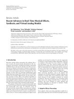
Figure 3: The preamplifier structure used in [60]. The interstage
loading effects are approximated by simulating a pair of amplifier
stages together and reading the output in between them. Thus, the
latter stage of this pair acts simply as a load for the first stage and
does not produce output.
saturating the estimate in order to accelerate the convergence
of the iteration.
In a later article [60], Macak and Schimmel introduce
an ordinary differential equation- (ODE-) based real-time
model of an entire guitar amplifier. Although some parts
of the amplifier are clearly oversimplified (ideal output
transformer, constant power amplifier load, ideal impedance
divider as the cathode follower), it is one of the most
complete real-time amplifier models published in academic
works. The ODEs for the tube stages are discretized using the
backwards Euler method, and the implicit nonlinearities are
approximated using the present input value and the previous
state. The individual tube nonlinearities are modeled using
Koren ’s equations [61], and the tone stack is implemented as
reported in [62]. The algorithm is reportedly implemented
as a VST-plugin.
The correct modeling of the mutual coupling between
amplifier stages is important for realistic emulation, but
efficient real-time simulation of this is a difficult task. On
the one hand, a full circuit simulation of the amplifier
circuitry provides a very accurate, although computationally
inefficient model. On the other hand, a block-based cascade
model with unidirectional signal flow can be implemented
very efficiently, but is incapable of modeling the coupling
effects.
An interesting hybrid approach has been used in [60],
where the mutual coupling between the preamp triode stages
is simulated by considering each pair of cascaded stages
separately. For example, the output of stage 1 is obtained by
simulating the cascaded stages 1 and 2 together, while the
output is read in between the stages, as illustrated in Figure 3.
Thus, the output of stage 2 is not used at this point, and
the stage 2 is only acting as a load for stage 1. The output
of stage 2 is similarly obtained by simulating the cascade
of stages 2 and 3 and reading the output between them.
Interestingly, a similar modeling approach has been used in
a recent commercial amplifier emulator [63].
4.2. State-Space Models. A promising state-space modeling
technique for real-time nonlinear circuit simulation, the DK
method, has been presented by Yeh and colleagues [64, 65].
It is based on the K method [66] introduced by Borin and
others in 2000, and augments it by automating the model
creation. Furthermore, the DK method discretizes the state
elements prior to solving the system equations in order to
avoid certain computability problems associated with the K
method. The nonlinear equations are solved during run-
time using Newton-Raphson iteration. In practice, with the
DK method, t he designer can obtain a digital model of a
circuit simply by writing its netlist—a well-known textual
representation of the circuit topology—and feeding it to the
model generator.
Interestingly, the DK method allows the separation of
the nonlinearity from the memory elements, removing the
need for run-time iteration and thus allowing an efficient
real-time implementation using look-up tables. However,
for the memory separation to work properly, the circuit
parameters should be held fixed during the simulation,
thus disabling run-time control of the knobs on the v irtual
system. Alternatively, control parameter v ariations can be
incorporated into the static nonlinearity by increasing its
dimension, which makes the look-up table interpolation
more challenging.
A variation to the DK method has been introduced by
Dempwolf et al. [67]. In their paper, the system equations
are derived manually, leading to more compact matrix repre-
sentations. Also the discretization procedure is different. As
a result, the method described in [67] is computationally less
expensive than the DK method, but the model generation
cannot be automated. The Marshall JCM900 preamp circuit
is used as a case study in [67], and the simulation results show
a good graphical and sonic match to measured data.
Another state-space representation for the 12AX7 triode
stage i s proposed by Cohen and H
´
elie [68], along w ith
a comparison of the traditional static model and a novel
dynamic model for the triode tube. In particular, Koren’s
static tube model [61] is augmented by adding the effect of
stray capacitance between the plate and the grid, a source of
the Miller effect in the amplifier circuit. An implicit numeri-
cal integration scheme is used for ensuring convergence, and
the algorithm is solved using the Newton-Raphson method.
The preamplifier model has been implemented as a real-time
VST-plugin. A single-ended guitar power amplifier model
using a linear output transformer has been reported in [69].
The pentode tube is simulated using Koren’s equations [61],
and the same state-space approac h as in [68]ischosenfor
modeling. Also in [69], the simulation is implemented in
real-time as a VST-plugin.
4.3. Wave-Digital Filter Models. The usability of wave digital
filters (WDFs) in the virtual analog context is discussed by
De Sanctis and Sarti in [70]. Importantly from the viewpoint
of amp emulation, different strategies for coping with
multiple nonlinearities and global feedback are reviewed.
Traditionally, implementing a circuit with multiple nonlinear
elements using WDFs requires special care. In [70], it is
suggested that the part of t he circuit containing multiple
nonlinearities would be implemented as a single multiport
nonlinearity, and the computability issues would be dealt
inside this multiport block, for example using iterative tech-
niques. This would essentially sacrifice some of the modular-
ity of the WDF representation for easier computability. The
consolidation of linear and time-invariant WDF elements
EURASIP Journal on Advances in Sig nal Processing 7
as larger blocks for increasing computational efficiency is
suggested already in an earlier work by Karjalainen [71].
A new WDF model of a triode stage has been introduced
in [72]. In contrast to the previous WDF triode stage [73],
this enhanced real-time model is capable of also simulating
the triode grid current, thus enabling the emulation of phe-
nomena such as interstage coupling and blocking distortion
[74]. The plate-to-cathode connection is simulated using
a nonlinear resistor implementing Koren’s equations [61],
while the grid-to-cathode connection is modeled with a tube
diode model. The implicit nonlinearities are solved by the
insertion of unit delays, so that there is no need for run-
time iteration. Although the artificial delays theoretically
compromise the modeling accuracy and model stability, in
practice the simulation results show an excellent fit to SPICE
simulations, and instability issues are not encountered for
realistic signal levels.
The output chain of a tube amplifier, consisting of a
single-ended-triode power amplifier stage, output trans-
former and a loudspeaker, is modeled using WDFs in [75].
The power amplifier stage uses the same triode model
as in [72], thus allowing the simulation of the coupling
between the power amp and loudspeaker. Linear equivalent
circuits are devised for the transformer and loudspeaker,
and the component values are obtained from datasheets and
electrical measurements. The simulation is implemented as
a computationally efficient fully parametric real-time model
using the BlockCompiler software [76], de veloped by Matti
Karjalainen.
4.4. Distortion Analysis. Since tube amplifier emulators are
designed to mimic the sonic properties of real amplifiers
and effects units, it is important for the system designer
to be able to carefully measure and analyze the distortion
behavior of real tube circuits. Although comparisons are
typically done by subjective listening, objective methods
for distortion analysis in tube amp emulation context have
recently been reported [77–80]. In [77], the parameter
variations on a highly simplified unidirectional model of
a tube amp with static nonlinearities were studied using
the exponential sweep analysis [81, 82]. In particular, the
shape of the static nonlinear curves and filter magnitude
responses wer e individually varied, and the resulting effects
on the output spectra with up to nine harmonic distortion
components were analyzed.
In [79, 80, 83], Nov
´
ak and colleagues use the exponential
sweep analysis in creating nonlinear polynomial models of
audio devices. More specifically, the nonlinear model, called
the generalized polynomial Hammerstein structure, consists
of a set of parallel branches w ith a power function and a
linear filter for each harmonic component. In [79], an audio
limiter effect is simulated, while two overdrive effects pedals
are analyzed and simulated in [80]. Reference [83]modelsan
overdrive pedal using a parallel Chebyshev polynomial and
filtering structure.
In [78], a software tool for distortion analysis is
presented and a VOX AC30 guitar amplifier together with
two commercial simulations are analyzed and compared.
The tool has five built-in analysis functions for measuring
different aspects of nonlinear distortion, including the
exponential sweep and dynamic intermodulation distortion
analysis [84], and additional user-defined analysis techniques
can be added using Matlab. The software is freely available
at .fi/publications/papers/DATK.
Finally, the use of nonlinear signal shaping algorithms
has also been re-evaluated in view of modern analysis and
modeling methods in [85]. Here the technique of phaseshap-
ing is studied as an alternative to the more traditional non-
linear waveshaping algorithms. Employing a recent spectral
analysis method, the Complex Spectral Phase Evolution
(CSPE) algorithm, the distortion characteristics of overdrive
effects are analyzed [86] and polynomial descriptions of
phase and wave shaping functions are obtained from phase
and amplitude harmonic data. The method outlined in that
work is capable of reproducing distortion effects both in
terms of their spectrum and waveform outputs.
5. Digital Voltage-Controlled Filters
The voltage-controlled filter (VCF) is a famous paradigm in
real-time sound processing. Not only has it been recognized
as a milestone in the history of electronic music, but in
an attempt to reformulate the challenging solutions in its
architecture in the digital domain, the various discrete-time
models that were proposed in the last fifteen years to simulate
the VCF have given rise to a curious thread of interesting
realizations.
Developed originally by Moog [87], the VCF is composed
of an RC ladder whose resistive part is formed by four tran-
sistor pairs in a differential configuration. These transistors
are kept forward biased by a current source, which sets the
cutoff frequency of the filter. The ladder’s output is fed back
to its input via a high-impedance amplifier in a way that
generates, in the cutoff region, oscillations whose amplitude
and persistence depend on a variable resistance that controls
the amount of feedback. In the limit of maximum feedback,
the VCF becomes an oscillator ringing at the cutoff frequency
irrespective of the input.
Both the bias current and the variable resistance are
user controls in Moog synthesizers, the former provided by
DC signal generators and low-frequency oscillators, as well
as by external signal sources, the latter by simply varying
the resistance through a knob. Sometimes musicians have
controlled the filter behavior by feeding musical signals of
sufficient amplitude that the bias current is affected and the
cutoff is varied in a complex interplay between synthesis and
control. An analogous effect is produced when the injected
currents contain frequency components that are high enough
to reach the filter output.
Finally, the VCF response is affected by the input
amplitude due to the many solid-state components in the
circuitry. Large amplitude signals are in fact distorted by
the transistors, giving rise to the characteristic nonlinear
behavior of this filter. A similar, but not identical, behavior
was exhibited by a VCF clone on board the EMS synthesizers,
employing diodes instead of transistors in the RC ladder [89].
8 EURASIP Journal on Advances in Signal P rocessing
In conclusion, the VCF has compelling ingredients
that make its simulation in the discrete-time especially
interesting: (i) nonlinear behavior and (ii) two-dimensional
continuous control, exerted by b oth parameter changes (i.e.,
the variable resistance governing the oscillatory behavior)
and control signals (the bias current setting the cutoff point).
As a result, it established a paradig m in virtual analog
modeling.
5.1. Linear Digital VCFs. Even the reproduction of the VCFs
linear behavior has to deal with the two-dimensional control
space and its effects in the output. The problem can be
further simplified by collapsing the current-based control
mechanism into a scalar parameter of cutoff frequency. Such
simplifications lead to the following transfer function:
H
(
s
)
=
{G
(
s
)
}
4
1+k{G
(
s
)
}
4
=
1
k + {1+s/ω
c
}
4
,(4)
in which frequency variable ω
c
sets the cutoff fr equency
and feedback gain k determines the oscillatory behavior
(i.e., resonance). The function G(s)
= ω
c
/(ω
c
+ s)models
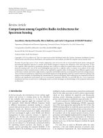
every single step of the ladder. Figure 4 shows, in dashed
lines, typical magnitude responses of the analog Moog VCF
obtained by plotting
|H(jω)| in audio frequency as by (4)
and, in solid lines, spectra of discrete-time impulse responses
after bilinear transformation of H(s)intoH(z) at 44.1 kHz,
respectively, for gains k equalto1,2,3,and4.Allresponses
have been plotted for cutoff frequencies f
c
= ω
c
/(2π)equal
to 0.1, 1, and 10 kHz [ 88].
Stilson and Smith, in their pioneering approach to the
linear modeling of the VCF [90], showed that the accurate
real-time computation of (4) in discrete time is problematic.
In fact, k and ω
c
merge into a bidimensional nonlinear
map while moving to the digital domain. On the other
hand, approximations of H(s) aiming at maintaining such
parameters decoupled in the discrete-time domain lead to
inaccurate responses as well as to mismatches of the c ut-off
frequency and persistence of the oscillations compared to the
analog case.
A step ahead in the linear VCF modeling has been
achieved by Fontana, who directly computed the delay-
free loop VCF structure arising from (4) and illustrated
in Figure 5 for convenience [88]. By employing a specific
procedure for the computation of delay-free loop filter
networks [91], the couple (ω
c
, k) in fact could be preserved in
the discrete-time domain without mixing the two parameters
together. In practice, this procedure allows to serialize the
computation of the four identical transfer functions G(z)
obtained by the bilinear transformation of G(s), indepen-
dently of the feedback gain k. Three look-up tables and a few
multiplications and additions are needed to obtain the feed-
back signal and the state variable values for each sampling
interval. This way, an accurate response, an independent and
continuous parametric control, and real-time operation are
all achieved at a fairly low computational cost.
5.2. Nonlinear Digital VCFs. The introduction of nonlin-
earities complicates the problem to a large extent. When
the nonlinear components, such as transistors or diodes, are
modeled, the simulation c an be developed starting from a
plethora of VCF circuit approximations. The final choice
often ends up on a mathematically tractable subset of such
components, each modeled with its own degree of detail,
allowing to establish a nonlinear differential state-space
representation for the whole system.
Furthermore, different techniques exist to solve the
nonlinear differential problem. Concerning the VCF, two
fundamental paradigms have been followed: the functional
paradigm, relying on Volterra expansions of the nonlineari-
ties, and the circuit-driven paradigm, based on the algebraic
solution of the nonlinear circuit. Both such paradigms yield
solutions that must be integrated numerically. By solving
simplified versions of the VCF in a different way, both of
them are prone to various typ es of inaccuracies.
Huovilainen, who chose to use a circuit-driven approach
[93], was probably the first to attempt a nonlinear solution
of the VCF. He derived an accurate model of the transistor -
basedRCladderaswellasofthefeedbackcircuit.Onthe
other hand, while proposing a numerical solution to this
model, he kept a fictitious unit delay in the resulting digital
structure to avoid costs and complications of an implicit
procedure for the feedback loop computation. The extra unit
delay in the feedback loop creates an error in parameter
accuracy, which increases with frequency. Huovilainen then
uses low-order polynomial correction functions for both the
cut-off frequency and the resonance parameter, thus still
reaching a desired accuracy [92].
Figure 6 shows a simplified version of Huovilainen’s
nonlinear digital Moog filter, in which only one nonlinear
function is used [92]. Huovilainen’s full Moog ladder model
contains five such functions: one for each first-or der section
and one for the feedback circuit. A hyperbolic tangent
is used as the nonlinear function in [93]. In a real-time
implementation, this would usually be implemented using
a look-up table. Alternatively, another similar smoothly
saturating function, such as a third-order polynomial, can
be used instead. Huovilainen’s nonlinear Moog filter self-
oscillates, when the feedback gain is set to a value of one
or larger. The saturating nonlinear function ensures that
the system cannot become unstable, because signal values
cannot grow freely. The simplified model of Figure 6 behaves
essentially in the same manner as the full model, but small
differences in their output signals can be observed. It remains
as an interesting future study to test with which input signals
and parameter setting their minor differences could be best
heard.
The Volterra approach was proposed by H
´
elie in 2006
[95]. This approach requires a particular ability to manip-
ulate Volterra kernels and to manage their instability in
presence of heavy distortion. Indeed, high distortion levels
can be generated by the VCF when fed large amplitude inputs
and for high values of k, that is, when the filter is set to
operate like a selective resonator or like an oscillator. In
a more recent development proposed by the same author
[96], sophisticated ad-hoc adaptations of the Volterra kernels
were set in an aim to model the transistors’ saturation o n a
sufficiently large amplitude range.
EURASIP Journal on Advances in Sig nal Processing 9
−60
−50
−40
−30
−20
−10
0
10
20
30
40
Frequency (Hz)
Magnitude (dB)
k = 1
10
1
10
2
10
3
10
4
(a)
k = 2
−60
−50
−40
−30
−20
−10
0
10
20
30
40
Frequency (Hz)
Magnitude (dB)
10
1
10
2
10
3
10
4
(b)
k = 3
−60
−50
−40
−30
−20
−10
0
10
20
30
40
Frequency (Hz)
Magnitude (dB)
10
1
10
2
10
3
10
4
(c)
k = 4
−60
−50
−40
−30
−20
−10
0
10
20
30
40
Frequency (Hz)
Magnitude (dB)
10
1
10
2
10
3
10
4
(d)
Figure 4: Magnitude responses of the analog linear Moog VCF (dashed line) and its digital version obtained by bilinear transformation at
44.1 kHz (solid line). Cut-off frequencies equal to 0.1, 1, and 10 kHz are plotted in each diagram [88].
x
(t)
G(s)
G(s)
G(s) G(s)
y(t)
k
−
+
Figure 5: Delay-free loop filter structure of the VCF.
In 2008, Civolani and Fontana devised a nonlinear state-
space representation of the diode-based EMS VCF out of
an Ebers-Moll approximation of the driving transistors [97].
This representation could be computed in real time by means
of a fourth-order Runge-Kutta numerical integration of the
nonlinear system. The model was later reformulated in terms
of a passive nonlinear analog filter network, which can readily
be turned into a passive discrete-time filter network through
z
−1
x
(n)
G(z)G(z)
G(z)
G(z)
y(n)
k
−
+
Nonlinearity
Fictitious delay
Figure 6: A simplified version of Huovilainen’s nonlinear digital
Moog filter [92].
any analog-to-digital transformation preserving passivity
[94]. The delay-free loops in the resulting digital network
were finally computed by repeatedly circulating the signal
along the loop until convergence, in practice implementing
a fixed-point numerical scheme.
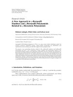
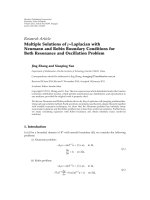
Figure 7 provides examples of responses computed by
the EMS VCF model when fed a large amplitude impulsive
input [94]. On the left, the impulse responses for increasing
10 EURASIP Journal on Advances in Signal Processing
10
1
10
2
10
3
10
4
−80
−60
−40
−20
0
20
40
60
80
Frequency (Hz)
Magnitude (dB)
(a)
10
1
10
2
10
3
10
4
−80
−60
−40
−20
0
20
40
60
80
Frequency (Hz)
Magnitude (dB)
(b)
Figure 7: Magnitude responses of the EMS VCF model for a 1 V impulsive input and cutoff frequency set to 0.1, 1, and 10 kHz. (a) k = 0
(bold), 8 (thin solid). (b) k
= 11. Sampling frequency set at 176.4 kHz [94].
values of k are illustrated at cut-off frequencies equal to
0.1, 1, and 10 kHz. On the right, the system behavior is
illustrated with the same cut-off frequencies and a very high
feedback gain. Comparison with Figure 4 helps to appreciate
the contribution of the distortion components to the output,
as well as their amount for changing values of the feedback
gain parameter. Also for reasons that are briefly explained at
the end of this section, Figure 7 does not include magnitude
spectra of output signals measured on a real EMS VCF, due
to the gap that still exists between the virtual analog model
and the reference filter.
5.3. Current Issues. The current Java implementation for
the PureData real-time environment [98] of the aforemen-
tioned delay-free loop filter network, obtained by bilinear
transformation of the state-space representation of the EMS
analog circuit [94], represents a highly sophisticated non-
commercial realization of a VCF software architecture in
terms of accuracy, moderate computational requirement,
continuous controllability of both ω
c
and k,andinter-
operability under all operating systems capable of running
PureData and its pdj libraries communicating with the Java
Virtual Machine. In spite of all these desirable properties, the
implementation leaves several issues open.
Especially some among such issues ask for a better
understanding and consequent design of the digital filter.
(i) The bias current has been modeled so far in terms
of a (concentrated) c ut-off frequency parameter. As
it has been previously explained, the analog VCF
cutoff is instead biased by a current signal that flows
across the filter together with the musical signal. The
subtle, but audible nuances resulting from the con-
tinuous interplay between such two signals, can be
reproduced only by substituting the cut-off frequency
parameter in the state-space representation with one
more system variable, accounting for the bias current.
Moreover, this generalization may provide a powerful
control for musicians who appreciate the effects
resulting from this interplay .
(ii) Although designed to have low or no interference
with the RC ladder, the feedback circuit has a non-
negligible coupling effect with the feedforward chain.
As we could directly assess on a diode-based VCF
on board an EMS synthesizer during a systematic
measurement session, the leaks affecting the feedback
amplifier in fact give rise to responses that are
often quite far from the “ideal” VCF behavior.
Even when the feedback gain is set to zero, this
circuit exhibits a nonnull current absorption that
changes the otherwise stable fourth-order low-pass
RC characteristics. Techniques aiming at improving
the accuracy of the feedback amplifier would require
to individually model at least some of its transistors,
with consequences on the model complexity and
computation time that cannot be predicted at the
moment.
The next generation of virtual analog VCFs may provide
answers to the above open issues.
6. Synthesis and Processing Languages
Languages for synthesis and pr ocessing of musical signals
have been central to research and artistic activities in com-
puter music since the late 1950s. The earliest digital sound
synthesis system for general-purpose computers is MUSIC
I by Max Mathews (1959), a very rudimentary p rogr am
written for the IBM 704 computer [99], capable of generating
a single triangular-shaped waveform. This was followed in
quick succession by MUSIC II and III, introducing some
of the typical programming structures found in all of
today’s systems, such as the table look-up oscillator [100].
These developments culminated in MUSIC IV (1963), which
EURASIP Journal on Advances in Signal Processing 11
provided many of the elements that are found in modern
systems. One of the most important ideas introduced by this
program was the concept of modular synthesis components,
which can be used to construct instruments for computer
music performance defined in a score code. In particular, the
principle of the unit generator ( UG), on which all modern
systems are based, was introduced in this system. UGs are
the building blocks of synthesis environments, implementing
the basic operations that are responsible for digital audio
generation.
Another major step in the development of languages for
synthesis and processing was the adoption of por table high-
level programming languages for their implementation. An
early example of this was seen in MUSIC IVBF, a version
of MUSIC IV written in FORTRAN at Princeton University
in 1964. But it is Mathews’ MUSIC V [101], also based on
FORTRAN, that occupies a central place in the development
of computer music for its widespread adoption, providing a
model on which modern systems would be based.
Modern descendants from these systems include Csound
5[102], Pure Data (PD) [103], and SuperCollider 3 (SC3)
[104] as the most established and commonly used open-
source systems. Other c urrently supported languages include
Nyquist [105], also used for plugin scripting in the Audacity
sound editor, and PWGL [106] which supports a com-
prehensive computer-aided composition system. Most of
these environments are designed for real-time applications,
although Csound was originally written as an offline pro-
cessing program and indeed can still be used that way.
Processing is generally done in a block-by-block basis, and
UGs are provided in an object-oriented fashion. Csound
and SC3 provide two basic rates of processing for control
and audio signals, and PD provides a single rate (for audio)
with control signals processed asynchronously by a message-
passing mechanism.
SC3 is actually based on two components, a program-
ming language/interpreter, SCLang, and a sound synthesis
engine, SCSynth. They are combined in a client-server
structure, with the former issuing Open Sound Control
(OSC) commands over an IP connection to the server. This
also allows the synthesis engine to be used independently
of the language interpreter, by any software capable of
providing OSC output. SCLang is an o bject-oriented lan-
guage that provides a symbolic representation of the UG
entities residing in the server and allowing the user to create
connections between these. The synthesis engine w ill, on
receiving certain OSC messages, construct UG graphs and
schedule processing accordingly. New U Gs can be added to
the system as dynamic modules, which are loaded by the
server on startup. For these to be legal SCLang constructs,
they also have to be provided an interface for the language.
SC3 has been used by various research and artistic projects,
such as the ones described in [107].
Unlike SC3, PD is a flowchart programming language.
It provides a graphical interface that is used to create
programs (also known as patches), although these can also be
created as a plain text script (or indeed programmatically).
Central to its operation is an object-oriented message-
passing mechanism. UGs are built to respond to particular
types of messages with given methods. Messages are passed
through wire connections between objects. For audio, a
special type of UG is required, which will allow for audio
input and/or output connections and also provide a method
for a DSP message. This enables the object to register
its processing routine with the systems audio processing
scheduler, so that it is included in the DSP graph. As with
SC3, U Gs can be added to PD as dynamic modules that
are either loaded at startup or, in certain cases, on demand.
Given this r elativ ely simple means of language extension,
PD has also been adopted as system for the implementation
and demonstration of new algorithms, as for instance in
[108]. Finally, we should note that PD has a closed-source,
commercially available, equivalent alternative, MAX/MSP
[109].
Of these three systems, Csound is the longest in existence,
having been developed in 1985 and released publicly in
1996. It has, however, been fundamentally modified for
version 5, first released in 2006, which has brought its code
base up-to-date with more recent programming practices.
Effectively, Csound is a programming library, which c an
be used from various languages, for example, C/C++, Java,
Python, Lua, Tcl, and so forth. As a synthesis system, it
provides a text language for the creation of instruments from
UGs and a compiler to generate DSP graphs from these.
It has also a separate basic score language, which can be
substituted or combined with other means of instrument
instantiation. A number of frontends to the system exist,
allowing it to be used in different contexts and applications.
For signal processing research, it allows prototyping of new
algorithms (e.g., filters and synthesis equations) in a simple
and direct way, as well as sample-by-sample processing.
Its integration with the Py t hon language is particularly
useful as it allows for the graphing and numerical libraries
to be combined in scripts. In addition, for frequency-
domain applications, it provides a special signal type that
is used for stream processing. This is a very useful feature
for the testing and implementation of real-time spectral
applications. UGs can be added to the system via dynamic
loadable l ibraries, allowing for the implementation of newly-
developed algorithms, such as [8].
In addition to the MUSIC N -derived systems described
above, there is one further language of note. This is FAUST,
a purely functional language for prototyping and implemen-
tation of audio processing algorithms [110]. It aims to be an
efficient alternative to implementation languages such as C
or C++. FAUST is better described as a signal processing,
rather than a music, programming language. It is based
on the abstraction of a signal processor as a mathematical
function taking inputs and producing outputs. While not
designed in the same vein, and with the same principles, as
the ones discussed above, it nevertheless shares their modular
approach, with structural elements that are analogous to
UGs. FAUST shares the flowgraph approach that directly
underpins flowchart languages such as PD (and indirectly, all
other MUSIC N-derived languages), but provides an explicit
formal semantic. Also, unlike other systems, it produces
C++ code ( as opposed to running DSP g raphs) for various
targets: UGs for SC3, PD (/MaxMSP), Csound, and so
12 EURASIP Journal on Advances in Signal Processing
forth; standalone programs with various audio I/O backends;
and plugins of various formats. FAUST was designed with
the aims of allowing rapid translation of algorithms and
flowcharts into functional code and generation of efficient
C++ code, which is a ver y useful feature for real-time musical
signal processing applications.
Finally, with the increased availability of multiple pro-
cessor systems in general-purpose computers, systems have
been developed to take advantage of these platforms. Two
opposing approaches have been taken, representing different
ideas of how parallelization should be achieved. These are
represented typically by, on one side, a new version of SC3
(SuperNova) [111] and, on the other, by an experimental
version of Csound, ParCS [112] and the OpenMP-based code
output of FAUST [110]. The first approach follows the exist-
ing implementation of concurency in some programming
languages, such as Occam [113], where the system provides
constructs for users to parallelize portions of their code. The
other approach is to let the parser decide automatically how
the parallelization should be done, with the user having little
or no role in determining it. This theory allows complete
backwards compatibility with existing code and a seamless
transition to newer hardware.
7. Conclusion
A selection of recent advances in musical effects processing
and synthesis have been discussed in this paper. In particular,
the advances in adaptive e ffects processing algorithms,
synthesis, and processing languages, and digital emulation of
tube amplifiers, voltage-controlled filters, and vintage delay
and reverberation effects have been reviewed.
Acknowledgment
This work has been funded by the Aalto University and the
Academy of Finland (Project no. 122815).
References
[1] U. Z
¨
olzer, Ed, DAFX—Digital Audio Effects,JohnWiley&
Sons, New York, NY, USA, 2002.
[2] J. O. Smith, “Physical Audio Signal Processing,” 2010, https://
ccrma.stanford.edu/
∼jos/pasp/.
[3] V. V
¨
alim
¨
aki, F. Fontana, J. O. Smith, and U. Z
¨
olzer, “Intro-
duction to the special issue on virtual analog audio effects
and musical instruments,” IEEE Transactions on Audio,
Speech and Language Processing, vol. 18, no. 4, pp. 713–714,
2010.
[4] V. V
¨
alim
¨
aki, J. Pakarinen, C. Erkut, and M. Karjalainen,
“Discrete-time modelling of musical instruments,” Reports
on Progress in Physics, vol. 69, no. 1, pp. 1–78, 2006.
[5] V. V
¨
alim
¨
aki and A. Huovilainen, “Antialiasing oscillators in
subtractive synthesis,” IEEE Signal Processing Magazine,vol.
24, no. 2, pp. 116–125, 2007.
[6] J. Pakarinen, H. Penttinen, V. V
¨
alim
¨
aki et al., “Review of
sound synthesis and effects processing for interactive mobile
applications,” Report 8, Department of Signal Processing
and Acoustics, Helsinki University of Technology, 2009,
.fi/publications/papers/MobileSyn-
thAndFXReport/MobileSynthAndFXReport.pdf.
[7] C. Poepel and R. B. Dannenberg, “Audio signal driven sound
synthesis,” in Proceedings of the International Computer Music
Conference, pp. 391–394, Barcelona, Spain, September 2005.
[8] V. Lazzarini, J. Timoney, and T. Lysaght, “ The generation
of natural-synthetic spectra by means of adaptive fr e quency
modulation,” Computer Music Journal, vol. 32, no. 2, pp. 9–
22, 2008.
[9] J. Pekonen, “C oefficient modulated first-order allpass filter
as distortion effect,” in Proceedings of the International Con-
ference on Digital Audio Effects, pp. 83–87, Espoo, Finland,
September 2008.
[10] J. Kleimola, J. P ekonen, H. Penttinen, V. V
¨
alim
¨
aki, and
J. S. Abel, “Sound synthesis using an allpass filter chain
with audio-rate coefficient modulation,” in Proceedings of the
International Conference on Digital Audio Effects,Como,Italy,
September 2009.
[11] C. M. Cooper and J. S. Abel, “Digital simulation of brassi-
ness and amplitude-dependent propagation speed in wind
instruments,” in Proceedings of the International Conference
on Digital Audio Effects, Graz, Austria, September 2010.
[12] V. Verfaille, U. Z
¨
olzer, and D. Arfib, “Adaptive digital audio
effects (A-DAFx): a new class of sound transformations,”
IEEE Transactions on Audio, Speech and Language Processing,
vol. 14, no. 5, pp. 1817–1831, 2006.
[13] T. Stilson, “General weirdness with the Karplus-Strong
string,” in Proceedings of the International Computer Music
Conference,Banff, Canada, 1995.
[14] T. I. Laakso, V. V
¨
alim
¨
aki, M. Karjalainen, and U. K. Laine,
“Splitting the unit delay: tools for fractional delay filter
design,” IEEE Signal Processing Magazine, vol. 13, no. 1, pp.
30–60, 1996.
[15]V.Lazzarini,J.Timoney,andT.Lysaght,“Asymmetric-
spectra methods for adaptive FM synthesis,” in Proceedings
of the International Conference on Digital Audio Effects
(DAFx ’08), pp. 233–240, Espoo, Finland, September 2008.
[16] V. Lazzarini, J. Timoney, and T. Lysaght, “Nonlinear dis-
tortion synthesis using the split-sideband method, with
applications to adaptive signal processing,” Journal of the
Audio Engineering Society, vol. 56, no. 9, pp. 684–695, 2008.
[17]V.LazzariniandJ.Timoney,“Theoryandpracticeof
modified frequency modulation synthesis,” Journal of the
Audio Engineering Society, vol. 58, no. 6, pp. 459–471, 2010.
[18] V. V
¨
alim
¨
aki, J. S. Abel, and J. O. Smith,“Spectral delay filters,”
Journal of the Audio Engineering Society,vol.57,no.7-8,pp.
521–531, 2009.
[19]V.Lazzarini,J.Timoney,J.Pekonen,andV.V
¨
alim
¨
aki,
“Adaptive phase distortion synthesis,” in Proceedings of the
International Conference on Digital Audio Effects,Como,Italy,
September 2009.
[20] V. V
¨
alim
¨
aki, T. Tolonen, and M. Karjalainen, “Signal-
dependent nonlinearities for physical models using time-
varying fr actional delay filters,” in Proceedings of the Interna-
tional Computer Music Conference, pp. 264–267, Ann Arbor,
Mich, USA, October 1998.
[21] R. Msallam, S. Dequidt, S. Tassart, and R. Causs
´
e, “Physical
model of the trombone including nonlinear propagation
effects,” in Proceedings of the International Symposium on
Musical Acoustics, vol. 2, pp. 419–424, Edinburgh, UK, 1997.
[22] S. Tassart, R. Msallam, P. Depalle, and S. Dequidt, “A
fractional delay application: time-varying propagation speed
EURASIP Journal on Advances in Signal Processing 13
in waveguides,” in Proceedings of the International Com-
puter Music Conference, pp. 256–259, Thessaloniki, Greece,
September 1997.
[23] R. Msallam, S. Dequidt, R. Causs
´
e, and S. Tassart, “Physical
model of the trombone including nonlinear effects. Appli-
cation to the sound synthesis of loud tones,” Acta Acustica
united with Acustica, vol. 86, no. 4, pp. 725–736, 2000.
[24] T. Tolonen, V. V
¨
alim
¨
aki, and M. Karjalainen, “Modeling of
tension modulation nonlinearity in plucked strings,” IEEE
Transactions on Speech and Audio Processing,vol.8,no.3,pp.
300–310, 2000.
[25] J. Pakarinen, V. V
¨
alim
¨
aki, and M. Karjalainen, “Physics-
based methods for modeling nonlinear vibrating strings,”
Acta Acustica United with Acustica, vol. 91, no. 2, pp. 312–
325, 2005.
[26] J. R. Pierce and S. A. van Duyne, “A passive nonlinear digital
filter design which facilitates physics-based sound synthesis
of highly nonlinear musical instruments,” Journal of the
Acoustical Society of America, vol. 101, no. 2, pp. 1120–1126,
1997.
[27] “Bill Putnam,” 2011, />Put-
nam.
[28] A. V. Oppenheim and R. W. Schafer, Discrete-Time Signal
Processing, Pearson Prentice Hall, Upper Saddle River, NJ,
USA, 3rd edition, 2010.
[29] W. G. Gardner, “Efficient convolution without input-output
delay,” Journal of the Audio Engineering Society, vol. 43, no. 3,
pp. 127–136, 1995.
[30] D. S. McGrath, “Method and apparatus for filtering an elec-
tronic environment with improved accuracy and efficiency
and short flow-through delay,” US patent no. 5502747, Lake
Technology Ltd., March 1996.
[31] G. Garcia, “Optimal filter partition for efficient convolution
with short input/output delay,” in Proceedings of the 113th
AES Convention, October 2002, paper n o. 5660.
[32] J. Hurchalla, “Low latency convolution in one dimension
via two dimensional convolutions: an intuitive approach,” in
Proceedings of the 125th AES Convention, October 2008, paper
no. 7634.
[33] M. R. Schroeder, “Natural s ounding reverberation,” Journal
of the Audio Engineering Society, vol. 10, pp. 219–223, 1962.
[34]J M.JotandA.Chaigne,“Digitaldelaynetworksfor
designing artificial reverberators,” in Proceedings of the 90th
AES Convention, Paris, France, 1991, preprint 3030.
[35] R. Stewart and D. Murphy, “A hybrid artificial reverberation
algorithm,” in Proceedings of the 122th AES Convention,May
2007, paper no. 7021.
[36] J. S. Abel, D. P. Berners, and A. Greenblatt, “An emulation of
the EMT 140 plate reverberator using a hybrid reverberator
structure,” in Proceedings of the 127th AES Convention,New
York, NY, USA, October 2009, paper no. 7928.
[37] A. Greenblatt, J. Abel, and D. Berners, “A hybrid reverber-
ation crossfading technique,” in Proceedings of the Interna-
tional Conference on Acoustics, Speech, and Signal Processing
(ICASSP ’10), pp. 429–432, Dallas, Tex, USA, 2010.
[38] S. Bilbao, “A digital plate reverberation algorithm,” Journal
of the Audio Engineering Society, vol. 55, no. 3, pp. 135–144,
2007.
[39] K. Arcas and A. Chaigne, “On the quality of plate reverbera-
tion,” Applied Acoustics, vol. 71, no. 2, pp. 147–156, 2010.
[40] M. Karjalainen and H. J
¨
arvel
¨
ainen, “Reverberation modeling
using velvet noise,” in Proceedings of the 30th International
Conference on Intelligent Audio Environments (AES ’07),
Saariselk
¨
a, Finland, March 2007.
[41] K S. L ee, J. S. Abel, V. V
¨
alim
¨
aki, and D. P. Berners, “The
switched convolution reverberator,” in Proceedings of the
127th AES Convention, New York, NY, USA, October 2009,
preprint 7927.
[42]K S.Lee,N.J.Bryan,andJ.S.Abel,“Approximating
measured reverberation using a hybrid fix ed/switched con-
volution structure,” in Proceedings of the 13th International
Conference on Digital A udio Effects (DAFx ’10), Graz, Austria,
September 2010.
[43] L. Hammond, “Electrical musical instrument,” US patent no.
2230836, February 1941.
[44] A. C. Yo ung, “Artificial reverberation unit,” US patent no.
3106610, October 1963.
[45] S. Bilbao and J. Parker, “A virtual model of spring rever-
beration,” IEEE Transactions on Audio, Speech and Language
Processing, vol. 18, no. 4, pp. 799–808, 2010.
[46] W. H. Wittrick, “On elastic wave propagation in helical
springs,” International Journal of Mechanical Sciences,vol.8,
no. 1, pp. 25–47, 1966.
[47] J.S.AbelandJ.O.Smith,“Robustdesignofveryhigh-order
dispersive allpass filters,” in Proceedings of the International
Conference on Digital Audio Effects (DAFx ’06), pp. 13–18,
Montreal, Canada, September 2006.
[48] J. S. Abel, D. P. Berners, S. Costello, and J. O. Smith,
“Spring reverb emulation using dispersive allpass filters in
a waveguide structure,” Journal of the Audio Engineering
Society, vol. 54, p. 1277, 2006, presented at the 121th
Convention of the Audio Engineering Society.
[49] J. Parker, H. Penttinen, S. Bilbao, and J. S. Abel, “Modeling
methods for the highly dispersive slinky spring: a novel musi-
cal toy,” in Proceedings of the 13th International Conference
on Digital Audio Effects (DAFx ’10), Graz, Austria, September
2010.
[50] V. V
¨
alim
¨
aki, J. Parker , and J. S. Abel, “Parametric spring
reverberation effect,” Journal of the Audio Engineering Society,
vol. 58, no. 7-8, pp. 547–562, 2010.
[51] D. Leslie, “Rotatable tremulant sound,” US patent 2489653,
1949.
[52] J. Smith, S. Serafin, J. Abel, and D. Berners, “Doppler simu-
lation and the Leslie,” in Proceedings of the 5th International
Conference on Digital Audio Effects (DAFx ’02),Hamburg,
Germany, September 2002.
[53] R. Kronland-Martinet and T. Voinier, “Real-time perceptual
simulation of moving sources: application to the Leslie
Cabinet and 3D sound immersion,” EURASIP Journal on
Audio, Speech, and Music Processing, vol. 2008, Article ID
849696, 10 pages, 2008.
[54] J. Herrera, C. Hanson, and J. S. Abel, “Discrete time
emulation of the Leslie speaker,” in Proceedings of the 127th
AES Convention, New York, NY, USA, October 2009, paper
no. 7925.
[55] S. Arnardottir, J. S. Abel, and J. O. Smith, “A digital model
of the Echoplex tape delay,” in Proceedings of the 125th AES
Convention, San Francisco, Calif, USA, October 2008.
[56] V. V
¨
alim
¨
aki,S.Bilbao,J.O.Smith,J.S.Abel,J.Pakarinen,and
D. Berners, “Virtual analog effects,” in DAFX: Digital Audio
Effects,U.Z
¨
olzer, Ed., chapter 12, John Wiley & Sons, New
York, NY, USA, 2nd edition, 2011.
[57] C. Raffel and J. O. Smith, “Practical modeling of bucket-
brigade device circuits,” in Proceedings of the 13th Interna-
tional Conference on Digital Audio Effects (DAFx ’10),Graz,
Austria, September 2010.
14 EURASIP Journal on Advances in Signal Processing
[58] J. Pakarinen and D. T. Yeh, “A review of digital techniques for
modeling vacuum-tube guitar amplifiers,” Computer Music
Journal, vol. 33, no. 2, pp. 85–100, 2009.
[59] J. Macak and J. Schimmel, “Nonlinear circuit simulation
using time-variant filter,” in Proceedings of the International
Conference on Digital Audio Effects,Como,Italy,September
2009.
[60] J. Macak and J. Schimmel, “Real-time guitar tube amplifier
simulation using an approximation of differential equations,”
in Proceedings of the 13th International Conference on Digital
Audio Effects (DAFx ’10), Graz, Austria, September 2010.
[61] N. Koren, “Improved vacuum-tube models for SPICE simu-
lations,” Glass Audio, vol. 8, no. 5, pp. 18–27, 1996.
[62] D. T. Yeh and J. O. Sm i th, “Discretization of the ’59 Fender
Bassman tone stack,” in Proceedings of the International
Conference on Digital Audio Effects, pp. 1–6, Montreal,
Canada, September 2006.
[63] T. Serafini, personal correspondence, 2009.
[64] D. T. Yeh, Digital implementation of musical distortion circuits
by analysis and simulation, Ph.D. thesis, Stanford University,
Palo Alto, Calif, USA, 2001, />∼
dtyeh/papers/DavidYehThesissinglesided.pdf.
[65] D. T. Yeh, J. S. Abel, and J. O. Smith III, “Automated physical
modeling of nonlinear audio circuits for real-time audio
effects—part I : theoretical development,” IEEE Transactions
on Audio, Speech and Language Processing,vol.18,no.4,pp.
728–737, 2010.
[66] G. Borin, G. De Poli, and D. Rocchesso, “Elimination
of delay-free loops in discrete-time models of nonlinear
acoustic systems,” IEEE Transactions on Speech and Audio
Processing, vol. 8, no. 5, pp. 597–604, 2000.
[67]K.Dempwolf,M.Holters,andU.Z
¨
olzer, “Discretization
of parametric analog circuits for real-time simulations,” in
Proceedings of the 13th International Conference on Digital
Audio Effects (DAFx ’10), Graz, Austria, September 2010.
[68] I. Cohen and T. H
´
elie, “Simulation of a guitar amplifier
stage for several triode models: examination of some relevant
phenomena and choice of adapted numerical schemes,” in
Proceedings of the 127th AES Convention,NewYork,NY,USA,
2009.
[69] I. Cohen and T. H
´
elie, “Real-time simulation of a guitar
power amplifier,” in Proceedings of the 13th International
Conference on Digital Audio Effects (DAFx ’10), Graz, Austria,
September 2010.
[70] G. De Sanctis and A. Sarti, “Virtual analog modeling in the
wave-digital domain,” IEEE Transactions on Audio, Speech
and Language Pr ocessing, vol. 18, no. 4, pp. 715–727, 2010.
[71] M. Karjalainen, “Efficient realization of wave digital com-
ponents for physical modeling and sound synthesis,” I EEE
Transactions on Audio, Speech and Language Processing,vol.
16, no. 5, pp. 947–956, 2008.
[72] J. Pakarinen and M. Karjalainen, “Enhanced wave digital
triode model for real-time tube amplifier emulation,” IEEE
Transactions on Audio, Speech and Language Processing,vol.
18, no. 4, pp. 738–746, 2010.
[73] M. Karjalainen and J. Pakarinen, “Wave digital simulation
of a vacuum-tube amplifier,” in Proceedings of the I EEE
International Conference on Acoustics, Speech and Signal
Processing (ICASSP ’06), vol. 5, pp. 153–156, Toulouse,
France, May 2006.
[74] R. Aiken, “What is blocking distortion?” internet article,
2006, />[75] J. Pakarinen, M. Tikander, and M. Karjalainen, “Wave digital
modeling o f the output chain of a vacuum-tube amplifier,”
in Proceedings of the 12th International Conference on Digital
Audio Effects (DAFx ’09), Como, Italy, September 2009.
[76] M. Karjalainen, “BlockCompiler: efficient simulation o f
acoustic and audio systems,” in Proceedings of the 114th AES
Convention, Amsterdam, The Netherlands, March 2003.
[77] K.Dempwolf,M.Holters,S.M
¨
oller, U. Z
¨
olzer, and G. Ham-
burg, “The influence of small variations in a simplified guitar
amplifier model,” in Proceedings of the 12th International
Conference on Digital Audio E ffects (DAFx ’09),Como,Italy,
September 2009.
[78] J. Pakarinen, “Distortion analysis toolkit—a software tool for
easy analysis of nonlinear audio systems,” EURASIP Journal
on Advances in Signal Processing
, vol. 2010, Article ID 617325,
13 pages, 2010.
[79] A. Nov
´
ak, L. Simon, F. Kadlec, and P. Lotton, “Nonlinear
system identification using exponential swept-sine signal,”
IEEE Transactions on Instrumentation and Measurement,vol.
59, no. 8, pp. 2220–2229, 2009.
[80] A. Nov
´
ak,L.Simon,andP.Lotton,“Analysis,synthesis,and
classification o f nonlinear systems using synchronized swept-
sine method for audio effects,” EURASIP Journal on Advances
in Signal Processing, vol. 2010, Article ID 793816, 8 pages,
2010.
[81] A. Farina, “Simultaneous measurement of impulse response
and distortion with a swept-sine technique,” in Proceedings
of the 108th AES Convention, Paris, France, February 2000,
preprint 5093.
[82] J. Abel and D. P. Berners, “A technique for nonlinear system
measurement,” in Proceedings of the 121st AES Convention,
San Francisco, Calif, USA, October 2006.
[83] A. Nov
´
ak,L.Simon,P.Lotton,andJ.Gilbert,“Chebyshev
model and synchronized swept sine method in nonlinear
audio effect modeling,” in Proceedings of the 13th Interna-
tional Conference on Digital Audio Effects (DAFx ’10),Graz,
Austria, September 2010.
[84] E.Leinonen,M.Otala,andJ.Curl,“Amethodformeasuring
transi ent intermodulation distortion (TIM),” Journal of the
Audio Engineering Society, vol. 25, no. 4, pp. 170–177, 1977.
[85] J. Timoney, V. Lazzarini, A. Gibney, and J. Pekonen, “Digital
emulation of distortion effects by wave and phase shaping
methods,” in Proceedings of the 13th International Conference
on Digital Audio Effects (DAFx ’10), pp. 419–422, Graz,
Austria, September 2010.
[86] R. Garcia and K. Short, “Signal analysis using the complex
spectral phase evolution (CSPE) algorithm,” in Proceedings of
the 120th AES Convention, Paris, France, May 2006.
[87] R. Moog, “A voltage-controlled low-pass high-pass filter for
audio signal processing,” in Proceedings of the 17th AES
Convention, New York, NY, USA, October 1965, preprint 413.
[88] F. Fontana, “Preserving the structure of the Moog VCF in the
digital domain,” in Proceedings of the International Computer
Music Conferen ce, pp. 291–294, Copenhagen, Denmark,
August 2007.
[89] T. E. Stinchcombe, “Analysis of the Moog transistor lad-
der and derivative filters,” Tech. Rep., Freeserve, 2008,
/>[90] T. Stilson and J. O. Smith, “Analyzing the Moog VCF with
considerations for digital implementation,” in Proceedings of
the International Computer Music Conference, Hong Kong,
August 1996.
EURASIP Journal on Advances in Signal Processing 15
[91] F. Fontana and F. Avanzini, “Computation of delay-free non-
linear digital filter networks: a pplication to chaotic circuits
and intracellular signal transduction,” IEEE Transactions on
Signal Processing, vol. 56, no. 10, pp. 4703–4715, 2008.
[92] V. V
¨
alim
¨
aki and A. Huovilainen, “Oscillator and filter
algorithms for virtual analog synthesis,” Computer Music
Journal, vol. 30, no. 2, pp. 19–31, 2006.
[93] A. Huovilainen, “Nonlinear digital implementation of the
Moog ladder filter,” in Proceedings of the International
Conference on Digital Audio Effects, Naples, Italy, October
2004.
[94] F. Fontana and M. Civolani, “Modeling of the EMS VCS3
voltage-controlled filter as a nonlinear filter network,” IEEE
Transactions on Audio, Speech and Language Processing,vol.
18, no. 4, pp. 760–772, 2010.
[95] T. H
´
elie, “On the use of Volterra series for real-time simu-
lations of weakly nonlinear analog audio device: application
to the Moog ladder filter,” in Proceedings of the International
Conference on Digital Audio Effects, pp. 7–12, Montreal,
Canada, September 2006.
[96] T. H
´
elie, “Volterra series and state transformation for real-
time simulations of audio circuits including saturations:
application to t he Moog ladder filter,” IEEE Transactions on
Audio, Speech and Language Processing, vol. 18, no. 4, pp. 747–
759, 2010.
[97] M. Civolani and F. Fontana, “A nonlinear digital model of
the EMS VCS3 voltage-controlled filter,” in Proceedings of the
International Conference on Digital Audio Effects (DAFX ’08),
pp. 35–42, Espoo, Finland, September 2008.
[98] M. Puckette, “ Pure data,” in Proceedings of the International
Computer Music Conference, pp. 224–227, Thessaloniki,
Greece, 1997.
[99] P. Manning, Electronic and Computer Music, Oxford Univer-
sity Press, Oxford, UK, 1989.
[100] M. V. Mathews, “The digital computer as a musical instru-
ment,” Science, vol. 142, no. 3592, pp. 553–557, 1963.
[101] M. V. Mathews, J. E. Miller, F. R. Moore, J. R. Pierce, and
J. C. Risset, The Technology of Computer Music, MIT Press,
Cambridge, Mass, USA, 1969.
[102] J. ffitch, “On the design of Csound 5,” in Proceedings of the
3rd Linux Audio Conference, pp. 37–42, 2005.
[103] M. Puckette, The Theory and Technique of Electronic Music,
World Scientific Press, 2007.
[104] J. McCartney, “Rethinking the computer music language:
SuperCollider ,” Computer Music Journal,vol.26,no.4,pp.
61–68, 2002.
[105] R. B. Dannenberg, “Machine tongues XIX: Nyquist, a
language for composition and sound synthesis,” Computer
Music Journal, vol. 21, no. 3, pp. 50–60, 1997.
[106] M. Laurson, M. Kuuskankare, and V. Norilo, “An overview
of PWGL, a visual programming environment for music,”
Computer Music Journal, vol. 33, no. 1, pp. 19–31, 2009.
[107] M. Rumori, “Sound production and audio programming of
the sound installation GROMA,” in Proceedings of the 27th
AES Convention
, New York, NY, USA, 2009, paper no. 7864.
[108] V. Lazzarini, J. Timoney, J. Kleimola, and V. V
¨
alim
¨
aki,
“Five variations on a feedback theme,” in Proceedings of the
International Conference on Digital Audio Effects (DAFX ’09),
pp. 139–145, Como, Italy, September 2009.
[109] M. Puckette, “Max at seventeen,” Computer M usic J ournal,
vol. 26, no. 4, pp. 31–43, 2002.
[110] Y. Orlarey, D. Fober, and S. Letz, “Faust: a n efficient function-
al approach to DSP programming,” in New Computational
Paradigms for Computer Music, G. Assayag and A. Gerzso,
Eds., Editions Delatour, Paris, France, 2009.
[111] T. Blechmann, “Supernova—a multiprocessor-aware synthe-
sis server for SuperCollider,” in Proceedings of the Linux Audio
Conference, pp. 141–146, Utrecht, The Netherlands, 2010.
[112] J. ffitch, “Parallel execution of Csound,” in Proceedings of the
International Computer Music Conference,Montreal,Canada,
2009.
[113] M. Elizabeth and C. Hull, “Occam—a programming lan-
guage for multiprocessor systems,” Computer Languages,vol.
12, no. 1, pp. 27–37, 1987.