Quality of Service and Resource Allocation in WiMAXFig Part 7 doc
Bạn đang xem bản rút gọn của tài liệu. Xem và tải ngay bản đầy đủ của tài liệu tại đây (636.03 KB, 25 trang )
Multi Radio Resource Management over WiMAX-WiFi Heterogeneous Networks: Performance Investigation
6
13
User position/behavior WiFi only WiMAX only Smooth
Tx/Qu
1 Still, near the PoA 18.53 12.76 32.37
2 Still, 30 m far from the PoA 3.81 12.76 16.40
3 Moving away at 1 m/s, starting from the PoA 11.83 12.76 25.01
4 Near the PoA for half sim., then 30 m far away 10.04 12.61 21.03
Table 1. TCP layer average throughput. Single user, 1 WiFi access point and 1 WiMAX base
station co-located. 10 seconds simulated.
order of few dozens of meters (i.e., the coverage range of a WiFi), where both RATS are
available; for this reason the x-axis of Fig. 5 ranges from 0 to 30 meters.
The different curves of Fig. 5 refer, in particular, to the traffic-management strategy above
described and, for comparison, to the cases of a single WiFi RAT and of a single WiMAX RAT.
Of course, when considering the case of a single WiMAX RAT, the throughput perceived by
an user located in the region of interest is always at the maximum achievable level, as shown
by the flat curve in Fig. 5. As expected, on the contrary, the throughput provided by WiFi in
the same range of distances rapidly decreases for increasing distances.
The most important result reported in Fig. 5, however, is related to the upper curve, that
refers to the previously described traffic-management strategy when applied in the considered
heterogeneous WiFi-W iMAX network. As can be immediately observed, the throughput
provided by this strategy is about the sum of those provided by each single RAT, which proves
the effectiveness of the proposed traffic-management strategy.
The impact of the user’s position and mobility has also been investigated: the results are
reported in Table 1 and are related to four different conditions:
1. the user stands still near the PoA (optimal signal reception),
2. the user stands still at 30 m from the access PoA (optimal WiMAX signal, but medium
quality WiFi signal),
3. the user moves away from the PoA at a speed of 1 m/s (low mobility),
4. the user stands still near the PoA for half the simulation time, then it moves
instantaneously 30 m far away (reproducing the effect of a high speed mobility).
Results are shown for the above described traffic-management strategy as well as for the
benchmark scenarios with a single W iFi RAT and a single WiMAX RAT and refer to the
average (over the 10 s simulated time interval) throughput perceived in each considered case.
As can be observed the proposed strategy provide satisfying performance in all cases, thus
showing that the optimum traffic balance between the different RATs can be achieved.
5. Performance comparison
In the p revious section we derived the throughput provided to a single user when the
parallel transmission strategy is adopted; in this section we also derive the performance of the
141
Multi Radio Resource Management
over WiMAX-WiFi Heterogeneous Networks: Performance Investigation
14 Will-be-set-by-IN-TECH
autonomous RAT switching strategy and the assisted RAT switching strategy and we extend the
investigation to the case of more than one user.
To this aim we considered the same scenario previously investigated, with co-located WLAN
access point and WiMAX base station. The resource is assumed equally distributed among
connections within each RAT; this assumption means that the same number of OFDMA-slots
is given to UEs in WiMAX and that the same transmission opportunity is given to all UEs in
WiFi (i.e., they transmit in average for the same time interval, as permitted by IEEE802.11e,
that has been assumed at the MAC layer of the W iFi).
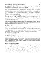
In F ig. 6, the complementary cumulative distribution function (ccdf )oftheperceived
throughput is shown when N
= 1, 2, 3, 5, 10, and 20 users are randomly placed in the coverage
area of both technologies: for a given value
T of throughput (reported in the abscissa), the
corresponding ccd f provides the probability that the throughput experienced by an user is
higher than
T.
For each value of N, 1000 random placements of the users were performed; the already
discussed MRRM strategies are compared:
• autonomous RAT switching;
• assisted RAT switching;
• parallel transmission.
With reference to Fig. 6(a), that refers to the case of a s ingle user, there is obviously
no difference adopting the autonomous RAT switching strategy or the assisted RAT switching
strategy. In the absence of other users the choice made by the two strategies is inevitably the
same: WiFi is used at low distance from the PoA, while WiMAX is preferred in the opposite
case.
The results reported in Fig. 6(a) also confirm that in the case of a single user the perceived
throughput can significantly increase thanks to the use of the parallel transmission strategy, as
discussed in Section 4.4. The significant improvement provided in this case by the parallel
transmission strategy is not surprising: in the considered case of a single user, in fact, both the
autonomous RAT switching strategy and the assisted RAT switching strategy leave one of the two
RATs definitely unused, which is an inauspicious condition.
This consideration suggests that the number of users in the scenario plays a relevant role in
the detection of the best MRRM strategy, thus the following investigations, whose outcomes
are reported in figures from 6(b) to 6(f), refer to scenarios with N
= 2, 3, 5, 10, and 20 users,
respectively. As can be observed, when more than one user is considered the dynamic RAT
switching always outperforms the no RAT switching and the advantage of using the parallel
transmission strategy becomes less clear.
Let us focus our attention, now, on Fig. 6(b), that refers to the case of N
= 2users
randomly placed within the scenario. When the parallel transmission strategy is adopted, the
100% of users perceive a throughput no lower than 7.9 Mb/s, whereas the autonomous RAT
switching strategy and the assisted RAT switching strategies provides to the 100% of users a
throughput no lower than 6.3 Mb/s. It follows that, at least in the case of N
= 2users,the
parallel transmission strategy outperforms the other strategies in terms of minimum guaranteed
throughput. Fig. 6(b) al so shows that with the parallel transmission strategy the probability
of perceiving a thro ughput higher than 9 Mb/s is reduced with respect to the case of the
assisted RAT switching strategy. This should not be deemed necessarily as a negative aspect:
142
Quality of Service and Resource Allocation in WiMAX
Multi Radio Resource Management over WiMAX-WiFi Heterogeneous Networks: Performance Investigation
7
15
0 5 10 15 20 25 30
0
0.1
0.2
0.3
0.4
0.5
0.6
0.7
0.8
0.9
1
Throughput of each UE [Mb/s]
ccdf
Autonomous RAT switching
Assisted RA T switching
Parallel transmission
(a) One user.
0 5 10 15
0
0.1
0.2
0.3
0.4
0.5
0.6
0.7
0.8
0.9
1
Throughput of each UE [Mb/s]
ccdf
Autonomous RAT switching
Assisted RAT switching
Parallel transmission
6.3 Mb/s
7.9 Mb/s
9 Mb/s
(b) Two users.
0 2 4 6 8 10
0
0.1
0.2
0.3
0.4
0.5
0.6
0.7
0.8
0.9
1
Throughput of each UE [Mb/s]
ccdf
Autonomous RAT switching
Assisted RAT switching
Parallel transmission
(c) Three users.
0 1 2 3 4 5 6
0
0.1
0.2
0.3
0.4
0.5
0.6
0.7
0.8
0.9
1
Throughput of each UE [Mb/s]
ccdf
Autonomous RAT switching
Assisted RAT switching
Parallel transmission
(d) Five users.
0 0.5 1 1.5 2 2.5 3
0
0.1
0.2
0.3
0.4
0.5
0.6
0.7
0.8
0.9
1
Throughput of each UE [Mb/s]
ccdf
Autonomous RAT switching
Assisted RAT switching
Parallel transmission
(e) Ten users.
0 0.5 1 1.5
0
0.1
0.2
0.3
0.4
0.5
0.6
0.7
0.8
0.9
1
Throughput of each UE [Mb/s]
ccdf
Autonomous RAT switching
Assisted RAT switching
Parallel transmission
(f) Twenty users.
Fig. 6. Ccdf of the throughput perceived by N users randomly placed in the scenario.
143
Multi Radio Resource Management
over WiMAX-WiFi Heterogeneous Networks: Performance Investigation
16 Will-be-set-by-IN-TECH
everything considered we can state, in fact, that the parallel transmission strategy is fairer
than the assisted RAT switching strategy (at least in the case of N = 2 users), since it penalizes
lucky UEs (those closer to the PoA) providing a benefit to unlucky users.
Increasing the number of users to N
= 3, 5, 10, and 20 (thus referring to Figs. 6(c), 6(d), 6(e),
and 6(f), respectively), the autonomous RAT switching strategy confirms its poor performance
with respect to both the other strategies, while the ccd f curve related to the assisted RAT
switching strategy moves rightwards with respect to the parallel transmission curve, thus
making the assisted RAT switching strategy preferable as the number of users increases.
Let us observe, however, that passing from N
= 10 to N = 20 users, the relative positions
of the ccd f curves related to the parallel transmission strategy and the assisted RAT switching
strategy do not change significantly and the gap between the two curves is not so noticeable.
It follows that in scenarios with a reasonable number of users the parallel transmission strategy
could still be a good (yet suboptimal) choice, since, differently from the assisted RAT switchin g
strategy, no signalling phase is needed.
6. Conclusions
In this chapter the integration of RATs with overlapped coverage has been investigated, with
particular reference to the case of a heterogeneous WiFi-WiMAX network.
Three different M RRM strategies (autonomous RAT switching, assisted RAT switching and
parallel transmission) have been discussed, aimed at effectively exploiting the joint pool of
radio resources. Their performance have been derived, either analytically or by means of
simulations, in order to assess the benefit provided to a “dual-mode” user. In the case of
the parallel transmission over two technologies a traffic distribution strategy has been also
proposed, in order to overcome critical interactions with the TCP protocol.
The main outcomes of our investigations can be summarized as follows:
•innocasetheautonomous RAT switching strategy is the best solution;
• in the case of a single user the parallel transmission strategy provides a total throughput as
high as the sum of throughputs of the single RATs;
•theparallel transmission strategy generates a disordering of upper layers packets at the
receiver side; this issue should be carefully considered when the parallel transmission
refers to a TCP connection;
• as the number of users increases the assisted RAT switching strategy outperforms the parallel
transmission strategy.
7. References
3GPP-TR-43.902 (2007). Technical specification group gsm/edge radio access network;
enhanced generic access networks (egan) study; v10.0.0; (release 10).
3GPP-TS-43.318 (2007). Technical specification group gsm/edge radio access network; generic
access network (gan); v10.1.0; stage 2 (release 10).
Akyildiz, I. F., Lee, W Y., Vuran, M. C. & Mohanty, S. (2006). Next generation/dynamic
spectrum access/cognitive radio wireless networks: a survey, Computer Networks
50(13): 2127 – 2159.
Andrisano, O., Bazzi, A., Diolaiti, M., Gambetti, C. & Pasolini, G. (2005). Umts and wlan
integration: architectural solution and performance, Personal, Indoor and Mobile Radio
144
Quality of Service and Resource Allocation in WiMAX
Multi Radio Resource Management over WiMAX-WiFi Heterogeneous Networks: Performance Investigation
8
17
Communications, 2005. PIMRC 2005. IEEE 16th International Symposium on,Vol.3,
pp. 1769 –1775 Vol. 3.
Batra, A., Balakrishnan, J. & Dabak, A. (2004). Multi-band OFDM: a new approach for UWB,
Circuits and Systems, 2004. ISCAS ’04. Proceedings of the 2004 International Symposium
on.
Bazzi, A. (2010). Wlan hot spots to increase umts capacity, Personal Indoor and Mobile Radio
Communications (PIMRC), 2010 IEEE 21st International Symposium on, pp. 2488 –2493.
Bazzi, A., Pasolini, G. & Andrisano, O. (2008). Multiradio resource manag ement: Parallel
transmission for higher throughput?, EURASIP Journal on Advances in Signal
Processing 2008. 9 pages.
Bazzi, A., Pasolini, G. & Gambetti, C. (2006). Shine: Simulation platform for heterogeneous
interworking networks, Communications, 2006. ICC ’06. IEEE International Conference
on, Vol. 12, pp. 5534 –5539.
Ben Ali, R. & Pierre, S. (2009). On the impact of soft vertical handoff on optimal voice
admission control in PCF-based WLANs loosely coupled to 3G networks, IEEE
Transactions on Wireless Communications 8: 1356 – 1365.
Bennett, J., Partridge, C. & Shectman, N. (1999). Packet reordering is not pathological network
behavior, Networking, IEEE/ACM Transactions on 7(6): 789 –798.
Chebrolu, K. & Rao, R. (2006). Bandwidth aggregation for real-time ap plications in
heterogeneous wireless networks, Mobile Computing, IEEE Transactions on 5(4): 388
– 403.
Cunningham, G., Perry, P. & Murphy, L. (2004). Soft, vertical handover of streamed video,
5th IEE International Conference on Mobile Communication Technologies, 2004. (3G 2004).,
IEE, London, UK, pp. 432 – 436.
Dimou, K., Agero, R., Bortnik, M., Karimi, R., Koudouridis, G., Kaminski, S., Lederer,
H. & Sachs, J. (2005). Generic link layer: a solution for multi-radio transmission
diversity in communication networks beyond 3G, Vehicular Technology Conference,
2005. VTC-2005-Fall. 2005 IEEE 62nd.
Floyd, S. & Henderson, T. (1999). The newreno modification to tcp’s fast recovery algorithm,
Request for Comments: 2582, pp. 1 –11.
Fodor, G., Furuskär, A. & Lundsjö, J. (2004). On access selection techniques in always
best connected networks, In Proc. ITC Specialist Seminar on Performance Evaluation of
Wireless and Mobile Systems.
Hsieh, H Y. & Sivakumar, R. (2005). A transport layer approach for achieving aggregate
bandwidths on multi-homed mobile hosts, Wireless Networks 11: 99–114.
Huang, H. & Cai, J. (2006). Adding network-lay er intelligence to mobile receivers for solving
spurious TCP timeout during vertical handoff., IEEE Network 20: 24 – 31.
IEEE-802.11 (2005). Iso/iec standard for information technology - telecommunications and
information exchange between systems - local and metropolitan area networks
- specific requirements part 11: Wireless lan medium access control (mac) and
physical layer (phy) specifications (includes ieee std 802.11, 1999 edition; ieee std
802.11a 1999; ieee std 802.11b 1999; ieee std 802.11b 1999/cor 1-2001; and ieee std
802.11d 2001), ISO/IEC 8802-11 IEEE Std 802.11 Second edition 2005-08-01 ISO/IEC
8802 11:2005(E) IEEE Std 802.11i-2003 Edition pp. 1 –721.
IEEE802.11a (1999). Supplement to ieee standard for information technology -
telecommunications and information exchange between systems - local and
metropolitan area networks - specific requirements. part 11: Wireless lan medium
145
Multi Radio Resource Management
over WiMAX-WiFi Heterogeneous Networks: Performance Investigation
18 Will-be-set-by-IN-TECH
access control (mac) and physical layer (phy) specifications: High-speed physical
layer in the 5 ghz band, IEEE Std 802.11a-1999 p. i.
IEEE802.11u (2011). Ieee standard for information technology-telecommunications and
information exchange between systems-local and metropolitan networks-specific
requirements-part ii: Wireless lan medium access control (mac) and physical layer
(phy) specifications: Amendment 9: Interworking with external networks, IEEE Std
802.11u p. i.
IEEE802.16e (2006). Ieee standard for local and metropolitan area networks part 16: Air
interface for fixed and mobile broadband wireless access systems amendment
2: Physical and medium access control layers for combined fixed and mobile
operation in licensed bands and corrigendum 1, IEEE Std 802.16e-2005 and IEEE Std
802.16-2004/Cor 1-2005 (Amendment and Corrigendum to IEEE Std 802. 16-2004) pp. 1
–822.
IEEE802.21 (2010).
URL: />Iyengar, J., Amer, P. & Stewart, R. (2006). Concurrent multipath transfer using
SCTP multihoming over independent end-to-end paths, Networking, IEEE/ACM
Transactions on 14(5): 951 –964.
Koudouridis, G., Karimi, H. & Dimou, K. (2005). Switched multi-radio transmission diversity
in future access networks, Vehicular Technology Conference, 2005. VTC-2005-Fall. 2005
IEEE 62nd.
Lim, W S., Kim, D W., Suh, Y J. & Won, J J. (2009). Implementation and performance study
of ieee 802.21 in integrated ieee 802.11/802.16e networks, Computer Communications
32(1): 134 – 143.
Luo, J., Mukerjee, R., Dillinger, M., Mohyeldin, E. & Schulz, E. (2003). Investigation of radio
resource scheduling in WLANs coupled with 3G cellular network, Communications
Magazine, IEEE 41(6): 108 – 115.
Mehta, M. & Vaidya, N. (1997). Delayed duplicate acknowledgments: A proposal to improve
performance of tcp on wireless links, Tech. Rep., Texas A&M University .
Naoe, H., Wetterwald, M. & Bonnet, C. (2007). IPv6 soft handover applied to network mobility
over heterogeneous access networks., IEEE 8th International Symposium on Personal,
Indoor and Mobile Radio Communications, 2007. (PIMRC 2007)., IEEE, Athens, Greece,
pp. 1–5.
Rutagemwa, H., Pack , S., Shen, X. & Mark, J. (2007). Robust cross-layer design of
wireless-profiled TCP mobile receiver for vertical handover., IEEE Transactions on
Vehicular Technology. 56: 3899 – 3911.
Sachs, J., Wiemann, H., Lundsjo, J. & Magnusson, P. (2004). Integration of multi-radio access in
a beyond 3g network, Personal, Indoor and Mobile Radio Communications, 2004. PIMRC
2004. 15th IEEE International Symposium on, Vol. 2, pp. 757 – 762 Vol.2.
Song, W., Zhuang, W. & Cheng, Y. (2007). Load balancing for cellular/wlan integrated
networks, IEEE Network 21: 27–33.
Tanenbaum, A. S. (1996). Computer Networks, Prentice Hall, Upper Saddle River, NJ.
Veronesi, R. (2005). Multiuser scheduling with multi radio access selection, Wireless
Communication Systems, 2005. 2nd International Symposium on, pp. 455 –459.
Wang, N C., Wang, Y Y. & Chang, S C. (2007). A fast ad aptive congestion control
scheme for improving TCP performance during soft vertical handoff., IEEE Wireless
Communications and Networking Conference, 2007. (WCNC 2007)., IEEE, Hong Kong,
pp. 3641–3646.
146
Quality of Service and Resource Allocation in WiMAX
0
A Cross-Layer Radio Resource Management in
WiMAX Systems
Sondes Khemiri Guy Pujolle
1
and Khaled Boussetta Nadjib Achir
2
1
LIP6, University Paris 6, Paris
2
L2TI, University Paris 13, Villetaneuse
1
France
1. Introduction
This chapter ad dresses the issue of a cross layer radio resource management in IEEE 802.16
metropolitan network and focuses specially on IEEE 802.16e-2005 WiMAX network with
Wireless MAN OFDMA physical layer. A wireless bandwidth allocation strategy for a mobile
WiMAX network is very important since it determines the maximum average number of users
accepted in the network and consequently the provider gain.
The purpose of the chapter is to give an overview of a cross-layer resource allocation
mechanisms and describes optimization problems with an aim to fulfill three objectives: (i)
to maximize the utilisation ratio of the wireless link, (ii) to guarantee that the system satisfies
the QoS constraints of application carried by subscribers and (iii) to take into account the radio
channel environment and the system specifications.
The chapter is organized as follows: Section 1 and 2 describe the most important concepts
defined by IEEE 802.16e-2005 standard in physical and MAC layer, Section 3 presents an
overview of QoS mechanisms described in the literature, Section 4 gives a guideline to
compute a physical slot capacity needed in resource allocation problems, the cross-layer
resource management problem formalization is detailed in section 5. Solutions are presented
in section 6. Finally, section 7 summarizes the chapter.
2. Mobile WiMAX overview
This section presents an overview of the most important concepts defined by IEEE
802.16e-2005 standard in physical and MAC layer, that are needed in order to define a system
capacity.
2.1 WiMAX PHY layer
We will give in this section details about PHY layer and we will focus specially on specified
concepts that must be taken into account in allocation bandwidth problem namely, the
specification of the PHY layer, the OFDMA multiplexing scheme and the permutation scheme
for sub-channelization from which we deduce the bandwidth unit allocated to accepted calls
in the system and the Adaptive Modulation and Coding scheme (AMC).
7
2 Will-be-set-by-IN-TECH
2.1.1 Generality
The IEEE 802.16 defines five PHY layers which can be used with a MAC layer to form a
broadband wireless system.
These PHY layers provide a large flexibility in terms of bandwidth channel, duplexing scheme
and channel condition. These layers are described as follows:
1. WirelessMAN SC: In this PHY layer single carriers are used to tr ansmit information for
frequencies beyond 11GHz in a Line of sight (LOS) condition.
2. WirelessMAN SCa: it also relies on a single carrier transmission scheme, but for
frequencies between 2 GHz and 11GHz.
3. WirelessMAN OFDM (Orthogonal Frequency Division Multiplexing): it is based on a Fast
Fourier Transform (FFT) with a size of 256 points. It is used for point multipoint link in a
non-LOS condition for frequencies between 2 GHz and 11GHz.
4. WirelessMAN OFDMA (OFDM Access): Also referred as mobile WiMAX , it is also based
on a FFT with a size of 2048 points. It is used in a non LOS condition for frequencies
between 2 GHz and 11GHz.
5. Finally a WirelessMAN SOFDMA (SOFDM Access): OFDMA PHY layer has been
extended in IEEE 802.16e to SOFDMA (scalable OFDMA) where the size is variable and
can take different values: 128, 512, 1024, and 2048.
In this chapter we will focus only on the WirelessMAN OFDMA PHY layer. As we saw in
previous paragraph many combination of configuration parameters like b and frequencies,
channel bandwidth and duplexing techniques are possible. To insure interoperability between
terminals and base stations the W iMAX Forum has defined a set of WiMAX system profiles.
The latter are basically a set of fixed configuration parameters.
2.1.2 OFDM, OFDMA and subchannelization
The WiMAX PHY layer has also the responsibility of resource allocation and framing over
the radio channel. In follows, we will define this physical resource. In fact, the mobile
WiMAX physical layer is based on Orthogonal Frequency Multiple Access (OFDMA), which is
a multi-users extension of Orthogonal Frequency-Division Multiplexing (OFDM) technique.
The latter principles consist of a simultaneous transmission of a bit stream over orthogonal
frequencies, also called OFDM sub-carriers. Precisely, the total bandwidth is divided into a
number of orthogonal sub-carriers. As described in mobile WiMAX (Jeffrey G. et al., 2007),
the OFDMA sharing capabilities are augmented in multi-users context thanks to the flexible
ability of the standard to divide the frequency/time resources between users. The minimum
time-frequency resource that can be allocated by a WiMAX system to a given link is called a
slot. Precisely, the basic unit of allocation in the time-frequency grid is named a slot. Broadly
speaking, a slot is an n x m rectangle, where n is a number of sub-carriers called sub-channel
in the frequency domain and m is a number of contiguous symbols in the time domain.
WiMAX defines several sub-channelization schemes. T he sub-channelization could be
adjacent i.e. sub-carriers are grouped in the same frequency r ange in each sub-channel or
distributed i.e. sub-carriers are pseudo-randomly distributed across the frequency spectrum.
So we can find:
• F ull usage sub-carriers (FUSC): Each slot is 48 sub-carriers by one OFDM symbol.
148
Quality of Service and Resource Allocation in WiMAX
A Cross-Layer Radio Resource Management in WiMAX Systems 3
• Down-link Partial Usage of Sub-Carrier (PUSC): Each slot is 24 sub-carriers by two OFDM
symbols.
• Up-link PUSC and TUSC Tile Usage of Sub-Carrier: Each slot is 16 sub-carriers by three
OFDM symbols.
• Band Adaptive Modulation and Coding (BAMC) : As we see in figure 1 each slot is 8, 16,
or 24 sub-carriers by 6, 3, or 2 OFDM symbols.
Fig. 1. BAMC slot format
In this chapter we will focus on the last permutation scheme i.e BAMC and we will explain
how to compute the slot capacity.
2.1.3 The Adaptive Modulation and Coding scheme (AMC)
In order to adapt the transmission to the time varying channel conditions that depends on the
radio link characteristics WiMAX presents the advantage of supporting the l ink adaptation
called Adaptive Modulation and Coding s cheme (AMC). It is an adaptive modification of the
combination of modulation, channel coding types and coding rate also known as burst profile
that takes place in the physical link depending on a new radio condition. The following table
1 shows examples of burst profiles in mobile WiMAX, among a total of 52 profiles defined
in IEEE802.16e-2005 (IEEE Std 802.16e-2005, 2005): In fact when a subscriber station tries to
Profile Modulation Coding scheme Rate
0 BPSK (CC)
1
2
1 QPSK (RS + CC/CC)
1
2
2 QPSK (RS + CC/CC)
3
4
3 16 QAM (RS + CC/CC)
1
2
6 64 QAM (RS + CC/CC)
3
4
Table 1. Burst profile examples: (CC)Convolutional Code,(RS) Reed-Solomon
enter to the system, the WiMAX network undergoes various steps of signalization. First, the
Down-link channel is scanned and synchronized. After the synchronization the SS obtains
information about PHY and MAC parameters corresponding to the DL and UL transmission
from control messages that follow the preamble of the DL frame. Based on this information
negotiations are established between the SS and the BS about basic capabilities like maximum
transmission power, FFT size, type of modulation, and sub-carrier permutation support.
In this negotiation the BS takes into account the time varying channel conditions by computing
the signal to noise ratio (SNR) and then decides which burst profile must be used for the SS.
149
A Cross-Layer Radio Resource Management in WiMAX Systems
4 Will-be-set-by-IN-TECH
In fact, using the channel quality feedback indicator, the downlink SNR is provided by the
mobile to the base station. For the uplink, the base station can estimate the channel quality,
based on the received signal quality.
Based on these informations on signal quality, different modulation schemes will be employed
in the same network in order to maximize throughput in a time-varying channel. Indeed,when
the d istance between the base station and the subscriber station increases the signal to
the noise ratio decreases due to the path loss. Consequantely, modulation must be used
depending on the station position starting from the lower efficiency modulation (for terminals
near the BS) to the higher efficiency modulation (for terminals far away from the BS).
2.2 WiMAX MAC layer and QoS overview
The primary task of the WiMAX MAC layer is to provide an interface between the higher
transport layers and the physical layer. The IEEE 802.16-2004 and IEEE 802.16e-2005 MAC
design includes a convergence sublayer that can interface with a variety of higher-layer
protocols, such as ATM,TDM Voice, Ethernet, IP, and any unknown future protocol.
Support for QoS is a fundamental part of the WiMAX MAC-layer design. QoS control is
achieved by using a connection-oriented MAC architecture, where all downlink and uplink
connections are controlled by the serving BS. Before any data transmission happens, the
BS and the MS establish a unidirectional logical link, called a connection, between the two
MAC-layer peers. Each connection is identified by a connection identifier (CID), which serves
as a temporary address for data transmissions over the particular link. WiMAX also defines a
concept of a service flow. A service flow is a unidirectional flow of packets with a particular
set of QoS parameters and is identified by a service flow identifier (SFID). The QoS parameters
could include traffic priority, maximum sustained traffic rate, maximum burst rate, minimum
tolerable rate, scheduling type, ARQ type, maximum delay, tolerated jitter, service data unit
type and size, bandwidth request mechanism to be used, transmission PDU formation rules,
and so on. Service flows may be provisioned through a network management system or
created dynamically through defined signaling mechanisms in the standard. The base station
is responsible for issuing the SFID and mapping it to unique CIDs. In the following, we will
present the service classes of mobile WiMAX characterized by these SFIDs.
2.2.1 WiMAX service classes
Mobile WiMAX is emerging as o ne of the m ost promising 4G technology. It has be en
developed keeping in view the stringent QoS requirements of multimedia applications.
Indeed, the IEEE 802.16e 2005 standard defines five QoS scheduling services that should be
treated appropriately by the base station MAC scheduler for data transport over a connection:
1. Unsolicited Grant Service (UGS) is dedicated to real-time s ervices that generate CBR or
CBR-like flows. A typical application would be Voice over IP, without silence suppression.
2. Real-Time Polling Service (rtPS) is designed to support real-time services that generate
delay sensitive VBR flows, such as MPEG video or VoIP (with silence suppression).
3. Non-Real-Time Polling Service (nrtPS) is designed to support delay-tolerant data delivery
with variable size packets, such as high bandwidth FTP.
4. Best Effort (BE) service is proposed to be used for all applications that do not require any
QoS guarantees.
150
Quality of Service and Resource Allocation in WiMAX
A Cross-Layer Radio Resource Management in WiMAX Systems 5
5. Extended Real-Time Polling Service (ErtPS) is expected to provide VoIP services with Voice
Activation Detection (VAD).
Note that the standard defines 4 service classes for Fixed W iMAX: UGS, rtPS, nrtPS and BE.
In order to guarantee the QoS for these different service classes Call Admission Control (CAC)
and resource reservation strategies are needed by the IEE 802.16e system.
2.2.2 QoS mechanisms in WiMAX
To satisfy the constraints of service classes, several QoS mechanisms should be used. Figure 2
shows the steps to be followed by the BS and SSs or MSSs to ensure a robust QoS management.
To manage the QoS, we distinguish between the management in the UL and DL. For UL, at the
Fig. 2. QoS mechanisms
SS, the first step is the traffic classification that classifies the flow into several classes, followed
by the bandwidth request step, which depends on service flow characteristics. Then the base
station scheduler can place the packets in BS files, depending on the constraints of their
services, which are indicated in the CID (Connexion IDentifier). The band width allocation
is based on requests that are sent by the SSs. The BS generates UL MAP messages to indicate
whether it accepts or n ot to allocate the bandwidth required by the SSs. Then, the SS or MSS
processes the UL MAP messages and sends the data according to these messages.
For the downlink, the base station gets the traffic, classifies it following the CID and generates
the DL MAP messages in which it outlines the DCD messages that determine the burst
profiles.
The following section will describe each step. It should be noted that the standard does not
define in detail each mechanism. But i t is necessary to understand some methods that are
used to satisfy the QoS for each mechanism.
1. The classification T h e classifier matches the MSDU to a particular connection
characterized by an CID in order to transmit it. This is called CID mapping that
corresponds to the mapping of fields in the MSDU (for example mapping the couple
composed of the destination IP address and the TOS field) in the CID and the SFID.
The mapping process associates an MSDU to a connection and creates an association
between this connection and service flow characteristics. It is used to facilitate the
transmission of MSDU within the QoS constraints.
Thus, the packets p rocessed by the classifier are classed into the diffrent WiMAX
service classes and have the correspondant CID. The standard didn’t define precisely the
classification mechanism and many works in the literature have been developed in order to
define the mapping in QoS cross layer framework. Once classified the connection requests
are admitted or r ejected following the call admission control mechanism decision.
151
A Cross-Layer Radio Resource Management in WiMAX Systems
6 Will-be-set-by-IN-TECH
2. Call admission control (CAC) and Bandwidth Allocation As in cellular networks, the
IEEE 802.16 Base Station MAC layer is in charge to regulate and control bandwidth
allocation. Therefore, incorporating a Call Admission Control (CAC) agent becomes the
primary method to allocate network resources in such a way that the QoS user constraints
could be satisfied. Before any connection establishment, each SS informs the BS about its
QoS requirements. And the BS CAC agent have the responsability to determine whether
a connection request can be accepted or should be rejected. The rejection of request
happens if its QoS requirements cannot be satisfied or if its acceptance may violate the
QoS guarantee of ongoing calls.
To well manage the operation of this step, the WiMAX standard provides tools and
mechanisms for bandwidth allocation and request that is described briefly as follows:
(a) Bandwidth request At the entrance to the network, each SS or MSS is allocated up to
3 dedicated CID identifiers. These CIDs are used to send and receive control messages.
Among these messages one can distinguish Up-link Channel Descriptor, Downlink
Channel Descriptor, UL-MAP and DL-MAP messages, plus messages concerning the
bandwidth request. The latter can be sent by the SS following one of these modes:
• Implicit Requests: This mode corresponds to UGS traffic which requires a fixed bit
rate and does not require any negotiation.
• Bandwidth request message: This message type uses headers named BW request.It
reaches a length of 32 KB per request by CID.
• Piggybacked request: is integrated into useful messages and is used for all service
classes, except for UGS.
•RequestbythebitPoll-Me: is used by the SS to request bandwidth for non-UGS
services.
(b) Bandwidth Allocation modes
There are two modes of bandwidth allocation:
• The Grant Per Subscriber Station (GPSS): In this mode, the BS guarantes the
aggregated bandwidth per SS. Then the SS allocates the required bandwidth for
each connection that it carries. This allocation must be performed by a scheduling
algorithm. This method has the advantage of having multiple users by SS and
therefore requires less overhead. However, it is more complex to implement because
it requires sophisticated SSs that support a hierarchical distributed scheduler.
• The Grant Per Connection (GPC): In this type of allocation the BS guarantes
the bandwidth per connection, which is identified thanks to the individual CID
(Connection IDentifier). This method has the advantage of being simpler to design
than the GPSS mode but is adapted for a small number of users per SS and provides
more overhead than the first mode.
Thus, based o n SS and MSS requests the base station can satisfy the other QoS
application constraints by employing different allocation bandwidth strategies and call
admission control policies. Recall that the latters have not been defined in the standard.
3. Scheduling In WiMAX, the scheduling mechanism consists of determinating the
information element (IE) sent in the UL MAP m essage that indicates the amount of the
allocated bandwidth, the allocated slots etc A simplified diagram of the scheduler in the
standard IEEE 802.16 is illustrated in the following figure:
The scheduler in the WiMAX has been defined only for UGS traffic. Precisely for this class,
the BS determines the IEs UL MAP message by allocating a fixed number of time slots in
152
Quality of Service and Resource Allocation in WiMAX
A Cross-Layer Radio Resource Management in WiMAX Systems 7
Fig. 3. Scheduler in IEEE 802.16 standard
each frame interval. The BS must take into account the state of queues associated to traffic
and all queues among the SS, corresponding to UL traffic. For the remaining traffic classes
the standard does not specify a particular scheduling algorithm, and left the choice to the
operator to implement one of the algorithm that was described in the literature (Jianfeng
C. et al., 2005) (Wongthavarawat K. et al, 2003).
4. The mapping
This is the final step before sending user data in the radio channel. The idea is to assign
sub-carriers in the most efficient possible way to scheduled MPDUs in order to satisfy
QoS constraints of each connection. The mapping mechanism is left to the choice of the
provider.
3. State of the art
3.1 Bandwidth sharing strategies: background
To maintain a quality of service required by the constraining and restricting services, there
are different strategies of bandwidth allocation and admission control. Many bandwidth
allocation policies have been developed in order to give for different classes a certain amount
of resource. Among the classical strategies, one can citeComplete Sharing (CS), Upper Limit
(UL), Complete Partitioning (CP), Guaranteed Minimum (GM) and Trunk Reservation (TR)
policies. These policies are illustrated in figure 4 and will be introduced in the following
sections. To this end, and in a seek of simplicity of the presentation, we will suppose in these
sections that system defines only two service classes 1 and 2 (instead of the 5 classes defined
in Mobile WiMAX). Moreover, we will also suppose that if a system accepts a call of class
i
∈{1, 2} it will allocate to this call a fixed amount of bandwidth denoted by d
i
. Finally, let n
i
denotes the number of class i ∈{1, 2} calls in the system.
Fig. 4. Heuristic CAC policies
3.1.1 Complete Sharing (CS)
In this strategy, the bandwidth is fully shared among the different service classes. That is all
classes are in competition. In other words, if we consider an offered capacity system equal to
C and 2 types of service class (class 1 and 2). If class 1 (i.e. aggreagted calls) uses I units then
153
A Cross-Layer Radio Resource Management in WiMAX Systems
8 Will-be-set-by-IN-TECH
the remained bandwidth C − I could be allocated either to class 1 or to class 2. Formally, a call
of class i
∈{1, 2} is accepted if and only if:
d
i
+
2
∑
k=1
n
k
d
k
≤ C (1)
3.1.2 Upper Limit (UL)
This policy is very similar to CS except that it aims to eliminate the case where one class can
dominate the use of the resource, through the use of thresholds-based bandwidth occupation
strategy. Precisely, thresholds t
1
and t
2
are associated to class1 and class 2, respectively. These
thresholds represent the maximum numbers of bandwdith units that each class can occupy at
agiventime.So,acallofclassi
∈{1, 2} is accepted if and only if:
(1 + n
i
)d
i
≤ t
i
and
2
∑
k=1
n
k
d
k
≤ C (2)
Note that this relation is not excluded :
2
∑
k=1
t
k
> C
3.1.3 Complete Partitioning (CP)
This policy allocates a set of resources for every service class. These resources can only be used
by that class. To this end the bandwidth is divided into partitions. Each partition is reserved
to an associated service class. In this figure the capacity is divided into 2 partitions denoted
by C
1
for class 1 and C
2
for class 2. Then, a call of class i ∈{1, 2} is accepted if and only if:
(1 + n
i
)d
i
≤ C
i
(3)
Note that contrarily to the UL strategy the following relation must always be verified:
2
∑
k=1
C
k
= C
3.1.4 Guaranteed Minimum (GM)
As illustrated in figure 4 the resource is divided into different partition. The policy gives each
classes their associated partition of bandwidth, which we note M
1
for class 1 and M
2
for class
2. If this partition is fully occupied, each class can then use the remaining resource partition
that is shared by all other classes. This is clearly an h ybrid strategy between CP and CS.
Formally, the CAC rule to follow in order to accept a call of class i
∈{1, 2} is:
2
∑
k=1
max(d
k
(n
k
+ 1
i
(k)), M
k
) ≤ C, wh ere 1
i
(k)=1 if k = i,0otherwise (4)
154
Quality of Service and Resource Allocation in WiMAX
A Cross-Layer Radio Resource Management in WiMAX Systems 9
Note that the following relation must always be verified:
2
∑
k=1
M
k
≤ C.
3.1.5 Trunk Reservation (TR)
As illustrated in figure 4, there are not dedicated partitions per classes in this policy. In fact,
class i
∈
{
1, 2
}
may use resources in a system as long as the amount of remaining resources is
equal to a certain threshold r
i
∈
{
1, 2
}
bandwidth units. Thus each service class will protected
thank to thresholds, which will avoid that any class occupies the totality of resource units. So
acallofclassi
∈{1, 2} is accepted if and only if:
d
i
+
2
∑
k=1
n
k
d
k
≤ C −r
i
(5)
This rule guarantees that after applying this CAC policy and accepting the class i the
remaining bandwidth is equal to r
i
. Several comparison have been made between these
policies and with optimal solution. One important challenge is to explain the method that
thresholds imposed by GM, UL and CP strategies are computed or determined which is
explained in (Khemiri S. et al., 2007).
So the main challenge is to setup these policy in an optimized way. This is could be done
by choosing the optimal partition sizes or reservation thresholds in order to 1) guarantee the
QoS constraints of the application provided by the system and in the other words to satisfy
subscribers and 2) to provide a good system performance which satisfies the provider.
3.2 Scheduling and mapping in the literature
Fig. 5. Scheduler classification
In literature few studies have focused on both the scheduling and the selection of MPDUs and
choice of OFDMA slots to be allocated (called mapping) to send the data in the frame.
Regarding scheduling, we can distinguish, as shown in Figure 5, two types of schedulers:
a) the non-opportunistic schedulers are tho se who do not take into account the state of the
channel we cite the best known, the RRs that ensure fairness and WRRs based on fixed weights
and b) the opportunistic schedulers are those that take into account the channel state (Ball et
al., 2005)(Rath H.K. et al., 2006)(Mukul, R et al.)(Qingwen Liu and Xin Wang and Giannakis,
155
A Cross-Layer Radio Resource Management in WiMAX Systems
10 Will-be-set-by-IN-TECH
G.B. et al.)(Mohammud Z. et al., 2010) an example is the MAXSNR which first selects the MSSs
that have the maximum SIR. In (Ball et al., 2005), the authors present an algorithm called TRS
that removes from queues MSSs with the SNR that is below a certain threshold. Further works
(Rath H.K. et al., 2006) (Laias E. et al ., 2008) improve conventional schedulers like DRR to
make opportunistic one and this by introducing the SNRs threshold as a criterion for selecting
MSSs to serve. Others are based on the prediction of the packets arrival like in (Mukul, R et
al.).
Regarding the mapping, in (Einhaus, M. et al 2006), the authors propose an al gorithm that
uses a combined dynamic selection of sub-channels and their modulation with a power
transmission allocation in an OFDMA packets but this proposal does not take into account
the constraints of QoS packets. ( Einhaus, M. et al) made a performance comparison
between multiple resource allocation strategies based on fairness of transmission capacity in a
multi-user scenario of a mobile WiMAX network that supports an OFDMA access technology.
These compared policies are the MAXSNR, the maximum waiting time and the Round Robin
strategies. The performance metrics analyzed are the delay and the rate. The evaluation
was conducted using a WiMAX simulator based on OFDMA mechanism developed in NS2
simulator. The results presented indicate the significant impact of these policies on the tradeoff
between rate and delay. Indeed, this work shows that a strategy based on taking into account
to the radio channel conditions gives a better performance in term of capacity utilization than
that of the delay. Thus the slot allocation strategies aiming to minimize the delay has resulted
in reducing the efficiency of resource use. However, this work does not address the specifics in
terms of QoS traffic and didn’t provide any service differentiation between classes UGS, rtPS,
and nrtPS Ertps. This work was improved in (Khemiri S. et al., 2010) by applying this strategy
to a mobile WiMAX network: authors compared it to MAXSNR well known as a conventional
mapping techniques. The results showed an improvement of a channel utilization.
In ( Akaiwa, Y. et al 1993) and (katzela I. et al, 1996) Channel segregation performance has
been examined by applying it to FDMA systems. This paper discusses its application to
the multi-carrier TDMA system. Spectrum e fficiency of the TDMA/FDMA cellular system
deteriorates due to the problem of inaccessible channel: a call can be blocked in a cell even
when there are idle channels because of the restriction on simultaneous use of different carrier
frequencies in the cell. This solution shows that channel segregation can resolve this problem
with a small modification of its algorithm. The performance of the system with channel
segregation on the call blocking probability versus traffic density is analyzed with computer
simulation experiments. The effect of losing the TDMA frame synchronization between cells
on the performance is also discussed.
In (Wong et al., 2004) Orthogonal Frequency Division Multiple Access (OFDMA) base stations
allow multiple users to transmit simultaneously on different subcarriers during the same
symbol period. This paper considers base station allocation of subcarriers and power to each
user to maximize the sum of user data r ates, subject to constraints on total power, bit error
rate, and proportionality among user data rates.
These works did not consider the double problem of MPDUs selection for transmission and
the channel assignment technique.
4. Slot capacity
As we seen before, the PHY layer provides different parameter stettings which leads to
interoperability problems. This is why WiMAX forum creates the WiMAX profiles which
156
Quality of Service and Resource Allocation in WiMAX
A Cross-Layer Radio Resource Management in WiMAX Systems 11
describes a set of parameters of an operational WiMAX system. These sets of parameters
concerns: The System Bandwidth, the system frequency and the duplexing scheme. This
section gives a computational method of slot capacity based on two WiMAX system profiles:
1) The Fixed WiMAX system profile and 2) The mobile WiMAX system profile.
This slot capacity, computed in term of bits, depends on permutation type and parameters
which depends on the radio mobile environment like burst profile and defined by the SINR
(Chahed T. et al, 2009) (Chahed T. et al, 2009). To compute this capacity its is needed to know
system parameters, so we distinguish:
1. The OFDM slot capacity compute in case of Fixed WiMAX profile system.
2. The OFDMA slot capacity compute in case of Mobile WiMAX profile system.
The following table describes the parameters of each system profile:
Parameters definition Fixed Mobile
B System Bandwidth 3.5 MHz 10 MHZ
L
FFT
Subcarrier number or FFT size 256 1024
L
d
Data subcarrier number 192 720
G Guard time 12.5% 12.5%
n
f
Oversampling rate 8/7 28/25
(DL : UL) Duplexing rate 3:1 3:1
( c, M) Modulation and coding scheme depending depending
c = coding r ate on channel on channel
M = Constel l atio n o f the modul ation
TTG and RTG transition Gap between UL and DL 188μs 134.29μs
T Frame length ms 5ms 5ms
N Number of user N N
Perm Permutation mode - BAMC 1X6
Table 2. Mobile and fixed WiMAX system parameters
4.1 Fixed WiMAX case
Lets consider an SS n and one subcarrier f, we can determine the corresponding SINR
n, f
and then the modulation and coding scheme (c
n, f
, M
n, f
). One subcarrier can transmit the
following number of bits (Wong et al., 2004) (Chung S. et al, 2000):
b
n, f
= c
n, f
log
2
M
n, f
(6)
An OFDM slot, denoted by s,iscomposedbyL
d
data subcarriers. The channel state of a user
n described by SINR
n,s
can be deduced by computing the mean SINR of all data subcarriers.
Once this SINR is determined we can deduce the MCS
(c
n
, M
n
) and we can compute the SINR
as follows:
SINR
n,s
=
1
L
d
L
d
∑
f =1
SINR
n, f
(7)
157
A Cross-Layer Radio Resource Management in WiMAX Systems
12 Will-be-set-by-IN-TECH
So the number of bits that can transmit the minimum time-frequency resource or a the OFDM
slot is defined as follows:
b
n
= c
n
log
2
(M
n
)L
d
(8)
Where
(1+G)L
FFT
n
f
B
corresponds to t ime duration of the OFDM symbol of L
FFT
length, s o the
rate in bps provided by an OFDM frame for a modulation and coding scheme
(c, M) is given
by:
C
= c log
2
(M)L
d
n
f
B
(L
FFT
(1 + G))
(9)
In addition, the total number of OFDM symbols per frame is computed as follows:
nb
s
= T
n
f
B
(1 + G)L
FFT
(10)
We deduce the number of symbols dedicated to the UL noted nb
UL
and the DL noted nb
DL
using the ratio (DL : UL):
nb
DL
=
D
D + U
nb
s
(11)
nb
UL
=
U
D + U
nb
s
(12)
The DL throughput is given by the following formula:
C
DL
=
CT
use f ul
1
T
nb
s
nb
DL
(13)
where T
use f ul
= T − (TTG + RTG) is the usable size of the frame by removing periods
reserved for the UL and DL transmission gap and
1
T
is the number of frames sent per second.
The total number of OFDM slots in a mobile WiMAX frame corresponds to S
×T where S = L
d
is the number of data subcarriers and T
s
= nb
s
is the number of OFDM symbol in the frame,
we obtain a frame with the format
((S = 192) ×(T
s
= 69)) OFDM slots.
4.2 Mobile WiMAX case
In mobile WiMAX, the slot format depends on the permutation scheme supported by the
system. In the rest of this chapter, we chose to take an interest in the permutation BAMC 1
×6.
This choice is not limiting, but for reasons of clarity and simplification of the presentation.
Considering the permutation BAMC 1
×6, the format of the OFDMA slot is 8 data subcarriers
of 6 OFDM symbols. The total number of OFDMA slots in a mobile WiMAX frame
corresponds to S
× T
s
where S =
L
d
8
and T
s
is the number of OFDM symbol in the frame
which is equal to T
s
=
nb
s
6
. Sowegetaframewhosesizeis((S = 90) × (T
s
= 6)) OFDMA
slots.
To determine the capacity of this slot s
∈ [1, S], it suffices to determine the burst profile
(c
n,s
, M
n,s
) of OFDMA slot s for user n. Todothis,simplydeterminetheSINR
n,s
corresponding to:
SINR
n,s
=
1
48
8
∑
f =1
6
∑
t∈1
SINR
n, f
(t) (14)
158
Quality of Service and Resource Allocation in WiMAX
A Cross-Layer Radio Resource Management in WiMAX Systems 13
Thus the number of bits provided by the OFDMA slot s is given by the following equation:
b
n,s
= 6 ∗8 c
n,s
log
2
(M
n,s
) (15)
Finally, using the parameter presented in table 2 and the equations above we obtain the
following table. It should be noted that the flow rates presented are calculated for the
modulation and coding scheme
(64 −QAM,
3
4
)
Parameters definition Fixed Mobile
(SxT
s
) Frame size (Total slot number) ( 192 ×69) (90 × 6)
C
DL
DL frame rate (Mbps) 8.51117 23.0905
C
UL
UL frame rate (Mbps) 2.83706 7.69682
C Total frame rate (Mbps) 11.348 30.787
b
n,s
Number of bit per slot (bits) 869 219
Table 3. Mobile and Fixed WiMAX slot capacity
In the rest of this chapter we focus on the slot allocation problem combined with scheduling
mechanism in mobile WiMAX OFDMA system which consists of how to assign PHY resource
to a user in order to satisfy a QoS request in MAC layer.
5. Case study: System description and problem statement
5.1 System description
In this case study let’s consider a WiMAX cell based on IEEE 802.16e 2005 technology
supporting Wireless MAN OFDMA physical layer. The system offers a quadruple-play service
to multiple mobile subscribers (MSS). These subscriber stations can have access anytime
and anywhere to various application types like file downloading, video streaming, emails
and VoIP. In this model let’s suppose a typical downlink WiMAX OFDMA system and we
consider that the system parameters corresponds to those of a mobile WiMAX profile, which
is characterized by the second column of the table 3.
Recall that the minimum time-frequency resource that can be allocated by a WiMAX system
to a given link is called a slot. Each slot consists of one sub-channel over one, two, or three
OFDM symbols, depending on the p a rticular sub-channelization scheme used. So a slot is
an n x m rectangle, where n is a number of sub-channel in the frequency domain and m is
a number of symbols in the time domain. The standard supports multiple subchannelization
schemes (PUSC, BAMC, FUSC, TUSC, etc.), which define how an OFDMA slot is mapped over
subcarriers. As we see in figure 6, the system frame is a matrix whose size is
((S = 90) ∗(T
s
=
6)) OFDMA slots, where S is the number of subchannels and T
s
is the number of OFDMA
symbols. So we can allocate up to 90
∗ 6 = 540 OFDMA slots to a user n. Only the DL case
will be studied. In order to model this system the physical and MAC layer characteristics will
be presented in following.
5.1.1 QoS constraints
In order to guarantee the quality of service required by these applications, the service provider
has to distinguish five service classes. Namely: UGS for VoIP, rtPS for video streaming, nrtPS
for file downloading and ErtPS for voice without silence suppression. As BE for emails is not
159
A Cross-Layer Radio Resource Management in WiMAX Systems
14 Will-be-set-by-IN-TECH
Fig. 6. OFDMA frame
constringent in term of QoS it will not be considered here. For notation simplicity, we will
refertoUGS,rtPS,nrtPSandErtPSasaclass1,2,3and4,respectively.LetU
= {1, 2, 3, 4}.To
satisfy application QoS constraints provided by the system, we assume that there is a classifier
implemented in the BS that associates each traffic users to a class i
∈ U and we also suppose
that there is a call admission control mechanism that ensures that the newly admitted calls do
not degrade the QoS of the ongoing calls, and there is enough available system resources for
the accepted call and if not the call is rejected. We suppose that to satisfy the QoS of each user
n supporting a traffic class i,itsufficestohave:
C
n
∈
[
s
i
, s
i
]
, ∀i ∈ U (16)
Where s
i
and s
i
, are respectively the minimum and maximum class i data rate. Since we
consider a mobile radio environment this system capacity vary with channel condition. This
is why a scheduling mechanism must be used in order to select which MPDUs must be
transmitted in addition to a physical resource assignment strategy in order to select the best
slot (physical resource) that satisfies the QoS constraints of the selected MPDUs.
5.1.2 Cell division for AMC
In order to adapt the transmission to the time varying channel conditions that depend on the
radio link characteristics WiMAX presents the advantage of supporting the l ink adaptation
called adaptive modulation coding (AMC). AMC consist of an adaptive modification of the
combination of modulation, channel coding types and coding rate also known as burst profile,
that takes place in the physical link depending on a new radio condition.
The following table 4 shows examples of burst profiles in mobile WiMAX there are 52 in
IEEE802.16e-2005 (Jeffrey G. et al., 2007)(IEEE Std 802.16e-2005, 2005):
160
Quality of Service and Resource Allocation in WiMAX
A Cross-Layer Radio Resource Management in WiMAX Systems 15
Profile Modulation L Coding scheme Rate
3 16 QAM (RS + CC/CC)
1
2
5 64 QAM (RS + CC/CC)
1
2
6 64 QAM (RS + CC/CC)
3
4
Table 4. Burst profiles: (RS) Reed Solomon, (CC) Convolutional Code
We will demonstrate in this section that we can divide the WiMAX cell into several areas
where each of them corresponds to one modulation scheme.
Lets consider our system as a WiMAX base station with a total bandwidth B operating at a
frequency f . The BS and SS antenna height in meters is respectively given by h
BS
and h
SS
.The
SS has a transmission power P
SS
. If we model our system in presence of path loss defined by
the COST -231 Hata radio propagation model (Jeffrey G. et al., 2007) (Roshni S. et al., 2007), we
can deduce a variation of the SNR while varying the distance d between SSs and BS (Chadi
T. et al., 2007) (Chadi T. et al ., 2007)(Chadi T. et al., 2007). This model is chosen because it
is recommended by the WiMAX Forum for mobility applications in urban areas which is the
case of our system.
In order to know the variation of the SNR with distance, the path loss for the urban system
environment is needed. According to the COST-231 Hata model, the pathloss is given by:
P
loss
[
dB
]
=
46.3 + 33.9log
10
(
f
)
−
13.82log
10
(
h
BS
)
+
(
44.9 −6.55log
10
(
h
BS
)
)
log
10
(
d
)
−
F
a
(
h
SS
)
+
C
F
(17)
Where P
loss
is the path loss, and F
a
(
h
SS
)
is the station antenna correction factor, C
F
is a
correction factor.
F
a
(
h
SS
)
=(
1.11log
10
(
f
)
−
0.7)h
SS
−(1.56log
10
(
f
)
−
0.8) (18)
For illustration lets consider an example of a WiMAX system with total bandwidth B
=
20MHz, operating at a frequency f = 2Ghz,withanSStransmissionpowerP
SS
= 10Watt =
10dBm, h
BS
= 30m, h
SS
= 1m.d = 0to20Km,C
F
= 3dB. The path loss is defined as:
P
loss
[
dB
]
=
41.17 + 35.26log
10
(
d
)
(19)
By considering the following link budget :
SNR
= P
SS
−
[
P
loss
+ N
]
(20)
Where N is the thermal noise equal to : N
[
dBm
]
=
10log
(
τTB
)
here τ = 1.38 ·10
−23
W/KHz
is the Boltzmann constant and T is the temperature in Kelvin
(T = 290) as defined in (Chadi
T. et al., 2007) N
[
dBm
]
= −
100.97dBm . we can deduce the SNR as follows:
SNR
= P
SS
+ 59.8 −35.26log
10
(
d
)
(21)
Using Matlab tool the variation of the SNR while varying the distance between SSs and
BSfrom0to20Kmisgivenbythefigure7Thisfigureshowsthatwecandistinguish
areas corresponding to the modulation region. We assume that our system supports only
161
A Cross-Layer Radio Resource Management in WiMAX Systems
16 Will-be-set-by-IN-TECH
Fig. 7. SNR variation versus distance BS-SS
3 modulation schemes, so following SNR thresholds described in table 4 we obtain three
modulation regions.
We assume that the cell’s bandwidth is totally partitioned, so that each partition is adapted
to a specific modulation scheme. According to the adaptive modulation and coding scheme,
we can divide this cell into 3 uniform areas in which we suppose that only one modulation
scheme is used. As figure 8 shows we choose 3 modulation and coding schemes as following:
1.
(
1
2
,16QAM) corresponds to the SNR interval I
1
=[0, 11.2[ dB.
2.
(
1
2
,64QAM) corresponds to the SNR interval I
2
=[11.2, 22.7] dB.
3.
(
3
4
,64QAM) corresponds to the SNR interval I
3
=]22.7, +∞[ dB.
Note that the
(
3
4
,64QAM) modulation (burst profile number 6) is used i n the nearest area
of the BS, then
(
1
2
,64QAM) modulation (burst profile number 5) in the second area, finally
(
1
2
,16QAM) (burst profile number 3) is employed in the third area.
Fig. 8. The system partition areas
Thus at the BS transmitter, the station must select for each user n
∈ [1, N] the MCS for each
selected slot s
∈ [1, S] using the signal to noise level SNR
n,s
.
In figure 8, we designed three zones illustrated by three concentric perfect circles
corresponding to the three types of modulation. It is just an example, because this obviously
162
Quality of Service and Resource Allocation in WiMAX
A Cross-Layer Radio Resource Management in WiMAX Systems 17
does not square with re ality since the channel undergoes disturbances other than the path
Loss that vary the channel between two stations even they are at the same distance from the
BS.
5.1.3 Mobility
In order to be close to a realistic WiMAX network, we take into account some assumptions.
We assume that N users are MSSs whose trajectory is a perfect concentric circle with radius
n
∈ [1, N] km. The velocity of the MSS n corresponds to V
n
= n ∗ V wherenistheuser
index and V is a velocity expressed by m/s. Each signal will be transmitted through a slowly
time-varying, frequency-selective Rayleigh channel with a bandwidth B. Each OFDMA slot s
allocated to a user n will be sent with a power denoted by p
n,s
.Wewilldiscussherethechoice
of this power.
In this case study, let’s consider that we allocate a fixed power p
k,s
=
P
S
for each subcarrier
since we didn’t focus on a power allocation problem. We assume that each user experiences
an independent fading and the channe l gain of user k in subcarrier s is denoted as g
k,s
We
can easily deduce that the n
th
user’s received signal-to-noise ratio (SNR) for the slot s which
corresponds to the average signal to noise ratios of all sub-carriers that form this slot, is written
as follows:
SNR
n,s
= p
n,s
g
2
n,s
σ
2
(22)
Where, σ
2
= N
0
B
L
FFT
and N
0
is power spectrum density of the Additive white Gaussian noise
(AWGN). The slowly time-varying assumption is crucial since it is also assumed that each user
is able to estimate the channel perfectly and these estimates are made known to the transmitter
via a dedicated feedback channel. Specifically, the SNR will be sent periodically (once per
frame) in control messages. Then they are used as input to the resource allocation algorithms.
We suppose that the channel condition didn’t change during the frame duration, i.e 5 ms.
5.2 Parameters and problem statement
As we consider a mobile WiMAX system supporting Adaptive Modulation and Coding we
can deduce from (Wong et al., 2004) and (Chung S. et al, 2000) the OFDMA slot capacity
denoted by b
n,s
corresponding to the number of bits that a given subcarrier s can transmit if
we know channel condition for a given user n, so we have:
b
n,s
= 48c
n,s
log
2
(M
n,s
) (23)
Where
(c
n,s
, M
n,s
) is the modulation and coding scheme of a slot s allocated to the MSS
n defined as follows:
(c
n,s
, M
n,s
)=(
1
2
,16QAM) if SNR
n,s
∈ I
1
, (c
n,s
, M
n,s
)=(
1
2
,64QAM) if
SNR
n,s
∈ I
2
and (c
n,s
, M
n,s
)=(
3
4
,64QAM) if SNR
n,s
∈ I
3
. As we see in 6 the OFDMA frame is
a matrix with dimension S
× T
S
. Let’s have an allocation matrix of a n
th
user denoted by A
n
,
this matrix is expressed as following:
A
n
=
a
n
s,t
(
s,t
)
∈
{
1,S
}
×
{
1,T
s
}
(24)
Where, a
n
s,t
= 1
{
1
(s,t)
=n
}
,ie,a
n
s,t
= 1 if and only if 1
(
s,t
)
(i, j)=n , 0 otherwise. By using
equations 23 and 24, we can deduce the total capacity B
n
which corresponds to the total bit
163
A Cross-Layer Radio Resource Management in WiMAX Systems
18 Will-be-set-by-IN-TECH
number provided to the user n after a slot allocation following the allocation matrix A
n
:
B
n
=
S
∑
s=1
T
s
∑
t=1
a
n
s,t
b
n,s
(25)
The total system capacity if the call admission controll mechanism accept N MSSs is:
C
=
N
∑
n=1
C
n
=
n
f
B
(1 + G)L
FFT
N
∑
n=1
S
∑
s=1
T
s
∑
t=1
a
n
s,t
c
n,s
log
2
(M
n,s
) (26)
It is clear that the choice of the matrix allocation is crucial for the optimal use of resources. The
aim of this case study is to present an efficient cross-layer resource assignment strategy that
takes into account two aspects: 1
)the varying channel condition and 2) the QoS constraints of
user’s MPDUs scheduled to be transmitted into the physical frame.
Problems related to resource allocation and power assignment aim to solve the following
mutli-constraints optimization problem (Wong et al., 2004) (Cheong et al., 1999):
Problem 1 Slot allocation problem
maximize: max
p
n,s
,a
t,s
C
subject to:
C1:
N
∑
n=1
S
∑
s=1
T
s
∑
t=1
a
t, s
p
n,s
≤ P
tot al
C2: C
n
∈
[
s
i
, s
i
]
, ∀i ∈ U
C3: p
n,s
≥ 0, ∀(n , s) ∈ [1, N]X[1, S]
C4: a
t, s
∈ 0, 1, ∀(s, t) ∈ [1, S]X[1, T
s
]
Where C1 corresponds to the power constraint, C2 corresponds to the QoS constraint discribed
in 16 , C3 and C4 ensure the correct values for the power and the subcarrier allocation matrix
element, respectively.
This problem is NP-hard problem (Mathias et al, 2007) and was often treated by taking into
account only the physical layer wi thout respecting constraints related to q uality of service.
Generally, this problem is split into two subproblems: subproblem (1) consists on power
assignment problem, where only the power will be considered as the variable of the problem,
and subproblem (2) consists on maximizing the instantaneous system capacity C once the
power is allocated. In our case study, we will not consider power allocation issues and we will
assume that all subcarriers have the same transmit power, i.e, p
n,s
= p∀(n, s) ∈ [1, N]X[1, S].
The SNR variation is only related to the channel variation. So our problem statement is the
following, if we consider the OFDMA frame is like a puzzle game with slots as game pieces,
where the game rule is that these slots must be allocated to each MSSs according to their
demand. The difficulty of this game is that of the slot capacity is variable and depends on the
channel state. In the next we answer the two questions: Which MPDUs to serve? and which
slot to assign to satisfy the bandwidth request of the selected MPDUs? In the next section, we
propose solutions to both questions.
164
Quality of Service and Resource Allocation in WiMAX
A Cross-Layer Radio Resource Management in WiMAX Systems 19
6. Solutions
In order to answer to questions asked in the previous section, one solution is to combine
scheduling mechanism with a slots mapping while taking into account three aspects: 1
) The
QoS constraints of each traffic class, 2
) the specific f eatures of the system like Permutation
scheme and 3
) OFDMA access technology and the radio channel variation which results in
the choice of modulation and therefore the variation of the allocated slots capacity.
To treat this problem five steps, as described in figure 9, are needed: step 1 for call admission
control, step 2 for scheduling, step 3 for user selection, step 4 for the selection of the traffic
granularity and step 5 for slots selection.
Fig. 9. The 5 steps solution
The main objective of these steps is to find a compromise between QoS constraints of service
classes and the bandwidth utilization. We will describe in the following all these steps and we
will present several proposals for step three, four and five.
6.1 Step 1: Call admission controll
One solution is to use a CAC block presented in (Khemiri S. et al., 2008) based on Complete
Partitioning (CP) between service classes and we assume that all connections accepted in the
system are the result of applying this CAC strategy. We also suppose that at the MAC layer all
MPDUs of the traffic transported by the MSSs are fragmented so that a single frame can carry
the largest MPDU in the traffic.
6.2 Step 2: Scheduling
Before presenting step 3, 4 and 5, it is important to choose the scheduler that guarantee the QoS
constraints of applications provided to subscribers at the MAC layer. Several works have been
proposed to efficiently schedule traffic in WiMAX (Jianfeng C. et al., 2005) (Wongthavarawat
K. et al, 2003), one solution is to use a hybrid two-stage scheduler presented in figure 10.
Here the idea is to use two Round Robin (RR) schedulers in a first stair to provide fair
distribution of bandwidth especially between ErTPS, UGS and rtPS classes since they are real
time traffic. In the second stair we propose to use a Priority queuing scheduler in order to
give a high priority for VoIP applications and real time traffic and a lower priority for video
streaming and web browsing applications.
As we see in figure 10, we use two types of scheduler:
• Priority Queuing (PQ) : In this scheduler, each queue has a priority. A queue can be served
only if all higher priority queues are empty.
• Weighted Round Robin (WRR): In this discipline, each queue has a weight which defines
the maximum number of packets that can be served during each scheduler round.
This hybrid scheduler handles differently real time and non real time traffic: In the first stage,
each traffic class is associated to a queue. The classifier stores the packets in the queue that
corresponds to the appropriate packet service class. Queues associated with real time flows
165
A Cross-Layer Radio Resource Management in WiMAX Systems