torque control Part 9 potx
Bạn đang xem bản rút gọn của tài liệu. Xem và tải ngay bản đầy đủ của tài liệu tại đây (923.47 KB, 20 trang )
Torque Control
150
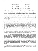
Fig. 15. Stator magnetic flux vector trajectory
7. Conclusion
DTC is intended for an efficient control of the torque and flux without changing the motor
parameters and load. Also the flux and torque can be directly controlled with the inverter
voltage vector in DTC. Two independent hysteresis controllers are used in order to satisfy
the limits of the flux and torque. These are the stator flux and torque controllers. DTC
process of the permanent magnet synchronous motor is explained and a simulation is
constituted. It is concluded that DTC can be applied for the permanent magnet synchronous
motor and is reliable in a wide speed range. Especially in applications where high dynamic
performance is demanded DTC has a great advantage over other control methods due to its
property of fast torque response. In order to increase the performance, control period should
be selected as short as possible. When the sampling interval is selected smaller, it is possible
to keep the bandwidth smaller and to control the stator magnetic flux more accurately. Also
it is important for the sensitivity to keep the DC voltage in certain limits.
As an improvement approach, a LP filter can be added to the simulation in order to
eliminate the harmonics. In simulation, certain stator flux and torque references are
compared to the values calculated in the driver and errors are sent to the hysteresis
comparators. The outputs of the flux and torque comparators are used in order to determine
the appropriate voltage vector and stator flux space vector.
When results with and without filters are compared, improvement with the filters is
remarkable, which will effect the voltage in a positive manner. Choosing cut off frequency
close to operational frequency decreases DC shift in the stator voltage. However, this leads
to phase and amplitude errors. Phase error in voltage leads to loss of control. Amplitude
error, on the other hand, causes voltage and torque to have higher values than the reference
values and field weakening can not be obtained due to voltage saturation. Hence, cutoff
frequency of LP filter must be chosen in accordance to operational frequency.
Direct Torque Control of Permanent Magnet Synchronous Motors
151
8. References
Adnanes, A. K. (1990). Torque Analysis of Permanent Magnet Synchronous Motors,
Proceedings of PESC, pp. 695-701, San Antonio, June 1990, Texas
Adreescu, G. D. & Rabinovici, R. (2004). Torque-speed adaptive observer and inertia
identification without current transducers for control of electrical drives.
Proc. of
the Romanian Academy Series A
, Vol. 5, No. 1, pp. 89-95, ISSN 1454-9069
Bekiroglu, N. & Ozcira, S. (2010). Observerless Scheme for Sensorless Speed Control of
PMSM Using Direct Torque Control Method with LP Filter.
Advances in Electrical
and Computer Engineering, Vol. 10, No. 3, pp. 78-83, ISSN 1582-7445
Balazovic, P. (2003). 3-Phase PM Synchronous Motor Torque Vector Control.
Application
Note DRM018, Motorola Czech System Laboratories Roznov pod Radhostem
Bolognani, S.; Oboe, R. & Zigliotto, M. (1999). Sensorless full-digital PMSM drive with EFK
estimation of speed and rotor position.
IEEE Trans. on Ind. Electronics, Vol. 46, No. 1,
pp. 184-191, ISSN 0278-0046
Chen, X.; Xu, D.; Liu, F. & Zhang, J. (2007) A Novel Inverter-Output Passive Filter for
Reducing Both Differential and Common-Mode dv/dt at the Motor Terminals in
PWM Drive Systems.
IEEE Transactions on Industrial Electronics, Vol. 54, No. 1, pp.
419-426, ISSN 0278-0046
Chern, T. L. & Wu, Y.C. (1993). Design of brushless DC position servo systems using integral
variable structure approach.
Electric Power Applications IEE Proceedings B Vol.140,
No.1, pp. 27-34, ISSN 1350-2352
Cui, J.; Wang, H.; Wang, C.; Wan, J. & Mu, G. (2008). Research on high performance direct
torque control system based on DSP,
Proceedings of 7th World Congress on Intelligent
Control and Automation WCICA, pp. 1494-1497, June 2008, IEEE, Chongqing
Dan, S.; Yikang, H. & Zhu, J. G. (2004). Sensorless direct torque control for permanent
magnet synchronous motor based on fuzzy logic, in
Proceedings of 4th International
Power Electronics and Motion Control Conference IPEMC, pp. 1286 – 1291, Aug. 2004,
Xi’an
Dariusz, S.; Martin, P. K. & Frede, B. (2002). DSP Based Direct Torque Control of Permanent
Magnet Synchronous Motor Using Space Vector Modulation,
Proceeding of the IEEE
International Symposium on Industrial Electronics ISIE, pp. 723-727, Nov 2002,
L'Aquila
Depenbrock, M. (1985). DTC leans on the theory of field-oriented control of induction
machines and the theory of direct self-control
Etz-Archive BD.7, H7, pp. 211-218
Depenbrock M. (1988). Direct Self-control of inverter-fed machine.
IEEE Transactions on
Power Electronics, Vol.3, No.4, pp. 420-429, ISSN 0885-8993
Geyer, T.; Beccuti, G. A.; Papafotiou, G. & Morari, M. (2010). Model Predictive Direct Torque
Control of Permanent Magnet Synchronous Motors,
Proceedings of IEEE Energy
Conversion Congress and Exposition ECCE, pp. 1-8, Sept 2010, Atlanta
Grzesiak L. M. & Kazmierkowski, M. P. (2007). Improving flux and speed estimators for
sensorless AC drives.
IEEE Industrial Electronics Magazine, Vol. 1, No. 3, pp. 9-19,
ISSN 1932-4529
Guo, Y.; Xianbing, C. & Chen, C. L. P. (2009). DTC-SVM-based Matrix Converter for a
PMSM in a Vessel Electric Propulsion System,
Proc. of the IEEE Control and Decision
Conference and Chinese Control Conference,
pp. 3397–3401, Dec 2009, Shanghai
Torque Control
152
Ichikawa, S.; Chen, Z.; Tomita, M.; Doki, S. & Okuma, S. (2003). Sensorless controls of
salient-pole permanent magnet synchronous motors using extended electromotive
force models.
Electrical Eng. in Japan, Vol. 146, No. 3, pp. 55-64, ISSN 1520-6416
Inoue, Y.; Morimoto, S. & Sanada, M. (2010). Examination and Linearization of Torque
Control System for Direct Torque Controlled IPMSM.
IEEE Transactions on Industry
Applications
, Vol. 46, No.1, pp. 159-166, ISSN 0093-9994
Jilong, Q.; Yantao, T.; Yimin, G. & Cheng, Z. (2008). A sensorless initial rotor position
estimation scheme and an Extended Kalman Filter observer for the direct torque
controlled Permanent Magnet Synchronous Motor Drive,
Proceedings of the
International Conference on Electrical Machines and Systems ICEMS
, pp. 3945 – 3950,
Oct 2008, IEEE, Wuhan
Jolly, L.; Jabbar, M.A. & Liu, Q. (2006). Optimization of The Constant Power Speed Range of
A Saturated Permanent-Magnet Synchronous Motor.
IEEE Transactions on Industry
Applications
, Vol. 42, No. 4, pp.1024-1030, ISSN 0093-9994
Laurila, L. (2004). Analysis of Torque and Speed Ripple Producing Non-idealities of
Frequency Converters in Electric Drives.
Disseration Lappeenranta University of
Technology, Stockholm
Li, Y.; Gerling, D. & Liu, W. (2008). A Novel Switching Table Using Zero Voltage Vectors for
Direct Torque Control in Permanent Magnet Synchronous Motor
18th International Conference on Electrical Machines ICEM, pp. 1-6, Vilamoura, Sept
2008, IEEE, Algarve
Liu, G.; Zhang, Y.; Chen, Z. & Jia, H. (2009). PMSM DTC Predictive Control System Using
SVPWM Based on the Subdivision of Space Voltage Vectors,
Proceedings of the IEEE
6th International Power Electronics and Motion Control Conference IPEMC
, pp. 1818-
1821, May 2009, Wuhan
Luukko, J. (2000). Direct Torque Control of Permanent Magnet Synchronous Machines-
Analysis and Implementation.
Disseration Lappeenranta University of Technology,
Stockholm
Luukko, J.; Niemela, M. & Pyrhonen, J. (2007). Estimation of Rotor and Load Angle of Direct
Torque Controlled Permanent Magnet Synchronous Machine Drive.
IET Electronics
Power Applications
, Vol.1, No. 3, pp. 209-306, ISSN 1751-8679
Martins, C.; Roboam, X.; Meynard, T. A. & Carylho, A. S. (2002). Switching Frequency
Imposition and Ripple Reduction in DTC Drives by A Multilevel Converter.
IEEE
Transactions on Power Electronics, Vol.17, pp. 286-297, ISSN 0885-8993
Matsui, N. & Ohashi, H. (1992). DSP-based adaptive control of a brushless motor.
IEEE
Transactions on Industry Applications
, Vol.28, No.2, pp. 448–454, ISSN 0093-9994
Noriega, G.; Restrepo, J.; Guzman, V. ; Gimenez, M. & Aller, J. (2007). Direct Torque Control
of PMSM using Fuzzy Logic with PWM,
Proceedings of 42nd International Universities
Power Engineering Conference UPEC, pp. 203-209, Sept 2007, IEEE, Brighton
Ogasawara, S. & Akagi, H. (1996). An approach to real-time position estimation at zero and
low speed for a PM motor based on saliency,
Proceedings on Industry Applications
Conference, pp. 29-35, San Diego, Oct 1996, IEEE, California
Omer, G. & Hava, A. (2010). Experimental investigation of shaft transducerless speed and
position control of AC induction and interior permanent magnet motors.
Turkish
Journal of Electrical Engineering & Computer Sciences, Vol.18, No.5, pp. 1-18, ISSN
1303-6203
Direct Torque Control of Permanent Magnet Synchronous Motors
153
Ozcira, S.; Bekiroglu, N. & Aycicek, E. (2008). Speed Control of Permanent Magnet
Synchronous Motor Based on Direct Torque Control Method,
Proceedings on
International Symposium on Power Electronics, Electrical Drives, Automation and Motion
SPEEDAM
, pp. 268-272, Ischia, June 2008, IEEE, Napoli
Ozcira, S.; Bekiroglu, N. & Aycicek, E. (2008). Direct Torque Control of Permanent Magnet
Synchronous Motor using LP Filter,
18th International Conference on Electrical
Machines ICEM
, pp. 1-5, Vilamoura, Sept 2008, IEEE, Algarve
Pelczewski, P. M.; Oberschelp, W. & Kunz, U. H. (1991). Optimal Model-Following Control
of a Positioning Drive System with a Permanent-Magnet Synchronous Motor,
IEE
Proceedings on Control Theory and Applications
Vol.138, No.3, pp. 267 – 273, ISSN
1350-2379
Pillay, P. & Krishnan, R. (1989). Modeling, Simulation, and Analysis of Permanent-Magnet
Motor Drives Part II: The brushless DC Motor Drive.
IEEE Transactions on Industry
App, Vol.25, No.2, pp. 274-279, ISSN 0093-9994
Popescu, M.; Miller, T.J.E.; McGilp, M. I.; Strappazzon, G.; Trivillin, N. & Santarossa, R.
(2006). Torque Behavior of One-Phase Permanent-Magnet AC Motor.
IEEE
Transactions on Energy Conversion
, Vol. 21, No. 1, pp. 19-26, ISSN 0885-8969
Rahman K. M. & Toliyat, H. A. (1996). Sensorless operation of permanent magnet AC
(PMAC) motors with modified stator windings,
Procs in Conference Records IEEE-
IAS 31st Annual Meeting
, pp. 326-333, San Diego, Oct. 1996, IEEE, California
Rahman, M. F.; Zhong, L. & Lim, K. W. (1998). A direct torque-controlled interior permanent
magnet synchronous motor drive incorporating field weakening.
IEEE Transactions
on Industry Applications, Vol.34, No.6, pp. 1246-1253, ISSN 0093-9994
Rahman, M. F.; Zhong, L. & Haque, E. (1999). Selection of Voltage Switching Tables for DTC
Controlled Interior Permanent Magnet Motor.
School of Electrical Engineering and
Telecommunications Lect. The University of New South Wales, Sydney
Raymond, B. & Lang, J. H. (1991). Real-time Adaptive Control of the Permanent-Magnet
Synchronous Motor.
IEEE Transactions on Industy Applicaitons, Vol. 27, No. 4, pp.
704-716, ISSN 0093-9994
Sanchez, E.; Al-rifai, F. & Schofield, N. (2009). Direct Torque Control of Permanent Magnet
Motors using a Single Current Sensor,
Proceedings of the IEEE International Electric
Machines and Drives Conference IEMDC
, pp. 89-94, May 2009, Miami
Siahbalaee, J.; Vaez-Zadeh, S. & Tahami, F. (2009). A New Loss Minimization Approach
With Flux And Torque Ripples Reduction of Direct Torque Controlled Permanent
Magnet Synchronous Motors,
Proceedings of 13th European Conference on Power
Electronics and Applications EPE, pp. 1-8, Sept 2009, IEEE, Barselona
Sozer, Y.; Torrey, D. A. & Reva, S. (2000). New inverter output filter topology for PWM
motor drives,
IEEE Transactions on Power Electronics, Vol. 15, No. 6, pp. 1007-1017,
ISSN 0885-8993
Swierczynski, D.; P. Wojcik, P.; Kazmierkowski, M. P. & Janaszek, M. (2008). Direct Torque
Controlled PWM Inverter Fed PMSM Drive for Public Transport,
Proceedings on
IEEE International Workshop on Advanced Motion Control AMC
, pp. 716-720, March
2008, Trento
Takahashi, I. & Noguchi, T. (1986). A New Quick-Response and High-Efficiency Control
Strategy of an Induction Motor.
IEEE Transactions on Industry Applications, Vol. IA-
22, No.5, pp. 820-827, ISSN 0093-9994
Torque Control
154
Tan, Z.; Li, Y. & Li, M. (2001). A Direct Torque Control of Induction Motor Based on Three
Level Inverter,
Proceedings of PESC, pp. 1435–1439, June 2001, IEEE, Vancouver
Tang, L.; Zhong, L.; Rahman, M. F. & Hu, Y. (2004). A Novel Direct Torque Controlled
Interior Permanent Magnet Synchronous Machines Drive with Low Ripple in Flux
and Torque and Fixed Switching Frequency.
IEEE Transactions on Power Electronics
Vol. 19, No. 2, pp.346-354, ISSN 0885-8993
Toliyat, H. A.; Hao, L.; Shet, D. S. & Nondahl, T. A. (2002). Position-sensorless control of
surface-mount permanent-magnet AC (PMAC) motors at low speeds.
IEEE Trans.
on Industrial Electronics,
Vol. 49, No. 1, pp. 157-164, ISSN 0278-0046
Vaez-Zadeh, S. (2001). Variable Flux Control of Permanent Magnet Synchronous Motor
Drives for Constant Torque Operation.
IEEE Transactions on Power Electronics, Vol.
16, No.4, pp. 527-534, ISSN 0885-8993
Vas, P. (1998).
Sensorless Vector and Direct Torque Control, Oxford University Press, ISBN 0-
19-856465-1, New York.
Wang, L. & Gao, Y. (2007). A Novel Strategy of Direct Torque Control for PMSM Drive
Reducing Ripple in Torque and Flux,
Proceedings of IEEE International Electric
Machines & Drives Conference IEMDC, pp. 403-406, May 2007, Antalya
Yan, Y.; Zhu, J. & Lu, H. (2005). Direct torque control of surface-mounted permanent magnet
synchronous motor based on accurate modeling,
Proceedings of Australasian
Universities Power Engineering Conference AUPEC, Sept. 2005, Tasmania
Yutao, L.; Fanzhen, M.; Xingfeng, F. & Peng, K. (2008). The Rectangular Fluctuation Control
of Improved Direct Torque Controlled Permanent Magnet Synchronous Machines
Based on RBF Network,
Proceedings of 27th Chinese Control Conference, CCC, pp. 628-
631, July 2008, Kunming
Zhao, L.; Ham, C. H.; Wu, T. X.; Zheng L.; Sundaram, K.B.; Kapat, J. & Chow, L. (2004).
DSP-Based Super High-Speed PMSM Controller Development and Optimization.
Digital Signal Processing Workshop and the 3rd IEEE Signal Processing Education
Workshop
, pp. 187- 190, August 2004, New Mexico
Zhao, S. & Peng, S. (2007). A Modified Direct Torque Control Using Space Vector
Modulation (DTC-SVM) for Surface Permanent Magnet Synchronous Machine
(PMSM) with Modified 4-order Sliding Mode Observer,
Proc. of IEEE International
Conference on Mechatronics and Automation ICMA
, pp. 1207-1212, August 2007,
Heilongjiang
Zhong, L.; Rahman, M. F.; Hu, W. Y. & Lim, K. W. (1997). Analysis of Direct Torque Control
in Permanent Magnet Synchronous Motor Drives.
IEEE Trans. on Power Electronics,
Vol.12, No.3, pp. 528-536, ISSN 0885-8993
Zhong, L.; Rahman, M. F.; Hu, W. Y.; Lim, K. W. & Rahman, M. A. (1999). A Direct Torque
Controller for Permanent Magnet Synchronous Motor Drives.
IEEE Transactions on
Energy Conversion, Vol.14, No.3 pp. 637-642, ISSN 0885-8969
7
Torque Control of PMSM and
Associated Harmonic Ripples
Ali Ahmed Adam
1
, and Kayhan Gulez
2
1
Fatih University, Engineering Faculty, Electrical-Electronics Eng. Dept., 34500
Buyukcekmece-Istanbul,
2
Yildiz Technical University, Electrical-Electronics Eng. Faculty, Control and Automation
Engineering Dept., 34349 Besiktas- Istanbul,
Turkey
1. Introduction
Vector control techniques have made possible the application of PMSM motors for high
performance applications where traditionally only dc drives were applied. The vector
control scheme enables the control of the PMSM in the same way as a separately excited DC
motor operated with a current-regulated armature supply where then the torque is
proportional to the product of armature current and the excitation flux. Similarly, torque
control of the PMSM is achieved by controlling the torque current component and flux
current component independently.
Torque Control uses PMSM model to predict the voltage required to achieve a desired output
torque or speed. So by using only current and voltage measurements (and rotor position in
sensor controled machine), it is possible to estimate the instantaneous rotor or stator flux and
output torque demanded values within a fixed sampling time. The calculated voltage is then
evaluated to produce switching set to drive the inverter supplying the motor. PMSM torque
control has traditionally been achieved using Field Oriented Control (FOC). This involves the
transformation of the stator currents into a synchronously rotating d-q reference frame that is
typically aligned to the rotor flux. In the d-q reference frame, the torque and flux producing
components of the stator current can separately be controlled. Typically a PI controller is
normally used to regulate the output voltage to achieve the required torque.
Direct Torque Control (DTC), which was initially proposed for induction machines in the
middle of 1980’s (Depenbrock, 1984 and 1988; Takahashi, 1986), was applied to PMSM in the
late 1990's (French, 1996; Zhong, 1997). In the Direct Torque Control of the PMSM, the
control of torque is exercised through control of the amplitude and angular position of the
stator flux vector relative to the rotor flux vector. Many methods have been proposed for
direct torque control of PMSM among which Hysteresis based direct torque control (HDTC)
and Space Vector Modulation direct torque control (SVMDTC).
In 2009 Adam and Gulez, introduced new DTC algortim for IPMSM to improve the
performance of hysteresis direct torque control. The algorithm uses the output of two
hysteresis controllers used in the traditional HDTC to determine two adjacent active vectors.
The algorithm also uses the magnitude of the torque error and the stator flux linkage
position to select the switching time required for the two selected vectors. The selection of
Torque Control
156
the switching time utilizes suggested table structure which, reduce the complexity of
calculation. The simulation and experimental results of the proposed algorithm show
adequate dynamic torque performance and considerable torque ripple reduction as well as
lower flux ripple, lower harmonic current and lower EMI noise reduction as compared to
HDTC. Only two hysteresis controllers, current sensors and built-in counters
microcontroller are required to achieve torque control.
Torque ripple and harmonic noise in PMSM are due to many factors such as structural
imperfectness associated with motor design, harmonics in control system associated with
measurement noises, switching harmonics and harmonic voltages supplied by the power
inverter which constitute the major source of unavoidable harmonics in PMSM. These
harmonics cause many undesired phenomena such as electromagnetic interference “EMI”
and torque ripples with consequences of speed oscillations, mechanical vibration and
acoustic noise which, deteriorate the performance of the drive in demanding applications
(Holtz and Springob 1996). These drawbacks are especially high when the sampling period
is greater than 40μs (Zhong, et al. 1997).
Recently many research efforts have been carried out to reduce the torque ripples and
harmonics in PMSM due to inverter switching with different degree of success. Yilmaz
(Yilmaz, et al. 2000) presented an inverter output passive filter topology for PWM motor
drives to reduce harmonics of PMSM, the scheme shows some effectiveness in reducing
switching harmonics, but however, very large circulating current between inverter output
and filter elements is required to reshape the motor terminal voltage which violate current
limitation of the inverter. Many researchers (Hideaki et al, 2000; Darwin et al., 2003; Dirk et
al , 2001) have addressed active filter design to reduce or compensate harmonics in supply
side by injecting harmonics into the line current which have no effect on the current
supplying the load. Satomi (Satomi, et al. 2001) and Jeong-seong (Jeong-seong, et al. 2002)
have proposed a suppression control method to suppress the harmonic contents in the d-q
control signals by repetitive control and Fourier transform but, however, their work have
nothing to do with switching harmonics and voltage harmonics provided by the PWM
inverter supplying the motor. Se- Kyo, et al. (1998), Dariusz et al. (2002), and Tang et, al.
(2004) have used space vector modulation to reduce torque ripples with good results;
however, their control algorithm depends on sophisticated mathematical calculations and
two PI controllers to estimate the required reference voltage and to estimate the switching
times of the selected vectors. Holtz and Springob (1996, 1998) presented a concept for the
compensation of torque ripple by a self- commissioning and adaptive control system.
In this chapter, two different methods to improve torque ripple reduction and harmonic
noises in PMSM will be presented. The first method is based on passive filter topology
(Gulez et al., 2007). It comprises the effects of reducing high frequency harmonic noises as
well as attenuating low and average frequencies. The second method is based on active
series filter topology cascaded with two LC filters (Gulez et al., 2008).
Modern PMSM control algorthims
2. Algorithm 1: Rotor Field Oriented Control “FOC”
The control method of the rotor field-oriented PMSM is achieved by fixing the excitation
flux to the direct axis of the rotor and thus, it is position can be obtained from the rotor shaft
by measuring the rotor angle θ
r
and/or the rotor speed ω
r
.
Consider the PMSM equations in rotor reference frame are given as:
Torque Control of PMSM and Associated Harmonic Ripples
157
0
sd r sq
sd sd
sq
sq
rsd s
q
rF
RpL PL
vi
i
v
PL RpL P
ω
ωωψ
+−
⎡⎤
⎡⎤
⎡⎤
⎡
⎤
=+
⎢⎥
⎢⎥
⎢⎥
⎢
⎥
+
⎢⎥
⎣
⎦⎢⎥
⎣⎦⎣⎦
⎣⎦
3
(( )))
2
eFs
q
sd s
q
sd s
q
TPiLLii
ψ
=+−
(1)
Where,
v
sd
, v
sq
: d-axis and q-axis stator voltages;
i
sd
, i
sq
: d-axis and q-axis stator currents;
R: stator winding resistance;
L
sd
, L
sq
: d-axis and q-axis stator inductances;
p=d/dt: differential operator;
P: number of pole pairs of the motor;
ω
r
: rotor speed;
Ψ
F
: rotor permanent magnetic flux;
Te: generated electromagnetic torque;
To produce the largest torque for a given stator current, the stator space current is controlled
to contain only i
sq
.
And since for PMSM L
d
≤ L
q
, the second torque component in Eq.(1) is negative with
positive values of i
sd
and zero for SPMSM. Thus, to ensure maximum torque, the control
algorithm should be such that i
sd
is always zero, which result in simple torque expression as:
T
e
=3/2 P
ψ
F
i
sq
=3/2
ψ
F
| i
s
| sin(
α
-θ
r
) (2)
The stator windings currents are supplied from PWM inverter, using hysteresis current
controller. The actual stator currents contain harmonics, which, produce pulsating torques,
but these may be filtered out by external passive and active filters, or using small hysteresis
bands for the controllers.
2.1 Implementation of rotor field oriented control
The block diagram of rotor-field oriented control of PMSM in polar co-ordinate is shown in
Fig.1 (Vas, 1996). The stator currents are fed from current controlled inverter. The measured
stator currents are transformed to stationary D-Q axis. The D and Q current components are
then transformed to polar co-ordinate to obtain the modulus |i
s
| and the phase angle
α
s
of the
stator-current space phasor expressed in the stationary reference frame.
Fig. 1. Rotor Field Oriented Control of PMSM
Torque Control
158
The rotor speed
ω
r
and rotor angle
θ
r
are measured; and the position of the stator current in
the rotor reference frame is obtained. Then, the instantaneous electromagnetic torque Te can
be obtained as stated in Eq. (2).
The necessary current references to the PWM inverter are obtained through two cascaded PI
controllers. The measured rotor speed
ω
r
is compared with the given reference speed
ω
ref
and the error is controlled to obtained the reference torque T
eref
. The calculated torque is
subtracted from the reference torque and the difference is controlled to obtain the modulus
of i
sref
. The reference angle
α
sref
is set equal to π/2, and the actual rotor angle is added to
(α
sref
− θ
r
) to obtain the angle α
sref
of the stator current in the stationary D-Q frame. Theses
values are then transformed to the three-reference stator currents i
sAref,
i
sBref
and i
sCref
and
used to drive the current controller.
The functions of the PI controllers (other controllers such as Fuzzy Logic, Adaptive, Slide
mode or combinations of such controller may be used) are to control both the speed and
torque to achieve predetermined setting values such as:
1. Zero study state error and minimum oscillation,
2. Wide range of regulated speed,
3. Short settling time,
4. Minimum torque ripples,
5. Limited starting current.
Based on the above description a FOC model was built in MatLab/Simulink as shown in
Fig. 2. The model responses for the data setting in Table 1 of SPMSM with ideal inverter
were displayed in Fig.3 to Fig.7. The PI controllers setting and reference values are:
Ts=1 μs, ω
ref
=300, T
L
=5Nm, PI
2
: Kp=10, Ki=0.1 PI
1
: Kp=7, Ki=0.1.
Fig. 2. FOC model in Matlab/Simulink
Torque Control of PMSM and Associated Harmonic Ripples
159
Fig. 3. Torque response
Fig. 4. Speed response
Fig. 5. Line current response
Torque Control
160
Fig. 6. V
ab
switching pattern
Fig. 7. Regulated Speed range (0-450) rad/s
Vdc 120V
Ψ
F
0.1546 web.
Rs 1.4 ohm
Ld 0.0066 H
Lq 0.0066 H
J 0.00176 kGm
2
B 0.000388 N/rad/s
Table 1. Motor parameters
The above figures show acceptable characteristics however, the torque pulsation cannot be
avoided and the line currents are almost sinusoidal with some harmonic values. The speed
can be regulated up to the rated value (300rad/s) with acceptable response. Bearing in mind
that sensors, analog/digital converters, switching elements of the inverter and algorithm
Torque Control of PMSM and Associated Harmonic Ripples
161
processing in DSP are time consuming, it is practically difficult to achieve such system with
small sampling period. Thus, in practice convenient sampling periods, such as 100 μs (or
larger) is normally selected for processing. In the following, simulation practical values will
be adopted to obtain reasonable results for comparison. So, PMSM with parameters shown
in Table 2 was simulated in the same model with the following setting values:
Ts=100 μs, T
L
=2Nm, ω
ref
=70 rad/s PI
2
: Kp=10, Ki=0.1 and PI
1
: Kp=7, Ki=0.1
Number of pole pairs P 2
Stator leakageresistance R
s
5.8 Ohm
d-axis inductance L
sq
102.7 mH
q-axis inductance L
sd
44.8 mH
Permanent magnet flux Ψ
F
533 mWb
Inertia constant J 0.000329Nms
2
Friction constant B 0.0
Reference speed ω 70 rad/s
Load torque T
L
2 Nm
Table 2. IPMSM parameters
The simulation responses were shown below:
Fig. 8. FOC Torque response
Fig. 9. FOC Speed response
Torque Control
162
Fig. 10. FOC Line Voltage Switching
Fig. 11. FOC Current response
Fig. 12. Flux response
The responses showed that the torque pulsation is very high and line currents are full of
harmonic components which give rise to EMI noises, in addition flux and speed are not free
of ripples which result in unwanted phenomena such as machine vibration and acoustic
noise.
Torque Control of PMSM and Associated Harmonic Ripples
163
3. Algorithm 2: Hysteresis Direct Torque Control (HDTC)
This method which is also called Basic DTC can be explained by referring to Fig.13. In this
figure, the angle between the stator and rotor flux linkages δ is the load angle when the
stator resistance is neglected. In the study, state δ is constant corresponds to a load torque,
where stator and rotor flux rotate at synchronous speed. In transient operation, δ varies and
the stator and rotor flux rotate at different speeds. Since the electrical time constant is
normally much smaller than the mechanical time constant, the rotating speed of stator flux
with respect to rotor flux, can easily be changed also that the increase of torque can be
controlled by controlling the change of δ or the rotating speed of the stator flux (Zhong,
1997) as will be explained in the following analysis.
q
Q
ψ
sref
L
d
i
sd
i
s
i
sq
ψ
s
β-axis α-axix
L
q
i
sq
λ
s
λ
sref
δ Ψ
F
d Rotor direct axis
θ
D Stator direct axis
Fig. 13. Stator and rotor flux space phasors
3.1 Flux and torque criteria
Referring to Fig. 13 the flux equations in rotor dq axis frame can be rewritten as:
cos
sd sd sd F s
Li
ψ
ψψ δ
=+= (3)
sin
sq sq sq s
Li
ψ
ψδ
==
(4)
Where, |ψ
s
| represent the amplitude of the stator flux linkage calculated as:
()
(
)
2
22
ssdsdF sqsd
Li Li
ψψ
=++ (5)
In the general α-β reference frame the torque equation can be written as (Zhong, 1997):
e
3
T
2
ss
Pi
β
ψ
= (6)
Where; i
β
is the component of the stator phasor space current perpendicular to the stator flux
axis α.
Equation (6) suggests that the torque is directly proportional to the β-axis component of the
stator current if the amplitude of the stator flux linkage is kept constant.
Now using Eq.(3) and Eq.(4) to rewrite the torque equation as:
Torque Control
164
()
3
2sin sin2
4
s
eFsqssqsd
sd sq
P
TLLL
LL
ψ
ψ
δψ δ
⎡
⎤
=−−
⎣
⎦
(7)
For SPMSM L
sd
= L
sq
= L
s
and this expression is reduced to
3
sin
2
s
eF
s
P
T
L
ψ
ψ
δ
=
=
3
sin
2
s
F
s
P
t
L
ψ
ψ
δ
•
(8)
Where δ
•
is the angular speed of the stator flux linkage relative to the permanent magnet
axis.
At constant flux values, Eq. (8) shows that T
e
-δ has sinusoidal relationship and the
derivative of this equation suggest that the increase of torque is proportional to the increase
of δ in the range of –π/2 to π/2. So the stator flux linkage should be kept constant and the
rotational speed δ
•
is controlled as fast as possible to obtain the maximum change in actual
torque.
For IPMSM, the torque expression contains in addition to the excitation torque, reluctance
torque and for each stator flux level value, there exist different T
e
-δ curve and different
maximum torque. Fig. 14 (Zhong, 1997) shows these relationship for different values of
|ψ
s
|. Observe the crossing of curve |ψ
s
|=2ψ
F
where, the derivative of torque near zero
crossing has negative value, which implies that DTC can not be applied in this case.
Fig. 14. Different T
e
-δ curves for different stator flux values
Analytically this condition can be obtained from derivative of Eq. (7) as follows:
()
3
2
s
e
Fsq s sq sd
sd sq
P
dT
LLL
dt L L
ψ
ψ
δψ δ
•
∗
⎡
⎤
=−−
⎣
⎦
(9)
And thus for positive torque derivative under positive δ
•
, |ψ
s
| should be selected in such a
way that (Tang et al., 2002; Zhong et al. 1997):
F
sdsq
sq
s
LL
L
ψψ
−
〈
(10)
Torque Control of PMSM and Associated Harmonic Ripples
165
That if fast dynamic response is required. Also that (Tang et al., 2002) for stable torque
control the following criteria should be satisfied.
2
1
/(/)8
cos ( )
4
ss
aa
ψψ
δ
−
−
+
< (11)
Where, a =
sq
F
sq sd
L
LL
ψ
−
3.2 Control of stator flux strategy
The stator flux linkage of a PMSM in the stationary reference frame can be expressed as:
0
()
sss s sst
VRidtVtRidt
ψψ
=
=− =− +
∫∫
(12)
During switching interval each voltage vector is constant, so if stator resistance is neglected
then, this equation implies that the stator flux will move in the direction of the applied
voltage vector.
To select the voltage vectors or controlling the amplitude of the stator flux linkage, the
voltage vector plane is divided into six sectors (FS
1
to FS
6
) as shown in Fig. 15. In each
region two adjacent voltage vectors are selected to increase or decrease the amplitude
respectively of the flux within a hysteresis band. For example, the vectors V
2
and V
3
are
used to increase and decrease the flux amplitude when ψ
s
is in region one and rotating in a
counter clockwise direction. If rotating in clockwise direction then V5 and V6 are used for
the same reason.
V
6
(101)
V
2
(110)
V
3
(010)
V
4
(011)
V
5
(001)
V
1
(100)
V
0
(000)
V
7
(111)
FS=1
FS=2FS=3
FS=6
FS=4
FS=5
Fig. 15. Applied vectors position and flux sectors.
3.3 Implementation of Hysteresis DTC
The block diagram of a PMSM drive with HDTC may be as shown in Fig. 16, where the
measured current phase values and dc voltage are transferred to D-Q stationary axis values,
and the flux linkage components ψ
sD
and ψ
sQ
at the m
th
sampling instance are calculated
from the stator voltages as follows:
ψ
sD
(m)= ψ
sD
(m-1) +(V
D
(m-1)-Ri
sD
)Ts (13)
Torque Control
166
ψ
sQ
(m)= ψ
sQ
(m-1) +(V
Q
(m-1)-Ri
sQ
)Ts (14)
Where Ts is the sampling period and i
sD
and i
sQ
are calculated as average values of i
s
(m-1)
and i
s
(m) and thus, amplitude and flux angle position with respect to stationary D-Q axis
can be calculated as:
22
1
() ()
()
tan
()
sD Q
Q
s
D
mm
m
m
ψψ ψ
ψ
λ
ψ
−
=+
=
(15)
The torque can be rewritten in the stationary reference frame as (Zhong et al., 1997):
()
3
() () () () ()
2
esDsQsQsD
Tm P mi m mi m
ψψ
=−
(16)
However if the phase currents and the rotor speed and/or rotor position are monitored then
Eq. (3) and Eq. (4) can be used to calculate torque and flux values, where then the
transformation D-Q ↔ d-q is necessary to achieve the required values.
Fig. 16. HDTC of PMSM
The calculated Torque and Flux magnitude values are compared with their respective
reference values and the produced errors are inputs to their respective hysteresis
comparators. The flux linkage comparator is a two level comparator
φ
ε
{1, 0} and the torque
comparator is a three level comparator
τ
ε
{1, 0, -1}. The outputs of these comparators
together with stator position λ
s
(or sector number) are inputs to optimum voltage switching
lookup table as the one shown in Table 3 (Luukko, 2000). The output of this table is
switching vector to the inverter driving the motor.
Based on the above description a HDTC of PMSM model was built in Matlab Simulink as
shown in Fig.17.
The torque and flux estimator is based on monitoring of phase currents and rotor angle. The
model responses for the Table 2 and controllers setting values as:
PI speed controller: Kp=0.04 and Ki=2,
Hysteresis logic: Flux band = ± 0.01; Torque Band = ±0.01; Sampling time: Ts= 0.0001s; has
been simulated with results displayed in Fig.18-Fig.22
Torque Control of PMSM and Associated Harmonic Ripples
167
FS
ф τ
1
-30≤ λ
s
<30
2
30≤ λ
s
<90
3
90≤ λ
s
<150
4
150≤ λ
s
<210
5
210≤ λ
s
<270
6
270≤ λ
s
<330
1 V
2
(110) V
3
(010) V
4
(011)
V
5
(001)
V
6
(101)
V
1
(100)
0 V
7
(111) V
0
(000) V
7
(111) V
0
(000) V
7
(111) V
0
(000)
1
-1 V
6
(101) V
1
(100) V
2
(110) V
3
(010) V
4
(011) V
5
(001)
1 V
3
(010) V
4
(011) V
5
(001) V
6
(101) V
1
(100) V
2
(110)
0 V
0
(000) V
7
(111) V
0
(000) V
7
(111) V
0
(000) V
7
(111)
0
-1 V
5
(001) V
6
(101) V
1
(100) V
2
(110) V
3
(010) V
4
(011)
Table 3. Optimum switching lookup table for HDTC inverter. Ф is the output of flux
hysteresis controller, τ is the output of the torque hysteresis controller, the entries V
i
(…) is
the switching logic to the inverter and FS (Flux Sector) define the stator flux position sector
Fig. 17. HDTC of PMSM in Matlab/Simulink
Fig. 18. Torque Response
Torque Control
168
Fig. 19. Speed Response
Fig. 20. Voltage switching of line a-b
Fig. 21. HDTC Line current of phase-a