SHEAR STRENGTH AND ARTIFICIAL AGING CHARACTERIZATION FOR SILICONE
Bạn đang xem bản rút gọn của tài liệu. Xem và tải ngay bản đầy đủ của tài liệu tại đây (966.6 KB, 60 trang )
SHEAR STRENGTH AND ARTIFICIAL AGING
CHARACTERIZATION FOR SILICONE BONDING OF
POLYISOBUTYLENE (PIBS) BLENDS IN RELATION TO
THEIR USE AS LEAD INSULATION MATERIAL
A Thesis
Presented to the Faculty of
California Polytechnic State University
San Luis Obispo
In Partial Fulfillment of the Requirements
For the Degree
Master of Science in Biomedical Engineering
By Shawn Grening
February 2009
ii
© 2009
SHAWN GRENING
ALL RIGHTS RESERVED
iii
COMMITTEE PAGE
TITLE: SHEAR STRENGTH AND ARTIFICIAL AGING
CHARACTERIZATION FOR SILICONE BONDING
OF POLYISOBUTYLENE (PIBS) BLENDS IN
RELATION TO THEIR USE AS LEAD INSULATION
MATERIAL
AUTHOR: Shawn Grening
DATE SUBMITTED: May, 2009
COMMITTEE CHAIR: Robert Crocket, Associate Professor
COMMITTEE MEMBER: Lily Hsu Laiho, Assistant Professor
COMMITTEE MEMBER: Daniel W. Walsh, Associate Dean, College of
Engineering
iv
ABSTRACT
SHEAR STRENGTH AND ARTIFICIAL AGING
CHARACTERIZATION FOR SILICONE
BONDING OF PIBS BLENDS IN RELATION
TO THEIR USE AS LEAD INSULATION MATERIAL
Shawn Grening
In order to take advantage of the properties of poly(styrene-isobutylene-styrene) PIBS and PIB
based blends as lead insulation materials, they must be able to sufficiently bond to the various
materials that make up the cardiac device. The bonded PIBS must be able to withstand the
mechanical stress and corrosive environment of the human body due to the long term use of these
devices. Based on the component requirements of lead insulation, the first objective of this study
was to perform an initial screening of multiple PIBS / stainless steel / silicone adhesive
combinations. The specific polymers of interest were PIBS, 10%55D polyurethane, 10%75D
polyurethane, 10%PP, and a silicone control. Based on the bonding shear strength results of the
initial screening, the best performing combinations were artificially aged to simulate their
resistance to degradation in vivo. Each combination was subjected to both 3% hydrogen peroxide
and Phosphate Buffered Saline solutions for a period of 8 weeks to test for oxidative and
hydrolytic stability. Bonding shear strengths for all sample groups were tested at each 2-week
period. The 10%55D sample group had the highest mean bonding shear strength at .5602 MPa,
but to observe the aging stability of all sample groups, all combinations were used in Phase II.
The phosphate buffered saline solution in Phase II caused no significant decrease in bonding
shear strength for all sample groups. Alternatively, oxidation caused by the 3% hydrogen
peroxide solution did significantly affect the bonding shear strengths of all sample groups (minus
the silicone control). Over the 8-week period PIBS degraded 28% and 10%55D and 10%75D
decreased 40.0% and 30.8%, respectively. 10%PP degraded 32.0% and the silicone control
remained relatively unchanged.
v
TABLE OF CONTENTS
LIST OF FIGURES VI
LIST OF TABLES VII
BACKGROUND 1
1.1. IMPLANTABLE CARDIAC RHYTHM MANAGEMENT DEVICES 1
1.1.1. Purpose 1
1.1.2. Components and Design 2
1.1.3. Failure Modes 3
1.2. LEAD INSULATION MATERIALS AND ADHESIVES 4
1.2.1. Silicone 4
1.2.2. Polyurethane 5
1.2.3. Poly (styrene-isobutylene-styrene) (PIBS) 6
1.2.4. PIBS Blends – Polypropylene (PP) 8
1.2.5. PIBS Blends – Polyurethane (PU) 8
1.2.6. Silicone Adhesive 9
1.2.7. Primer 10
1.3. DEGRADATION OF POLYMERS 12
1.3.1. Environment of the Human Body 12
1.3.2. Hydrolysis 12
1.3.3. Oxidation 13
2. PURPOSE AND EXECUTION OF STUDY 14
2.1. PHASE I: INITIAL SCREENING 14
2.1.1. Objective and Deliverables 14
2.1.2. Materials and Equipment 15
2.1.3. Procedure and Methodology 15
2.2. PHASE II: AGING STABILITY 18
2.2.1. Objectives and Deliverables 18
2.2.2. Materials and Equipment 18
2.2.3. Procedure and Methodology 19
3. RESULTS 21
3.1. PHASE I RESULTS 21
3.1.1. Statistical Summary 21
3.1.2. Statistical Analysis 22
3.1.3. Process Issues 25
3.2. PHASE II RESULTS 25
3.2.1. Statistical Summary 25
3.2.2. Statistical Analysis 34
3.2.3. Process Issues 35
4. DISCUSSION 36
4.1. PHASE I – INITIAL BONDING SHEAR STRENGTH 36
4.2. PHASE II – AGING STABILITY 39
5. CONCLUSION 42
6. REFERENCES 44
APPENDIX A 46
vi
LIST OF FIGURES
FIGURE 1. SCHEMATIC OF IMPLANTED PACEMAKER
5
2
FIGURE 2. SEGMENTS OF THE POLY(STYRENE-ISOBUTYLENE-STYRENE) TRI-BLOCK
COPOLYMER
14
6
FIGURE 3. SILANE PRIMER ADHESION PROMOTION 11
FIGURE 4. ADHESIVE QUANTITY REFERENCE. 16
FIGURE 5. LLOYD LF PLUS TENSILE TESTER WITH GRIPPERS 17
FIGURE 6. LAB OVEN AND TEST TUBE SETUP 20
FIGURE 7. PHASE I INITIAL BONDING SHEAR STRENGTH BOX PLOTS 22
FIGURE 8. PHASE I PROBABILITY PLOT FOR EACH SAMPLE GROUP SHOWING
NORMALITY 23
FIGURE 9. PHASE I TEST FOR EQUAL VARIANCES 24
FIGURE 10. PIBS/SS BONDING SHEAR STRENGTH (MPA) VS. AGING TIME (WEEKS)
FOR PBS AND H
2
O
2
28
FIGURE 11. 10%PP/SS BONDING SHEAR STRENGTH (MPA) VS. AGING TIME (WEEKS)
FOR PBS AND H
2
O
2
29
FIGURE 12. 10%55D/SS BONDING SHEAR STRENGTH (MPA) VS. AGING TIME (WEEKS)
FOR PBS AND H
2
O
2
30
FIGURE 13. 10%75D/SS BONDING SHEAR STRENGTH (MPA) VS. AGING TIME (WEEKS)
FOR PBS AND H
2
O
2
31
FIGURE 14. SILICONE/SS BONDING SHEAR STRENGTH (MPA) VS. AGING TIME (WEEKS)
FOR PBS AND H
2
O
2
32
FIGURE 15. WEEK 8 BOX PLOTS OF BONDING SHEAR STRENGTHS 33
FIGURE 16. WETTING ANGLE OF ADHESIVE ON SUBSTRATE SHOWING BAD AND
GOOD
27
36
FIGURE 17. INITIAL MEAN BONDING SHEAR STRENGTHS WITH RELATIVE SURFACE
ENERGY VALUE 38
FIGURE 18. ADHESIVE ON STAINLESS STEEL NEEDLE FOLLOWING BOND FAILURE 39
vii
LIST OF TABLES
TABLE 1 - TYPICAL PROPERTIES OF SILASTIC BIOMEDICAL GRADE ETR ELASTOMERS
11
5
TABLE 2 - PROPERTIES COMPARISON OF SIBSTAR® GRADES.
18
8
TABLE 3 - TYPICAL PROPERTIES OF THE NUSIL MED-2000 SILICONE ADHESIVE
22
10
TABLE 4 - TYPICAL PROPERTIES OF THE NUSIL SP-135 SILANE PRIMER
24
11
TABLE 5 - PHASE I BONDING SHEAR STRENGTH STATISTICAL SUMMARY 21
TABLE 6 - TWO SAMPLE T-TEST FOR SIGNIFICANT DIFFERENCE BETWEEN PHASE I
MEAN BONDING SHEAR STRENGTHS FOR EACH GROUP 25
TABLE 7 - PHASE II BONDING SHEAR STRENGTH DATA 26
TABLE 8 - TWO SAMPLE T-TEST RESULTS FOR DIFFERENCE IN MEAN BONDING SHEAR
STRENGTH BETWEEN WEEK 0 AND WEEK 8 34
TABLE 9 - SURFACE ENERGIES OF RELEVANT MATERIALS 37
1
BACKGROUND
1.1. Implantable Cardiac Rhythm Management Devices
1.1.1. Purpose
Patients with abnormal heart rhythms (cardiac arrhythmias) are often treated with
implantable medical devices that deliver an electrical impulse to help restore their normal heart
beat. The two most common devices are pacemakers and implantable cardioverter defibrillators
(ICDs). The primary purpose of a pacemaker is to treat a condition called bradycardia, which is a
heart rate that is too slow caused by a reduced rate of Sinoatrial Node (SA) firing. Long-term
implantation is performed with minimally invasive surgery under local anesthesia and generally
requires less than 45 minutes. The electrodes are placed in the heart through one of the large
subclavian veins in the chest and after external testing the small generator is placed under the skin
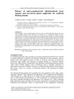
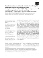
(Figure 1). Modern pacemakers are externally programmable and allow the physician to select
optimum pacing modes for each patient. An ICD is a device implanted like a pacemaker that
monitors the patient’s heart rhythm and waits for an arrhythmia. When it detects a tachycardia (a
heart rate that is too fast), the ICD delivers a high-energy electric impulse (defibrillation) that
restores normal heart rhythm. If a bradycardia is detected, it can also deliver a low-energy signal
similar to a pacemaker.
1-4
2
Figure 1. Schematic of Implanted Pacemaker
5
1.1.2. Components and Design
ICDs and pacemakers mainly consist of three main components: the generator, leads, and
electrodes. All pulse generators include a power source, an output circuit, a sensing circuit, a
timing circuit, and a header with a standardized connector to attach the leads. These generator
components are typically hermetically sealed in a titanium casing termed “the can”. Lithium-
iodide batteries now power most pulse generators and have an expected service life of 5-12 years
depending on the pacing parameters. Most ICD designs use two capacitors in series to achieve
maximum voltage for defibrillation. Electric impulse form the generator travels down one or
more ICD leads, which use a coil structure to create the high density current required for
defibrillation. At the distal tip of the lead an electrode is in direct contact with the myocardium
and delivers the electric pulse for pacing, defibrillation, and/or sensing. These electrodes often
possess a helix or screw at the tip to avoid dislodgement. A lead is covered with non-conductive
polymer insulation except for at the distal end where the electrode makes contact with the heart
3
and the proximal end that connects to the generator. This lead insulation serves as a barrier to the
electrical impulse supplied by the generator and the corrosive organic solvents in the body.
1,6,7
1.1.3. Failure Modes
Generator breakdown most often occurs from the battery reaching end of life, which
ceases the pacing and sensing capabilities of the device. Generator failure due to electronic or
mechanical issues is extremely rare and according to most in the industry, the lead remains the
“weakest link” of implantable pacing systems.
8
Problems begin with the connectors and sealing
rings and become even more pronounced with insulation materials. The insulation used for the
lead is a major design factor affecting lead reliability. The most frequently used insulation
materials are silicone, polyurethane, and fluorine-polymers (PTFE, ETFE), but no pacemaker
lead insulation has been proven to have complete reliability. Due to its softness, silicone can be
prone to damage from abrasion once implanted and with the pursuit for smaller diameter pacing
leads, some manufacturers have failed to consider the stresses placed on the insulation material
during the manufacturing process. High levels of harmful organic solvents in vivo can change the
chemical structure of polyurethane, destroying its elastic properties, subjecting it to built-in
stresses, and increasing the potential for failure. Insulation fracture or erosion of any insulation
material causes shunting of the electrical current away from the defibrillation electrode and into
the body, decreasing the affect on the arrhythmia. Insulation breakdown always requires lead
replacement.
8, 9
4
1.2. Lead Insulation Materials and Adhesives
An important task for the biomedical industry is to move toward the design of thinner, more
flexible, and less thrombogenic defibrillation lead with acceptable biostability and
biocompatibility.
1.2.1. Silicone
During the 1960’s, silicone rubber became popular as an insulating material for
pacemaker leads. Silicone has excellent biocompatibility and biostability, but because of its
softness and low tear strength it has some drawbacks. The risk of tool damage during
implantation, and abrasion in vivo requires relatively thick insulating layers producing bulky and
stiff leads. Silicone surfaces also have a high wet friction coefficient that when left untreated and
combined with the required thickness can lead to thrombosis and endothelial trauma.
Since silicone has historically been the most reliable lead insulation material in terms of
biostability (>30 years), it was used as a control in this study. Despite its mechanical
shortcomings, it is not vulnerable to hydrolysis, oxidation, and other forms of degradation from
the harsh organic solvents of the body.
9
The specific silicone elastomer tubing used in this study
was SILASTIC BioMedical Grade ETR Q7-4780, which is a two-part, enhanced-tear-resistant
(ETR) silicone elastomer that consists of dimethyl and methylvinyl siloxane copolymers and
reinforcing silica. SILASTIC BioMedical Grade ETR Elastomers, when fully cured and washed,
meet the requirements of FDA regulation 21CFR117.2600. Some typical properties are shown in
Table 1, below.
11
5
Table 1 - Typical Properties of SILASTIC BioMedical Grade ETR Elastomers
11
1.2.2. Polyurethane
Many formulations of polyurethane (PU) elastomers were introduced as lead insulation
material in 1978. This material was advantageous because of its high tensile strength and
flexibility, low coefficient of friction, good biocompatibility, and low thrombogenicity. Because
of their superior mechanical properties, polyurethanes allow for thinner lead design compared to
silicone leads. Many manufactures went towards polyurethane in the early 1980’s, but half of a
decade later it was proven that PU leads suffered from considerable in vivo degradation.
The fundamental modes of failure are environmental stress cracking and metal ion oxidation
(MIO). Multiple polyurethane elastomer blends have been used, starting with Pellethane 2363
80-A. Later Pellethane 2363 55D, which has fewer polyether segments, was introduced to utilize
its stiffness and reduce stress cracking. Because the degradation of polyether urethanes is partly
related to the presence of its ether segments, formulations eliminating linkages altogether appear
desirable. However, ideal polyurethane formulations exhibiting both resistance to oxidation and
hydrolysis remain to be developed. This study will attempt to characterize the chemical
degradation of two different polyurethane elastomer blends (see section 1.2.5.).
10, 12
6
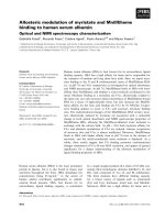
1.2.3. Poly (styrene-isobutylene-styrene) (PIBS)
The relatively new thermoplastic elastomer (TPE) Poly(styrene-isobutylene-styrene)
(PIBS) is a tri-block copolymer consisting of a polyisobutylene inner segment connected to two
polystyrene outer segments. These kinds of phase segregated polymers can exhibit unique
chemical and physical properties that be used for many applications because the distinct phases
can be tailored to meet desired mechanical and chemical properties. PIBS is a 3-phase copolymer
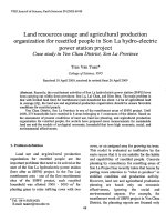
that has a three block chain arranged in an S-B-S series (Figure 2). The major component of the
PIBS copolymer is polyisobutylene, which accounts for 70-85% by weight of the base polymer.
The polyisobutylene is the soft segment of the copolymer and gives the material flexibility as
well as its low permeability. The polystyrene segment normally compromises 15-30% by weight
and forms a hard, glassy region that provides its mechanical strength. In the solid state, the
thermodynamic immiscibility of the two components results in a micro-phase separation where
domains of polystyrene are formed in the rubber polyisobutylene matrix.
13,15,16
Figure 2. Segments of the Poly(styrene-isobutylene-styrene) Tri-Block Copolymer
14
The emergence of living carbocationic polymerization provided the simplest and most
convenient method for the preparation of block copolymers by sequential monomer addition.
PIBS is created by this method, which is a chain polymerization process that proceeds in the
7
absence of chain transfer to monomer and irreversible termination. The irreversibility or
termination is emphasized, because in contrast to conventional living anionic polymerizations, in
living cationic polymerizations the concentration of the cations is very small.
17
The nature,
activities, and concentration of the active species in cationic polymerization is determined by the
mechanisms of initiation, which will determine the head and end groups. Organic esters, halides,
ethers, and alcohols have been used to initiate living polymerization of isobutylene. The
synthesis of PIBS involves sequential monomer addition using di- or trifunctional initiator in
conjunction with TiCl
4
in moderately polar solvent mixture at low temperatures.
17
PIBS has good low and high temperature properties with a maximum service temperature of
65ºC and a minimum service temperature of -50ºC. It has good aging resistance, resistance to
chemical agents, and good electrical insulating properties. Preliminary environmental tests
indicated that polyisobutylene based materials exhibit improved hydrolytic stability and reduced
moisture permeability compared to polyether and polyester polyurethanes.
They also have been
shown to exhibit greater oxidative stability compared to polybutadiene based materials, but
because of the aromatic ring containing structure of polystyrene, PIBS may be oxidizable.
The PIBS elastomer used in this study is SIBSTAR® manufactured by Kaneka Corp.
This material has the opportunity to be successful as a lead insulation material because of its
abrasion resistance, flexibility, low gas permeability, and biostability. SIBSTAR® is available in
a few different variations of molecular weight and wt% of styrene, but this study focuses on
SIBSTAR® 73T, which has a molecular weight of 65,000 and a styrene 30wt% styrene content
(Table 2).
14
8
Table 2 - Properties Comparison of SIBSTAR® Grades.
18
1.2.4. PIBS Blends – Polypropylene (PP)
Polypropylene provides excellent resistance to organic solvents and electrolytic attack. It
has a relatively low impact strength, but adequate operational temperatures and tensile strength.
It is also light in weight and has a low moisture absorption rate. It has excellent resistance to
acids and alkalines, but poor resistance to aromatic, aliphatic and chlorinated solvents. When
blended with PIBS, Poly(isobutylene-propylene) can utilize the superior mechanical and chemical
properties of both blocks of the copolymer.
1.2.5. PIBS Blends – Polyurethane (PU)
Polyisobutylene based polyurethanes belong to the class of elastomeric PUs. The reason
for interest in PIB based PUs is to make up for certain material deficiencies in pure
polyurethanes. Major weaknesses of conventional polyester and polyether based PUs are low
acid, base, hydrolytic, steam, and environmental stability and a maximum service temperature of
9
only about 105ºC. It is anticipated that PUs prepared from hydroxyl terminated PIBS will
alleviate these deficiencies.
19
1.2.6. Silicone Adhesive
In cardiac rhythm management devices, silicone (polysiloxane) adhesives are
frequently used as sealants around the connection of a lead to the pulse generator. Silicone
adhesives cure without the application of heat or pressure to form permanently flexible silicone
rubber. They usually come in one-part or two-part systems; one-part systems being the least
expensive, no mixing, ready to use, and two-part systems requiring no moisture to cure.
Adhesion relies on mainly mechanical and chemical mechanisms to form a bond between two
materials. The cure system consists of hydroxyl-terminated polymers, alkyltriacetoxysilane
cross-linkers, and a catalyst that begin cross-linking by condensation once the system comes in
contact with moisture, usually from humidity in the ambient air. A byproduct of the condensation
reaction is acetic acid, which cannot be controlled through process additives or substitutes, but
does not typically cause any negative affects. Complete cure time depends on silicone thickness
and relative humidity. The high elastomeric property of silicone adhesives gives them the ability
to absorb movement. This allows silicone adhesives to be used in applications where the
adhesive is required to absorb movements of the joint without tearing apart from the
substrate.
20,4,21
The silicone adhesive used in this study is Med-2000, which is manufactured by Nusil
Technology in Carpinteria, CA. According to the product profile from Nusil, Med-2000
improves the adhesion of addition-cured systems and two-component silicone rubbers to various
substrates including: metals (such as stainless steel, steel, copper, and aluminum), ceramics, rigid
plastics, and other silicone materials.
22
Med-2000 has not been previously defined for use with
PIBS or any PIBS blends. The manufacturer states that curing or vulcanization time depends
10
upon the thickness of the silicone adhesive layer, relative humidity, and accessibility of
atmospheric moisture to the curing adhesive. For sections of typical thickness, a relative
humidity level between 20-60% is recommended to cure the adhesive at room temperature.
Generally the adhesive forms a thick, tack-free outer skin for thick section films within a few
minutes after application. The vulcanization rate slows when exposing very thin films to
excessive humidity (≥ 80% relative humidity). For films below 80 microns, the relative air
humidity should be within 30-50%. Table 3 shows some typical properties of Med-2000.
Table 3 - Typical Properties of the Nusil Med-2000 Silicone Adhesive
22
1.2.7. Primer
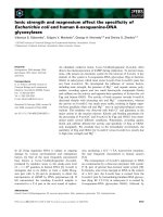
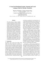
Silane primers chemically functionalize the bonding surface to provide pathways for
chemical bonding with a selected silicone cure system, which promote adhesion between two
non-bonding surfaces (Figure 3). The primers usually consist of one or more reactive silanes, a
condensation catalyst, and a solvent carrier. The silanes usually have two different reactive
groups such as a hydrophilic silanol (Si-OH) or a hydrophobic 1-octenyl group. These groups
form the two different surfaces the ability to bond with one another. The silanes and the
condensation catalyst, upon exposure to ambient humidity, form a thin polymeric film on the
bonding surface. The catalyst promotes cross-linking of the adhesive and bonding to the primer
11
film layers. It is important to avoid an overly primed surface that form a chalky film and can be a
point of bond failure.
23
Figure 3. Silane Primer Adhesion Promotion
The primer used in this study is SP-135 High Technology Silicone Primer (Clear) and is
also manufactured by Nusil Technology. SP-135 is a specially formulated, clear primer, designed
for use with platinum-cured silicone systems. According to the Nusil product profile, it improves
the adhesion of addition-cured systems and two-component silicone rubbers to various substrates
including: metals (such as stainless steel, steel, copper and aluminum), ceramics, rigid plastics,
and other silicone materials. Typical properties of Nusil SP-135 Silane Primer are shown in
Table 4.
24
Table 4 - Typical Properties of the Nusil SP-135 Silane Primer
24
12
1.3. Degradation of Polymers
Degradation characteristics of polymers are important to discuss because a large portion
of this study serves to characterize the degradation of selected PIBS based polymers in
comparison to a commonly used control (silicone). Polymers that are biologically degradable
contain functional groups that promote enzymatic hydrolysis and oxidation.
1.3.1. Environment of the Human Body
By definition, biodegradation is the chemical breakdown of materials by the action of
living organisms that lead to change in physical properties. On the surface it seems that the
neutral pH level, mild temperature, and low salt content of the body would provide a non-
corrosive environment, but in reality there are many unique mechanisms that act on an
implantable medical device. Post-implantation, both absorption and adsorption occur when
cellular components in the body’s organic fluid attach to the surface and diffuse into the bulk of a
material. These cellular components initiate the chemical processes that lead to biodegradation.
4
1.3.2. Hydrolysis
Hydrolysis is defined as the scission of vulnerable functional groups by reaction with
water, which may be catalyzed by acids, bases, salts, or enzymes.
4
The most susceptible
functional groups include esters, amides, and carbonates. Because hydrolysis results in chain
cleavage, the physical properties of the material can be affected through a negative change in
molecular weight. Ion-catalyzed hydrolysis is the most likely cause of degradation in medical
implants using hydrolysable polymers. Bodily fluids contain the common ions H
+
, OH
-
, Na
+
, Cl
-
,
HCO
3
-
, K
+
, Mg
2+
, and Ca
2+
, which are all effective hydrolysis catalysts. In addition to the
hydrolytic catalysts, localized pH changes in the vicinity of an implanted device due to
13
inflammation or infection can cause an increase in the rate of hydrolysis.
4
The PIBS structure is
composed of alkyl blocks, which are highly resistant to hydrolytic degradation.
1.3.3. Oxidation
There are several different modes of oxidation, which include autooxidation, oxidation by
peroxides, free radicals, enzymes, and metal-ion oxidation. The functional groups most
susceptible to oxidation include ethers, aromatics, phenols, alcohols, amines, and aldehydes.
Failure of polymers used for pacemaker lead insulation typically occurs from two mechanisms:
environmental stress cracking (ESC) and metal ion oxidation (MIO). ESC occurs from direct
contact with human tissue and MIO from direct contact with the lead conductor coils.
Environmental stress cracking is characterized by deep, ragged fractures within the material, most
often perpendicular to the applied stress. The MIO mechanism involves interaction between the
metal of the conductor coil and hydrogen peroxide. In the case of pacemaker leads, hydrogen
peroxide, a known product of inflammatory cells involved in the foreign body response.
Oxidation of a polymer usually leads to increased brittleness, reduced strength, and a yellowing in
color.
25
14
2. PURPOSE AND EXECUTION OF STUDY
In order to take advantage of the properties of PIBS and PIB based blends as lead
insulation materials, they must be able to sufficiently bond to the various materials that make up
the cardiac device. The bonded PIBS must be able to withstand the mechanical stress and
corrosive environment of the human body due to the long term use of these devices. Although
silicone, one of the commonly used lead insulation materials, provides excellent resistance to
biodegradation, it also possesses multiple drawbacks due to its relative softness. First, its softness
can cause it to be prone to damage from abrasion upon implantation. Because of its relatively
low tear strength, silicone lead insulation poses a major design restraint in moving toward the
trend of smaller diameter pacing leads. The final disadvantage of silicone is its high coefficient
of friction, which can lead to thrombosis.
28
Based on the component requirements of lead insulation, the first objective of this study
is to perform an initial screening of multiple poly(styrene-isobutylene-styrene) / stainless steel /
silicone adhesive combinations. Based on the bonding shear strength results of the initial
screening, the best performing combinations will be artificially aged to simulate their resistance
to degradation in vivo. The combination that exhibits the best resistance to biodegradation can be
considered the most ideal candidate for use as a lead insulation material.
2.1. Phase I: Initial Screening
2.1.1. Objective and Deliverables
The Phase I objective is to get initial silicone bond shear strength data for multiple PIBS
blends compared to a control (silicone tubing). Based on the collected data, samples will be
selected for further investigation in Phase II of this study.
15
Phase I deliverables include:
• Raw data for silicone bond shear strength for PIBS blends to stainless steel and Silicone
(control) to stainless steel.
• Statistical analysis of data to significance in difference between bond shear strengths of
all combinations.
• Combinations selected for Phase II
2.1.2. Materials and Equipment
Below is a list of all materials and equipment required for Phase I of this study:
Materials
• Adhesive: Nusil MED-2000 Silicone
• Primer: Nusil SP-135 Silane Primer
• PIBS Blends:
- SILASTIC Q7-4780 Silicone tubing
- SIBSTAR Poly(styrene-isobutylene-styrene) tubing (PIBS)
- PIBS / 10%PP
- PIBS / 10%55D Polyurethane
- PIBS / 10%75D Polyurethane
• Bonding Substrate: EFD Stainless Steel Precision Tips 5118-B
Equipment
• Tensile Tester: Chatillon
• Load Cell: 11 lb
• Small Tip Camel Hair Brush
2.1.3. Procedure and Methodology
The following is the standard procedure used to produce and test samples including a justification
of the method in italics where appropriate:
16
1. General Setup
1.1. Clean surface and remove any unnecessary materials and equipment.
2. Cut and Label Samples
2.1. Using a clean razor blade, cut six, three inch long pieces of tubing for each
sample group.
NOTE: Ensure that the cuts are made straight so that the tubing face is
perpendicular to ground.
Cuts must be straight to keep the bonding surface area consistent between samples.
2.2. Label trays with each sample group name and store samples in the
appropriate tray.
3. Apply Primer
3.1. Using a small tip camel hair brush, apply a thin layer of primer to the inside
diameter of each tube of the six tubes in one group approximately 4 mm
deep.
NOTE: If primer dries to a whitish or chalky appearance, the coating is too
thick. Discard and replace the tube and reapply primer with a thinner layer.
A small tipped brush was used to apply the primer due to its relatively low
viscosity.
3.2. Record the time and date of primer application.
3.3. Repeat for each sample group.
3.4. Allow primer to dry for 1 hour at room temperature before proceeding to step
4.
Nusil’s product profile suggests a dry time of 30 minutes at room temperature, but to
ensure a complete curing, a dry time of 1 hour at room temperature was used for this
study.
4. Apply Silicone Adhesive
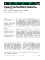
4.1. Using Figure 4 as a reference to replicate the amount of adhesive, insert the
tip of an EFD Stainless Steel Tip into the MED-2000 Silicone Adhesive so
that a small amount of adhesive remains on the tip after removal.
Figure 4. Adhesive quantity reference.
This method is considered to have a large potential to produce variance in the
output. An ideal method, perhaps using a time and pressure controlled dispensing
system, would precisely control the amount of adhesive used for bonding.
4.2. With a target depth of 2mm, insert the stainless steel tip into the polymer
tubing.
NOTE: Do not retract the SS tip after reaching the desired insertion depth.
Adhesive
SS Tip
17
4.3. Gently wipe any excess adhesive on the SS tip above the tubing with a lint-
free cloth.
To truly observe the bond shear strength between the needle and tubing it was
important to ensure that the adhesive did not extend outside of the ideal bonding area
(i.e. adhesive beyond the needle inside of the tube, or above the tube on the needle
surface). This method minimized variation in bond shear strength due to adhesive
application. Due to the difficulty of consistently inserting the needle to a depth of
2mm, the actual insertion depth was measured prior to pull testing.
4.4. Twist the needle clockwise, then counter-clockwise 180º in each direction to
ensure adhesive covers the entire bonding surface.
4.5. Record time and date of bonding.
4.6. Repeat for all samples in each sample group.
There were 6 replicates for 5 sample groups for a total of 30 samples.
4.7. Allow adhesive to cure for 72 hours before continuing to step 5.
5. Tensile Test
5.1. Measure the bond length of each sample using a pair of calipers.
5.2. Using the cutting surface of a pair of pliers, clip the plastic connector from
each SS tip.
NOTE: Use care to not disrupt the bond during removal of connector.
5.3. Place the SS tip into the lower clamp and the tubing end into the upper
5.4. Using a gauge length of 2” and a pull speed of 1mm/sec, perform a tensile
test one the samples from each sample group (Figure 5).
NOTE: Ensure that the sample is aligned vertically between the upper and
lower clamps.
Figure 5. Lloyd LF Plus Tensile Tester with Grippers
18
5.5. Record tensile strength for each sample and whether the sample failed at the
tube or at the bond.
6. Calculate Bonding Shear Strength
6.1. Use Hooke’s Law (1) to calculate the shear strength (
τ
), where:
A
P
=
τ
(1)
P = Maximum Load
A = Bond Area
The bond area was calculated using the measured SS tip insertion depth (d) and
outer diameter (1.26 mm): drA
×
=
π
2 . Bond shear strength is the critical output
of Phase I.
7. Statistical Analysis
7.1. Calculate descriptive statistics (mean, standard deviation, min, max, etc).
7.2. Perform two-sample t-tests with a 95% confidence level for each sample
group against all others to determine if there is a significant difference
between them.
2.2. Phase II: Aging Stability
2.2.1. Objectives and Deliverables
For a lead insulation to be effective, it must withstand the harsh environment of the
human body for an extended period of time. Phase II of this study served to simulate the
hydrolytic and oxidative instability of the PIBS blends through artificial aging. Because of the
interest in observing the aging characteristics of all sample groups, the decision was made to use
all materials for the second phase of this study.
2.2.2. Materials and Equipment
The following is a list of materials and equipment used during Phase II of this study:
Materials
• Adhesive: Nusil MED-2000 Silicone
• Primer: Nusil SP-135 Silane Primer
• PIBS Blends:
- SILASTIC Q7-4780 Silicone tubing
- SIBSTAR Poly(styrene-isobutylene-styrene) tubing (PIBS)