Hindawi Publishing Corporation EURASIP Journal on Audio, Speech, and Music Processing Volume 2010, pptx
Bạn đang xem bản rút gọn của tài liệu. Xem và tải ngay bản đầy đủ của tài liệu tại đây (5.11 MB, 13 trang )
Hindawi Publishing Corporation
EURASIP Journal on Audio, Speech, and Music Processing
Volume 2010, Article ID 252374, 13 pages
doi:10.1155/2010/252374
Research Ar ticle
Monaural Voiced Speech Segregation Based on
Dynamic Harmonic Function
Xueliang Zhang,
1, 2
We nj u Li u,
1
and Bo Xu
1
1
National Laboratory of Pattern Recognition (NLPR), Institute of Automation, Chinese Academy of Sciences, Beijing 100190, China
2
Computer Science Department, Inner Mongolia University, Huhhot 010021, China
Correspondence should be addressed to Wenju Liu,
Received 17 September 2010; Accepted 2 December 2010
Academic Editor: DeLiang Wang
Copyright © 2010 Xueliang Zhang et al. This is an open access ar ticle distributed under the Creative Commons Attribution
License, which permits unrestricted use, distribution, and reproduction in any medium, provided the original work is properly
cited.
Correlogram is an important representation for periodic signals. It is widely used in pitch estimation and source separation. For
these applications, major problems of correlogram are its low resolution and redundant information. This paper proposes a v oiced
speech segregation system based on a newly introduced concept called dynamic harmonic function (DHF). In the proposed system,
conventional correlograms are further processed by replacing the autocorrelation function (ACF) with DHF. The advantages of
DHF are: 1) peak’s width is adjustable by controlling the variance of the Gaussian function and 2) the invalid peaks of ACF, not at
the pitch period, tend to be suppressed. Based on DHF, pitch detection and effective source segregation algorithms are proposed.
Our system is systematically evaluated and compared w ith the correlogram-based system. Both the sig nal-to-noise ratio results
and the perceptual evaluation of speech quality scores show that the proposed system yields substantially better performance.
1. Introduction
In realistic environment, speech is often corrupted by acous-
tic interference. Meanwhile, many applications have bad per-
formance when handling the noisy speech. Therefore, noise
reduction or speech enhancement is meaningful for systems
such as speech recognition and hearing aids. Numerous
speech enhancement algorithms have been proposed in the
literature [1]. The methods, such as independent component
analysis [2]orbeamforming[3], require multiple sensors.
However, this requirement is not applicable for many
applications such as telecommunication. Spectrum subtrac-
tion [4] and subspace analysis [5] proposed for monaural
speech enhancement usually make strong assumptions on
acoustic interference. Therefore, these methods are limited
to some special environments. Segregating speech from one
monaural recording has proven to be very challenging. At
present, it is still an open problem in realistic environments.
Compared with the limited performance of speech
enhancement algorithms, human listeners with normal
hearing are capable of dealing with sound intrusions, even in
monaural condition. According to Bregman [6], a human’s
auditory system segregates a target sound from interference
through a process called auditory scene analysis (ASA)
which has two parts: (1) sound signal decomposition and
(2) components grouping. Bregman considered that the
components organization included sequential organization
on time series and simultaneous organization on frequency
series. To simulate ASA inspired a novel field, computational
auditory scene analysis (CASA) [7], which has obtained more
and more attention. Compared with other general methods,
CASA can be applied under single channel input, and it has
no strong assumption on the prior knowledge of noise.
A large proportion of sounds have harmonic structure,
such as vowels and music tone. The most distinct character-
istic is that these sounds consist of fundamental harmonic
(F0) and several overtones which are called harmonic series.
A good deal of evidence suggest that harmonics tend
to be perceived as a single sound. The phenomenon is
called the “harmonicity” principle in ASA. Pitch and har-
monic structure provide an efficient mechanism for voiced
speech segregation in CASA systems [8, 9]. Continuous
variation of pitch is good for sequential grouping, and
harmonic structure is suitable for simultaneous grouping.
2 EURASIP Journal on Audio, Speech, and Music Processing
Case A
Case B
0Hz
300 Hz
600 Hz
900 Hz
400 Hz
600 Hz
800 Hz
1000 Hz
200 Hz
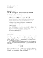
Figure 1: Frequency component perception.
Licklider [ 10] proposed that pitch could be extracted from
nerve firing patterns by a running autocorrelation function
performed on the activity of individual fibers. Licklider’s the-
ory was implemented by the scholars (e.g ., [11–14]). Meddis
and Hewitt [14] implemented a similar computer model
for harmonics perception. Specifically, their model firstly
simulated the mechanical filtering of basilar membrane to
decompose the signal and thenthemechanismofneural
transduction at hair cell. Their important innovation was
to conduct the autocorrelation to model the neural firing
rate analysis of human being. These banks of autocorrelation
functions (ACF) were called correlograms which provide
a simple way to pitch estimation and source separation.
For pitch estimation, previous research [14] showed that
peaks of summary correlograms indicate the pitch periods.
According to the experiment results, Meddis and Hewitt
argued that many phenomena about pitch perception could
be explained with their model including the missing fun-
damental, ambiguous pitch, the pitch of interrupted noise,
inharmonic components, and the dominant region of pitch.
For source separation, the method as in [15]istodirectly
check that whether th e pitch period is close to the peak
of correlograms. By t hese advantages of correlogram, it is
widely used in pitch detection [16] and speech separation
algorithms [8 , 9, 15].
However, there are some unsatisfactory facts. One was
pointed out that the peak corresponding to the pitch period
forapuretoneisratherwide[17]. It leads to low resolution
for the pitch extraction since mutual overlap between voices
weakens their pitch cues. Some methods were proposed to
obtain narrow peaks, such as “narrowed” ACF [18]and
generalized correlation function [ 19]. Another problem is
redundant information caused by the “invalid” peaks of
ACF.Infact,wecaremoreaboutthepeakofACFatthe
pitch period when using correlogram to estimate pitch and
separate sound sources. For example, algorithm [14]used
the maximum peak of summary correlogram to indicate the
pitch period. However, competitive peaks at multiples of
pitch p eriod may leads to subharmonic errors. To overcome
the drawbacks, the first thing is to make the peaks narrower,
and the second is to remove or suppress the peaks which are
not at the pitch periods. We propose a novel feature called
dynamic harmonic function to solve these two problems. The
basic idea of DHF is shown in the next section.
The rest of the paper is organized as follows. We firstly
present the basic idea b ehind DHF in Section 2. Section 3
gives an overview of our model and specific d escription. Our
system is systematically evaluated and compared with the
Hu and Wang model for speech segregation in Section 4,
followed by the discussion in Section 5 and the conclusion
in Section 6.
2. Basic Idea of DHF
DHF is defined as a Gaussian mixture function. Gaussian
means equal to the peak position of ACF which carries
periodic information about the original signal in a certain
frequency range. The peak width can be narrowed by
adjusting the Gaussian variance. Meanwhile, the Gaussian
mixture coefficient controls the peak height of DHF. The
problem is how to estimate the mixture coefficients. The
basic idea is as follows.
Voiced speech generally has a harmonic structure includ-
ing continuously numbered harmonics. Therefore, one could
verify a pitch hypothesis based on whether or not there is
a continuously numbered harmonics corresponding to this
pitch. For example, when its neighbor harmonics appear at
400 Hz or 800 Hz, harmonic at 600 Hz is regarded as the
third harmonic of the complex tone whose pitch is 200 Hz,
such as case A in Figure 1. In this case, the pitch period is at
the third peak position of ACF of frequency region around
600 Hz. While in case B, the pitch period is at the second
peak position. Based on this idea, Gaussian mixture function
tends to give a high peak at a p itch period hypothesis if
its neighbor harmonics appear. It implies that the shape
of guassian mixture function of a harmonic does not only
depend on the frequency of harmonic itself but also the
neighbor harmonics around. Therefore, we call it dynamic
harmonic function.
3. System Overview
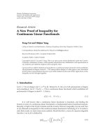
The proposed model contains six modules shown in Figure 2.
In fr ont-end processing stage, signal is decomposed into
small units along time and frequency. Each unit is called
T-F unit. After that, the features of each unit are extracted,
such as normalized ACF, normalized envelope ACF proposed
in previous studies [16], and newly introduced carrier to
envelope energy ratio. In the second stage, DHF in each
unit is computed. According to different characteristic, the
units are first classified into two categories: (1) resolved T-F
unit dominated by a single harmonic and (2) unresolved T-F
unit dominated by multiple harmonics. The computations of
DHF for resolved and unresolved T-F unit are different. More
details can be seen in Section 3.2. In the pitch estimation
stage, pitch of target speech is extracted based on DHFs.
Before that, the resolved T-F units are merged into segments
EURASIP Journal on Audio, Speech, and Music Processing 3
Input mixture
Front-end
processing
Dynamic
harmonic
function
Pitch
estimation
Unit
labeling
Segment
segregation
Resynthesis Segregated
speech
Figure 2: Schematic diagram of the proposed multistage system.
95
105 115 125 135 145 155
Times (ms)
(a)
0 2.5 5 7.5 10 12.5
Delay (ms)
(b)
0 2.5 5 7.5 10
12.5
Delay (ms)
(c)
0 2.5 5 7.5 10 12.5
Delay (ms)
(d)
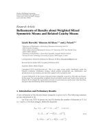
Figure 3: (a) is channel response dominated by multiple harmon-
ics; (b) is the ACF of the channel; (c) is the envelope ACF of the
channel; (d) is the “enhanced” envelope ACF of the channel and the
vertical line in (d) is the corresponding pitch period.
firstly. Segmentation has been performed in previous CASA
systems. A segment is a larger component of an auditory
scene than a T-F unit and captures an acoustic component
of a single source. An auditor y segment is composed of a
spatially continuous region of T-F units. Therefore, compu-
tational segment is formed according to time continuity and
cross-channel correlation. It is reasonable to expect that high
correlation shows the adjacent channels dominated by same
source. However, frequencies of target and intrusion are
often overlapped and it leads to the computational segments
being dominated by different sources. In our model, we
expect a segment to be dominated by the same harmonic of
the same source. Hence, we employed another unit feature
called harmonic order to split the segments into relative small
ones. Its benefit is shown in following subsection. Harmonic
order represents the unit dominated by which harmonic
of the sound. During the unit labeling stage, T-F unit is
1.61 1.62 1.63 1.64
1.65
Time (s)
(a)
1.61 1.62 1.63 1.64
1.65
Time (s)
(b)
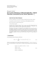
Figure 4: Filter response (the solid line) and its envelope (the
dash line). (a) At channel 20 with center frequency 242 Hz. (b) At
channel 100 with center frequency 2573 Hz.
labeled as target or intrusion according to the estimated pitch
and DHF. In the fifth stage, T-F units are segregated into
foreground and background based on segmentation. Finally,
the T-F units in foreground synthesize the separated speech.
3.1. Front-End Processing
3.1.1. Signal Decomposition. At first, an input signal is de-
composed by 128-channel gammatone filterbank [20]whose
center frequencies are quasilogarithmically spaced from
80 Hz to 5 kHz and bandwidths are set according to
equivalent rectangle bandwidth (ERB). The gammatone
filterbank simulates the characteristic of basilar membrane
of the cochlea. Then, the outputs of filterbank are transited
into neural firing rate by hair cell model [21]. The same
processing is employed in [9, 15]. Amplitude modulation
(AM) is important for channels dominated by multiple
harmonics. Psychoacoustic experiments have d emonstrated
that amplitude modulation or beat rate is perceived in a
critical band within which harmonic partials are unr esolved
[6]. The AM in channels are obtained by performing
Hilbert transform on gammatone filter output and then
4 EURASIP Journal on Audio, Speech, and Music Processing
0
2.5 5 7.5 10 12.5
−1
0
1
Delay (ms)
(a)
−1
0
1
0
2.5 5 7.5 10 12.5
Delay (ms)
(b)
−1
0
1
0
2.5 5 7.5 10 12.5
Delay (ms)
(c)
1
0
0
2.5 5 7.5 10 12.5
Delay (ms)
(d)
Figure 5: (a) ACF at channel 10 whose center frequency (cf) is 148
Hz; (b) ACF at channel 30 w hose cf is 360 Hz; (c) ACF at channel
45 whose cf is 612 Hz; (d) enhanced envelope ACF at channel 100
whose cf is 2573 Hz; Input signal is a complex tone with F0
= 200
Hz; The vertical dash line shows the pitch period.
by filtering the squared Hilbert envelope by a filter with
passband (50 Hz, 550 Hz). In the following par t, gammatone
filter output, hair cell output, and amplitude modulation
at channel c are represented by g(c,
·), h(c, ·), and e (c, ·),
respectively .
Then, time frequency (T-F) units are formed with 10 ms
offset and 20 ms window in each channel. Let u
cm
denote
a T-F unit for frequency channel c and time frame m.The
T-F units will be segregated into foreground and background
according to their features.
3.1.2. Feature Extraction. Previous researches have shown
that the correlogram is an effective mid-level auditory repre-
sentation for pitch estimation and source segregation. Thus,
the normalized correlogram and the normalized envelope
correlogram are computed here. For T-F unit u
cm
,theyare
computed as the following equations which are same as in
[16]:
A
H
(
c, m, τ
)
=
W
n
=0
h
(
c, m · T + n
)
× h
(
c, m · T + n + τ
)
W
n
=0
h
2
(
c, m
· T + n
)
W
n
=0
h
2
(
c, m
· T + n + τ
)
(1)
A
E
(
c, m, τ
)
=
W
n
=0
e
(
c, m · T + n
)
× e
(
c, m · T + n + τ
)
W
n
=0
e
2
(
c, m
· T + n
)
W
n
=0
e
2
(
c, m
· T + n + τ
)
,
(2)
where lag τ
∈ [0, 12.5ms], shift T = 160 corresponds to
10 ms and window length W
= 320.
One knows that the peak position of ACF reflects the
period or its multiple of the signal. A
H
is a proper feature
to segregate the T-F units dominated by a single harmonic.
However, it is not suitable for the T-F units dominated
by several harmonics because of the peaks’ fluctuation, as
shown in Figure 3(b).Inthiscase,A
E
is employed for
segregation whose first peak position usually corresponds
to pitch period. In order to remove the peaks at integer
multiples of the pitch period, the normalized envelope ACF
is further processed into “enhanced” envelope ACF as shown
in Figure 3(d). Specifically, A
E
(c,m, τ)ishalfrectifiedand
expended in time by fa ctor N and subtracted from clipped
A
E
(c,m, τ), and again, the result is half rectified. Iteration
is performed by N
= 1 ···6 to c ancel spurious peaks in
possible pitch range. The computation is similar with the one
in [22].
Since we use different features to seg regate the T-F units
dominated by a single harmonic and the ones dominated by
several harmonics, it is important to classify the T -F units
correctly according to their different characteristics. In order
to narrate facility, we define the resolved T-F unit as the
one dominated by a single harmonic and the unresolved T-F
unit as the one dominated by multiple harmonics. In fact,
the fluctuation of envelope is relative severe in unresolved
T-F units because of the amplitude modulation. Figure 4
shows the filter response and its envelope in resolved T-F
unit (Figure 4(a)) and in unresolved T-F unit (Figure 4(b)).
Here, a feature—carrier to envelope energy ratio, proposed
in our previous work [23], is employed to classify the units
into resolved and unresolved ones. If the R
eng
is larger
than a threshold, the T-F unit is regarded as resolved one
and vice versa. For T-F unit u
cm
, its computation is given
by
R
eng
(
c, m
)
= log
W
t
=0
g
(
c, T · m + t
)
2
W
t
=0
e
(
c, T · m + t
)
2
. (3)
In a unit u
cm
, severe fluctuation of envelope leads to
R
eng
(c,m) being small. Hence, we regard u
cm
as unresolved
if R
eng
(c, m) <θ
R
or else as resolved. Here, the θ
R
= 1.8
according to the experiments.
As demonstrated in [15], cross-channel correlation
measures the similarity between the responses of two
adjacent filter channels and indicates whether the filters
are responding to the same sound component or not.
It is important for subsequent segmentation. Hence, the
cross-channel correlation and cross-channel correlation of
envelopes are calculated as
C
H
(
c, m
)
=
L−1
τ=0
A
H
(
c, m, τ
)
×
A
H
(
c +1,m, τ
)
,(4)
EURASIP Journal on Audio, Speech, and Music Processing 5
Frequency (Hz)
5000
2335
1028
387
80
Delay (ms)
0 2.5 5 7.5 10 12.5
(a)
Frequency (Hz)
5000
2335
1028
387
80
Delay (ms)
0 2.5 5 7.5 10 12.5
(b)
Figure 6: Auditory features. The input signal is complex tone with F0 = 200 Hz. (a) correlogram at frame m = 120 for the clean female
speech (channel 1–80 is ACFs, channel 81–128 is envelope ACFs). The summary correlogram is shown in bottom panel; (b) corresponding
dynamic harmonic functions. The summary dynamic harmonic function is shown in bottom panel. The variance of DHF σ is 2.0.
Delay (ms)
12.5
10
7.5
5
2.5
0
Time (s)
0 0.4 0.8 1.2 1.6
(a)
Delay (ms)
12.5
10
7.5
5
2.5
0
Time (s)
0
0.4 0.8
1.2 1.6
(b)
Figure 7: x-axis is frame, y-axis is lag; (a) Conventional periodogram (channel 1–80 is ACF, channel 81–128 is envelope ACF); (b) Dynamic
harmonic function periodogram. The input signal is male speech mixed w ith female speech.
C
E
(
c, m
)
=
L−1
τ=0
A
E
(
c, m, τ
)
×
A
E
(
c +1,m, τ
)
,(5)
where,
A
H
(c, m, ·)and
A
E
(c, m, ·) are zero-mean and unity-
variance versions of A
H
(c, m, ·)andA
E
(c, m, ·).
3.2. Dynamic Harmonic Function. DHF is defined by a one-
dimensional Gaussian mixture function as in formula (6)
which indicates the probability of lag τ being the pitch
period. We intend to use the variances of Gaussian function
to narrow the peaks’ width and the mixture coefficients
6 EURASIP Journal on Audio, Speech, and Music Processing
Channel
128
96
64
32
1
Frame
0 40 80 120 160
(a)
Channel
128
96
64
32
1
Frame
0 40 80 120 160
(b)
Figure 8: S egmentation comparison. The input signal i s a voiced speech mixed by click noise. (a) Segments formed by cross-channel
correlation and time continuity. The black region is dominated by speech and the gray region is dominated by click noise. (b) Segments
formed by cross-channel correlation, time continuity and carrier -to-env elope energy ratio.
12.5
10
7.5
5
2.5
0
Time (s)
0 0.2 0.4 0.6 0.8 1 1.2 1.4
Lag (ms)
(a)
12.5
10
7.5
5
2.5
0
Time (s)
0 0.2 0.4 0.6 0.8 1 1.2 1.4
Lag (ms)
True pitch
Estimated pitch
(b)
Figure 9: Result of pitch for the mixture of speech and cocktail party. (a) Summary of dynamic harmonic function (only with the peak
corresponding to harmonic order) within longest segment. (b) Estimated pitch contour, marked by “o” and the solid line is the pitch contour
obtained from clean speech before mixing.
EURASIP Journal on Audio, Speech, and Music Processing 7
0 0.3 0.6 0.9 1.2 1.5 1.8
Time (s)
(a)
0 0.3 0.6 0.9 1.2 1.5 1.8
Time (s)
(b)
0 0.3
0.6 0.9 1.2 1.5 1.8
Time (s)
(c)
Figure 10: Waveforms. (a) clean speech; (b) mixture of clean speech
and cocktail party noise; (c) segregated speech by the proposed
method.
to suppress the “invalid” peaks. In the following part, we
show how to calculate the parameters of DHF. Although
the representations of DHF are identical, calculations of the
parameters are different for resolved and unresolved units
D
(
c, m, τ
)
=
N
p
n=1
λ
(
c, m, n
)
· gau
τ;μ
(
c, m, n
)
, σ
2
,
(6)
gau
τ;μ, σ
2
=
exp
−
τ − μ
2
2σ
2
,
(7)
where, lag τ
∈ [0, 12.5 ms] (same as in ACF); N
p
is the
number of peaks of ACF.
In formula (6), there are four parameters component
number, Gaussian means, Gaussian variances, and Gaussian
mixture coefficients to be computed. The component num-
berequalstothenumberofpeaksofACF.Meanofthenth
Gaussian function is set to the position of the nth peak of
ACF. Gaussian variances are used to control the peak width
of DHF which are determined later. The following part will
show the estimation method of the mixture coefficients.
For the DHF of a T-F unit, we want to give a higher peak
at the pitch period if it is dominated by voiced sound, which
means a l arger mix ture coefficient for the corresponding
Gaussian function. Therefore, our work is to estimated pitch
period at each T-F unit. Let us see an example at first. The
input signal is a complex tone with F0
= 200 Hz and all the
amplitude of harmonics are equal. Figures 5(a)–5(c) show
the ACFs of correlogram at channel 10, 30 and 45 with center
frequency 148 Hz, 360 Hz, and 612 Hz, respectively. And
Figure 5(d) shows the enhanced envelope ACF at channel
100 with center frequency 2573 Hz. Obviously, channel 30
is dominated by the second harmonic of complex tone.
However, it is not indicated by ACF because its peaks
have equal amplitude. In fact, without information of the
other channels, there are several interpretations for channel
30 according to ACF. For example, the channel could be
dominated by the second harmonic where F0
= 400 Hz or
by forth harmonic where F0
= 100 Hz. In DHF, we expect
that the second mixture coefficient of DHF could be larger
than others. Analysis above implies that the computation
of mixture coefficient has to combine the information of
other channels. According to analysis above, the mixture
coefficient of DHF for resolved T-F unit u
cm
is computed as
follows:
p
e
(
c, m, n, τ
)
= exp
−
τ − μ
(
c, m, n
)
2
2σ
2
c,m
,(8)
p
s
(
m, n, τ
)
= max
c
p
e
(
c, m, n, τ
)
,(9)
where, μ(c,m,n)isthemeanofthenth Gaussian
function; σ
c,m
= μ(c, m,1)/4.0. Formula (8)showsthe
pseudopossibility of u
cm
dominated by the nth harmonic
of the sound with pitch period at τ.And(9)showsthe
possibility of the nth harmonic with hypothesis pitch period
τ appearing at frame m
λ
(
c, m, n
)
= max
p
s
m, n − 1, μ
(
c, m, n
)
,
p
s
m, n +1,μ
(
c, m, n
)
.
(10)
Formula (10) shows that the nth mixture coefficient
depends on the appearance of the n
− 1th or n +1th
harmonic. As seen in Figure 5,thesecondmixturecoefficient
of DHF in (b) is large, because there are channels (a) and (c)
dominatedbythefirstandthethird harmonic of the complex
tone whose pitch period is 5.0 ms. While the forth m ixture
coefficient is small, because no channels were dominated by
the third or the fifth harmonic whose frequencies are 300 Hz
and 500 Hz, respectively.
From formula (8)–(10), it can be seen that a mixture
coefficient of DHF does not depend on its all related har-
monics but only two neighbours. O ne reason is to simplify
the algorithm. The other is that previous psychoacoustic
experiments [6] showed t hat the nearest related harmonics
have the strongest effect for the harmonic fusion. During
the experiments, scholars used a stimulus in which a r ich
tone with 10 harmonics wav alternated with a pure tone and
checked if the harmonic of rich tone could be captured by the
pure tone. It was found that a harmonic was easier to capture
out of the complex tone when neighboring har monics were
removed. According to the results, one of conclusions is “the
greater the frequency separation between a harmonic and its
nearest frequency neighbors, the easier it was to capture it
out of the complex tone.”
For u nresolved T-F unit, computation of the mixture
coefficients is different from resolved. One reason is that
unresolved T-F unit is dominated by several harmonics at
the same time. Hence, the peak order of its ACF does not
reflect the harmonic order accurately. Another reason is that
8 EURASIP Journal on Audio, Speech, and Music Processing
the resolution of gammatone filter is relative low in high-
frequency region and the continuously numbered harmonic-
structure cannot be found in correlograms. Fortunately, the
peak of enhanced envelope ACF tends to appear around pitch
period, as shown in Figure 5(d). It implies that the mixture
coefficient should be large if the mean of Gaussian function
is close to the peak of enhanced envelope ACF. Therefore,
the mixture coefficient equals to the amplitude of enhanced
envelope ACF at the mean of Gaussian function, as in
λ
(
c, m, n
)
=
A
E
c, m, μ
(
c, m, n
)
, (11)
where
˜
A
E
(c, m, ·) is t he enhanced envelope ACF; μ(c,m,n)is
the nth peak’s position of ACF.
In order to estimate the pitch, we also define the sum-
mary DHF at frame m as formula (12) which is important
for pitch estimation
S
(
m, τ
)
=
c
D
(
c, m, τ
)
. (12)
Figure 6 shows the comparison of correlogram and
DHFs. It can be seen that (1) peaks in DHFs are less in ACFs,
(2) the peaks at the pitch period are properly preserved,
and (3) the peaks in summary DHF are narrower than
in summary correlogram. Figure 7 shows the periodogram
(a time series of summary correlogram) comparison. The
input signal is male utterance, “where were you away a
year, Roy” mixed by a female utterance. For conventional
periodogram (a), pitch information of two sources is mixed
together and it is hard to separate directly whereas it is clear
in DHF periodog ram (b).
3.3. Pitch Estimation. Pitch estimation in noisy en vironment
is closely related to sound separation. If, on one hand, the
mixed sound is separated, the pitch of each sound can be
obtained relatively easily. On the other hand, pitch is a very
efficient grouping cue for sound separation and widely used
in previous systems [8, 9, 15]. In the Hu and Wang model,
a continuous pitch estimation method is proposed based
on correlogram in which the T-F units are merged into
segments according to cross-channel correlation and time
continuity. Each segment is expected to be dominated by
a single voiced sound. At first, they employed the longest
segment as a criterion to initially separate the segments into
foreground and background. And then, the pitch contour is
formed using units in foreground and followed by sequential
linear interpolation, more details can be found in [9].
It is obvious that initial separation plays an important
role for pitch estimation. Although result of the simple
decision could be adjusted in the following stage through
iterative estimation and linear interpolation so as to give an
acceptable prediction of pitch contour, it yet does not satisfy
the requirements of the segregation and may also deliver
some segments which are dominated by the intrusions into
the foreground. This will certainly affect the accuracy of the
result of pitch.
As a matter of fact, the pitch period is reflected by the
ACF of each harmonic. The problem is that ACF has multiple
peaks pitch estimation could be simple that if we find the
longest segment which is dominated not only by the same
source but also by the same harmonic and also know the
harmonic order. It only needs to summate the corresponding
peaks on each frame and regard the position of the maximum
peak as pitch period. This process avoids source separation
and pitch interpolation. Under the instruction of above
analysis, we try (1) to find the longest segment and (2) to
estimate the harmonic order. In this subsection, we will solve
these two problems based on DHFs.
In previous systems [9, 15], the segments are formed
by cross-channel correlation and time continuity of T-F
units. The motivation is that high-cross-channel correlations
indicate adjacent channels dominated by the same harmonic
and voiced sections have continuity on time scale. However,
some of the formed segments are dominated by different
sources or multiple harmonics. Figure 8(a) shows the seg-
ments which are generated by cross-channel correlation and
time continuity. The input signal is a voiced speech mixed
by click noise. The black region is dominated by speech and
the gray region is dominated by click noise. It is obvious
that click noise has no harmonic structure and unit at higher
channels is dominated by multiple harmonics. Hence, we
expect that each segment is dominated by a single harmonic
of the same source. Therefore, to use these segments directly
is not proper. Here, we add other two features of T-F unit for
segmentation. One is carrier-to-envelope energy ratio which
is computed by formula ( 3) and the other is unit harmonic
order.
3.3.1. Initial Segmentation. As mentioned in Section 3.2,
T-F units are classified into resolved and unr esolved by
carrier-to-envelope energy ratio. Each resolved T-F unit is
dominated by a single harmonic. In addition, because the
passbands of adjacent channels have significant overlap , a
resolved harmonic usually activates adjacent channels, which
leads to high-cross-channel correlations. Thus, only resolved
T-F units with sufficiently high-cross-channel correlations
are considered. More specifically, resolved unit u
cm
is selected
for consideration if C
H
(c, m) > 0.975, chosen to be little
lowerthanin[15]. Selected neighboring units are iteratively
merged into segments. Finally, segments shorter than 30 ms
are removed, since they unlikely arise from target speech.
Figure 8(b) shows a result of segmentation for the same
signal in Figure 8(a).
3.3.2. Harmonic Order Computation. For a resolved T-F unit
u
cm
,harmonicorderO
u
(c,m) indicates the unit d ominated
by which harmonic. Although DHF suppress some of
peaks compared with ACF, there are still multiple invalid
peaks especially at the fraction of pitch period, as seen in
Figure 6(b). We still cannot decide the harmonic order by
DHF. Fortunately, those peaks at the fractional pitch period
are suppressed in summary DHF. Hence, the computation
combines the DHF and summary DHF as
O
u
(
c, m
)
= argmax
n
λ
(
c, m, n
)
× S
m, μ
(
c, m, n
)
. (13)
EURASIP Journal on Audio, Speech, and Music Processing 9
From the above algorithm, we can see that the harmonic
order of a resolved unit depends on single frame. Due to the
noise’s interference, estimations of harmonic or der of some
units are unreliable. Therefore, we extend the estimation
by segmentation. Firstly, the initial segments further splits
according to harmonic order of resolved T -F unit. These
newly formed segments include small segments (shorter than
50 ms) and large segments (longer than 50 ms). Secondly,
the connected small segments are merged together. For
those units in the rest small segments, they are absorbed by
neighboring segments. Finally, the harmonic order of each
unit is recomputed by formula (14). For units in segment
i, the harmonic orders are in accordance with segment
harmonic order
O
s
(
i
)
= arg max
n
sum
λ
(
c, m, n
)
× S
m, μ
(
c, m, n
)
,
where, u
cm
∈ segment i.
(14)
Here, all the variances of DHFs are 2.0 for computation
of summary DHF. The results are not significantly affected
when the variances are in range [2, 4]. Too large values will
cause the mutual influence by peaks of different sources.
But too small values are also improper for describing the
peaks’ vibration of the units which are dominated by target
speech.
3.3.3. Pitch Contour Tracking. For voiced speech, the first
several harmonics have more energy than others, which
are relative robust to noisy. Here, we only use the longest
segment to estimate the pitch contour. With the harmonic
order, it is quite easy to estimate pitch depending only on the
longest segment. The algorithm is as follows:
(1) summate t he nth peak of DHF of T-F units in
the longest segment a t each frame where n is the
harmonic order of T-F unit,
(2) normalize the maximum value of summation at each
frame to 1,
(3) find all the peaks of summation as pitch period
candidates at each frame,
(4) track the pitch contour within candidates by dynamic
programming,
score
(
m, i
)
= max
i
score
(
m − 1, i
)
− δ
×
μ
s
(
m
− 1, i
)
− μ
s
(
m, i
)
μ
s
(
m, i
)
+ S
m, μ
s
(
m, i
)
,
(15)
where S
(m, ·) is the summation at frame m, μ
s
(m,i)isthe
ith peak of S
(m, ·), the weight δ = 2.0.
Figures 9(a) and 9(b) illustrate the summary DHF
(only with the peak corresponding to harmonic order) in
longest segment and pitch contour. As shown in figure,
the pitch contour is roughly given by summary DHF. The
dynamic programming corrects some errors during the pitch
tracking. Figure 9(b) shows the estimated pitch contour
matches that of the clean speech very well at most of the
frames.
3.4. Unit Labeling. The pitch computed above is used to label
the T-F units according to whether target speech dominates
the unit responses or not. Mechanism of the Hu and Wang
model is to test that the pitch period is close to the maximum
peak of ACF. It is because that for the units dominated
by target speech, there should be a peak around the pitch
period. The method employed here is similar but with some
differences.
For resolved T-F units, the maximum peak of DHF tends
to appear at the pitch period as presented in previous section.
We can labe l a uni t u
cm
as target speech if D(c, m, P
0
(m)) is
close to the maximum peak of DHF. However, computation
method of DHF is influenced by noise. To obtain the robust
results, the method has some changes. For the resolved
T-F unit u
cm
in segment (generated in Section 3.3), if its
nearest peak to the pitch period equals to the harmonic order
O
u
(c, m) and satisfies (16), it is labeled as target or else as
intrusion
D
(
c, m, P
0
(
m
))
λ
(
c, m, O
u
(
c, m
))
>θ
V
, (16)
where θ
V
= 0.75; P
0
(m) is estimated pitch period at frame m;
the variance σ
c
= μ(c, m,1)/4.0forD(c,m , τ).
For an unresolved T-F unit, we cannot use the same
labeling method as resolved T-F unit because it is dominated
by multiple harmonics. As analysis before, the peaks of
envelope ACF tend to appear at the pitch period. Thus, DHF
of unresolved unit shows a large peak at the pitch period. The
labeling method is changed into (17). In (17), it is to compare
the pseudo-probabilities at P
0
(m) and at the most possible
pitch period in unit. If its ratio is larger than the threshold θ
v
threshold, the unresolved T-F unit is labeled as t arget or else
as intrusion
D
(
c, m, P
0
(
m
))
max
τ
{D
(
c, m, τ
)
}
>θ
v
, (17)
where θ
v
= 0.75; the variance σ
c
= μ(c, m,1)/4.0.
The variance σ
c
of DHF in each unit depends on the first
peak’s position σ
c
= μ(c, m,1)/4.0. It leads to the peak width
of DHF close to ACF. And the threshold θ
v
= 0.75 is according
to our experiment results.
3.5. Segregation Based on Segment. In this stage, units are
segregated based on segmentation. Previous studies showed
that it is more robust. Our method here is very similar with
the Hu and Wang model [9].
3.5.1. Resolved Segment Grouping. For a resolved segment
generated in Section 3.3,itissegregatedintoforegroundS
F
if more than half of its units are marked as target, or else
10 EURASIP Journal on Audio, Speech, and Music Processing
it is segregated into background S
B
.Thespectraoftarget
and intrusion often overlap, and as a result, some resolved
segments contain units dominated by target as well as those
dominated by intrusion. The S
F
is further divided according
to the unit label. The target units and intrusion units in
S
F
merged into segments according to frequency and time
continuity. The segment retained in S
F
which is made up
of target units and larger than 50 ms. And the seg ment are
added to S
B
,ifitismadeupofintrusionunitsandlarger
than 50 ms. The rest smaller segments are removed.
3.5.2. Unresolved Segment Grouping. The unresolved seg-
ment is formed by target unresolved T-F units with frequency
and time continuity. The segments larger than 30 ms are
retained. The rest of the units in small segments are merged
into large segment iteratively. At last, the unresolved units in
large segments are grouped into S
F
, and the rest are grouped
into S
B
. This processing part is similar with the Hu and Wang
model.
3.6. Resynthesis. Finally, the units in foreground S
F
are resyn-
thesised into wave form by the method in [12]. Figure 10
showsthewaveformsasanexample.Itshowstheclean
speech in Figure 10(a), mixture (mixed by cocktail party
noise) in Figure 10(b) and segregated speech by proposed
system in Figure 10(c). As c an be seen, the segregated speech
resembles the major parts of clean speech.
4. Evaluation and Results
Proposed model is evaluated on a corpus of 100 mixtures
composed of ten voiced utterances mixed with ten different
kinds of intrusions collected by Cooke [8]. In the dataset, ten
voiced utterances have continuous pitch nearly throughout
whole duration. The intrusions are ten different kinds of
sounds including N0, 1 kHz pure tone; N1, white noise; N2,
noise bursts; N3, “cocktail party” noise; N4, rock music;
N5, siren; N6, trill telephone; N7, female speech; N8, male
speech; and N9, another female speech. Te n voiced utterances
are regarded as targets. Frequency sampling rate of the
corpus is 16 kHz.
There are two main reasons for using this dataset. The
first is that the proposed system focuses on primitive driven
[6] separation, and it is possible for system to obtain the
pitch from same source without schema driven principles.
The other reason is that the dataset has been widely used
in evaluate CASA-based separation systems [8, 9, 15]which
facilitates the comparison.
The objective evaluation criterion is signal to noise ratio
(SNR) of original and distorted signal after segregation.
Although SNR is used as a conventional method for system
evaluation, it is not always consistent with the voice quality.
Perceptual evaluation of speech quality (ITU-T P.862 PESQ,
2001) is employed as another objective evaluation criterion.
The ITU-T P.862 is an intrusive objective speech q uality
assessment algorithm. Since the original speech before
mixing is available, it is convenient to apply the ITU-T P.862
N0 N1 N2 N3 N4 N5 N6 N7 N8
N9
−10
−5
0
5
10
15
20
25
Intrusion
SNR (dB)
Mixture
Hu-Wang
Proposed
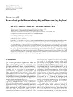
Figure 11: SNR results using IBM as the ground truth. W hite bars
show the results from unprocessed mixtures, black bars those from
the Hu and Wang model, and gray bars those from proposed system.
N0 N1 N2 N3 N4 N5 N6 N7 N8
N9
Intrusion
−1
−0.5
0
0.5
1
1.5
2
2.5
3
3.5
PESQ score
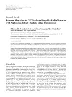
Figure 12: PESQ results using IBM as the ground truth. White bars
show the results from unprocessed mixtures, black bars those from
the Hu and Wang model, and gray bars those from proposed system.
algorithm to obtain the intrusive speech quality evaluation
result of the separated speech.
SNR is measured in decibel and computed by following
equation. The results are listed in Tab l e 1
SNR
= 10 log
10
t
R
(
t
)
2
t
[
R
(
t
)
− S
(
t
)]
2
, (18)
where R(t) is original voiced speech and S(t) is the synthe-
sized waveform by segregation systems.
EURASIP Journal on Audio, Speech, and Music Processing 11
Table 1: SNR Results. (Mixture: Original degraded speech; Hu-Wang: Hu and Wang model; Proposed: Proposed model; TP Hu-Wang: true
pitch-based Hu and Wang model; TP proposed: true pitch-based proposed model; IBM: Ideal binary mask)
N0 N1 N2 N3 N4 N5 N6 N7 N8 N9 Avg
Mixture −7.42 −8.27 5.62 0.80 0.68 −10.00 −1.62 3.85 9.53 2.75 −0.41
Hu-Wang 16.01 5.59 14.27 5.83 8.25 14.35 15.53 10.46 14.06 6.88 11.12
Proposed 17.95 6.32 17.76 6.51 9.44 14.99 17.45 11.97 15.27 8.33 12.60
TP Hu-Wang 16.16 5.64 14.74 6.43 9.58 14.44 16.49 11.14 14.76 7.39 11.68
TP proposed 17.95 6.36 17.79 6.97 9.60 14.98 17.43 11.97 15.30 8.33 12.67
IBM 20.05 6.84 18.46 7.97 11.33 15.75 19.90 13.86 17.65 11.21 14.30
The proposed system is compared with the Hu and
Wang model. Meanwhile, we also show the performance
of ideal binary mask (IBM) which is obtained by cal-
culating local SNR in each T-F unit and selecting units
(SNR > 0 dB) as the target. The SNR results of IBM
are the upper limit of all CASA-based systems which
employ “binary mask”. Ta b le 1 gives the variety of SNR
in which each value represents the average SNR of one
kind intrusion mixed with ten target utterances and the
last column shows the average SNR over all intrusions.
As shown in Table 1, proposed system improves SNR for
every intrusion and gets 13.01 dB improvement of overall
mean against unprocessed mixture. Compared with results
of the Hu and Wang model, proposed model enhances
the separation results about 1.48 dB for overall mean. The
highest enhancement of SNR happens on the mixtures of
N2 and is about 3.50 dB higher than the Hu and Wang
model. Other larger improvements (more than 1.0 dB) are
obtained for harmonic sound (N4, N5, N7, N8, and N9)
or tone-like sound (N0 and N6). While less improve-
ments are obtained for broadband noises (e.g., N1 and
N3).
To further compare the pitch detection algorithm and T-
F unit grouping method separately, we replace the estimated
pitchwithtruepitch(obtainedoncleanspeech)forboth
the Hu and Wang model and proposed system. From
Tab l e 1, we can see that true pitch makes the Hu and Wang
model enhance the SNR for 0.56 dB (from 11.12 dB to
11.68 dB). But the enhancement is tiny about 0.07 dB for the
true pitch-based proposed system. And the only noticeable
improvement is on N3 about 0.46 dB. The overall mean
of SNR of the tr ue pitch-based proposed system is about
1.00 dB higher than that of true pitch-based Hu and Wang
model.
Although conventional SNR is widely used, it does
not reflect the related perceptual effects, such as auditory
masking. As computational goal of CASA [24], IBM directly
corresponds to the auditory masking phenomenon. Recent
psychoacoustic experiments have demonstrated that t ar-
get speech reconstructed from the IBM can dramatically
improve the intelligibility of speech masked by different types
of noise, even in very noisy conditions [25]. Li and Wang
[26] also systematically compared the performance of IBM
and ideal ratio masks (IRM) and the results showed that
IBM is optimal as computational goal in terms of SNR gain.
Considering the advantages of IBM, we compute the SNR
and PESQ score using the speeches reconstructed from IBM
as the ground truth instead of clean speeches.
Figure 11 shows that the SNR of the proposed system
are much higher than unprocessed mixtures of all kinds of
intrusions. Compared to the performance of the Hu and
Wang model, the SNR of the proposed system has significant
improvement for all kinds of intrusions except for N3 and
N4 with small drops. To further obtain the voice quality
of seg regated speech, PESQ is employed as a measurement.
Figure 12 shows the PESQ scores of IBM against unprocessed
mixtures (white bars), segregated speeches from proposed
system (gray bars) and from the Hu and Wang model (black
bars) on ten kinds of intrusions. As Figure 12 showing, the
segregated speeches from proposed system obtain higher
PESQ scores on all ten kinds of intrusions (especially on N2,
N7, N8, and N9) than unprocessed mixtures and the outputs
of the Hu and Wang model.
Comparing the results of the Hu and Wang model, the
most S NR gain about 4 dB is obtained in N0 (pure tone) By
analyzing the segregated speeches, we found that the Hu and
Wang model groups many target units into the background.
It is mainly because some segments include both target units
and interference units. These kinds of segments are divided
into small ones by harmonic order in our system. Therefore,
it leads to the significant SNR gain. For N2 (click noise),
the SNR gain also due to the segmentation (see Figure 8).
The difference is that the Hu and Wang model groups many
interference units into foreground. It should be noticed that
the gains of PESQ scores on these two noises are d ifferent,
about 0.1 on N0 and 0.5 on N2, comparing with the Hu
and Wang model. It implies that the second error, grouping
intrusion units into foreground, has a greater impact on
speech perceptual quality.
Figure 13 shows the spectrograms of mixture of male and
female speech in (a), processed by IBM in (b), processed by
the Hu and Wang model (c), and processed by proposed
model (d). In Figure 13,wecanseethattheresultof
proposedmodelisclosertothatofIBM.However,theresult
of the Hu and Wang model has residual female speech.
5. Discussion
In sound separation, the application concerns about whether
a unit is dominated by a resolved harmonic or by unresolved
harmonics. Previous resear ch showed that this process is very
12 EURASIP Journal on Audio, Speech, and Music Processing
Time (s)
Frequency (kHz)
0 0.36 0.72 1.08 1.44 1.8
8
6
4
2
0
(a)
Time (s)
Frequency (kHz)
0 0.36 0.72 1.08 1.44 1.8
8
6
4
2
0
(b)
Time (s)
0
0.36 0.72 1.08 1.44
1.8
Frequency (kHz)
8
6
4
2
0
(c)
Frequency (kHz)
8
6
4
2
0
Time (s)
0 0.36 0.72 1.08 1.44 1.8
(d)
Figure 13: Spectrogram comparison: (a) mixture; (b) results of IBM; (c) results of the Hu and Wang model; (d) results of proposed model.
The input signal is male speech mixed with female speech.
important. Resolved and unresolved harmonics are relative
concepts which depend on the distance of harmonics and
also the resolution of gammatone filterbank. Therefore, the
decision of unit cannot be made by its channel frequency. A
reasonable decision is to check the filter response in unit. As
in previous research [15], cross-channel correlation is used
which measures the similarity between the responses of two
adjacent filters, indicates whether the filters are responding
to the same sound component. However, it is not reliable
for some units especially in high frequency region (as shown
in Figure 8(a)). Hence, we use a more direct measurement,
carrier to envelope energy ratio, to help classifying the
units.
ACF reflects the period information of the signal in a
unit. According to the “harmonicity” principle, each peak
position could be a pitch period. However, only one of them
corresponds to the true pitch period. DHF tends to reduce
thepeaksbythefactthatvoicedspeecheshavecontinuous
numbered harmonics. In noisy environment, it will lead to
errors when both neighbors of a harmonic are masked at the
same time. However, we found that these cases are relative
less.
Pitch detection is another key stage for sound separation.
Our algorithm uses only the longest resolved segment for
pitch detection. Based on this process, it is relative easy
for pitch tracking which is a difficult problem. It should
be pointed out that robustness of the system may reduce
when the interfering sounds dominate frequency regions
for resolved harmonics. However, resolved harmonics have
larger energy than unresolved ones. They are more robust
to noise. In addition, it should be pointed out that
EURASIP Journal on Audio, Speech, and Music Processing 13
DHF is generated based on the idea of continuous num-
bered harmonics. For sounds without this feature, DHF is
improper
6. Conclusions
In this paper, we propose the dynamic harmonic functions
which derive from conventional correlograms. DHF has the
uniform representation for both resolved and unresolved
units. Based on DHF, the pitch detection algorithm and
T-F unit grouping strategy are proposed. Results show that
proposed algorithm improves the SNRs for variety kinds of
noises over the Hu and Wang model.
Acknowledgments
This work was supported in part by the China National
Nature Science Foundation (no. 60675026, no. 60121302,
and no. 90820011), the 863 China National High
Technology Development Projects (no. 20060101Z4073,
no. 2006AA01Z194), and the National Grand Fundamental
Research 973 Program of China (no. 2004CB318105).
References
[1] J. Benesty, S. Makino, and J . Chen, Speech Enhancement,
Springer, Berlin, Germany, 2005.
[2] A. K. Barros, T. Rutkowski, F. Itakura, and N. Ohnishi,
“Estimation of speech embedded in a r everberant and
noisy environment by independent component analysis and
wavelets,” IEEE Transactions on Neural Networks, vol. 13, no.
4, pp. 888–893, 2002.
[3] M. Brandstein and D. Ward, Microphone Arrays: Signal Pro-
cessing Techniques and Applications, Springer, Berlin, Germany,
2001.
[4] S. F. Boll, “Suppression of acoustic noise in speech using
spectral subtraction,” IEEE Trans Acoust Speech Signal Process,
vol. 27, no. 2, pp. 113–120, 1979.
[5] Y. Ephraim and H. L. Van Trees, “Signal subspace approach for
speech enhancement,” IEEE Transactions on Speech and Audio
Processing, vol. 3, no. 4, pp. 251–266, 1995.
[6]A.S.Bregman,Auditory Scene Analysis, MIT Press, Cam-
bridge, Mass, USA, 1990.
[7] D. L. Wang and G. J. Brown, Computational Auditory Scene
Analysis: Principles, Algorithms and Applications, Wiley-IEEE
Press, New York, NY, USA, 2006.
[8] M.P.Cooke,Modeling A uditory Processing and Organization,
Cambridge University Press, Cambridge, UK, 1993.
[9] G. Hu and D. L. Wang, “Monaural speech segregation
based on pitch tracking and amplitude modulation,” IEEE
Transactions on Neural Networks, vol. 15, no. 5, pp. 1135–1150,
2004.
[10] J. C. R. Licklider, “A duplex theory of pitch perception,”
Experientia, vol. 7, no. 4, pp. 128–134, 1951.
[11] R. F. Lyon, “Computational models of neural auditory pro-
cessing,” in Proceedings of IEEE International Conference on
Acoustics, Speech, and Signal Processing (ICASSP ’84), pp. 41–
44.
[12] M. Weintraub, A theory and computational model of auditory
monaural sound separation, Ph.D. dissertation, Dept. Elect.
Eng., Stanford Univ., Stanford, Calif, USA, 1985.
[13] M. Slaney and R. F. Lyon, “A perceptual pitch detector,” in
Proceedings of the International Conference on Acoustics, Speech,
and Signal Processing, pp. 357–360, April 1990.
[14] R. Meddis and M. J. Hewitt, “Virtual pitch and phase
sensitivity of a computer model of the auditory periphery.
I: pitch identification,” Journal of the Acoustical Society of
America, vol. 89, no. 6, pp. 2866–2882, 1991.
[15]D.L.WangandG.J.Brown,“Separationofspeechfrom
interfering sounds based on oscillatory correlation,” IEEE
Transactions on Neural Networks, vol. 10, no. 3, pp. 684–697,
1999.
[16] M.Wu,D.L.Wang,andG.J.Brown,“Amultipitchtracking
algorithm for noisy speech,” IEEE Transactions on Speech and
Audio Processing, vol. 11, no. 3, pp. 229–241, 2003.
[17] A. Cheveigne, “Pitch and the n arrowed autocoindidence
histogram,” in Proceedings of the International Conference on
Music Perception and Cognition, pp. 67–70, Kyoto, Japan, 1989.
[18] J. C. Brown and M. S. Puckette, “Calculation of a “narrowed”
autocorrelation function,” Journal of the Acoustical Society of
America, vol. 85, no. 4, pp. 1595–1601, 1989.
[19] J. W. Xu and J. C. Principe, “A pitch detector based on a
generalized correlation function,” IEEE Transactions on Audio,
Speech and Language Processing, vol. 16, no. 8, pp. 1420–1432,
2008.
[20] E.DeBoerandH.R.DeJongh,“Oncochlearencoding:poten-
tialities and limitations o f the reverse-correlation technique,”
JournaloftheAcousticalSocietyofAmerica,vol.63,no.1,pp.
115–135, 1978.
[21] R. Meddis, “ Simulation of auditory-neural transduction:
further studies,” JournaloftheAcousticalSocietyofAmerica
,
vol. 83, no. 3, pp. 1056–1063, 1988.
[22] T. Tolonen and M. Karjalainen, “A computationally efficient
multipitch analysis model,” IEEE Transactions on Speech and
Audio Processing, vol. 8, no. 6, pp. 708–716, 2000.
[23] X. Zhang, W. Liu, P. Li, and BO. Xu, “Monaural voiced speech
segregation based on elaborate harmonic grouping strategy,”
in Proceedings of IEEE International Conference on Acoustics,
Speech, and Signal Processing (ICASSP ’09), pp. 4661–4664,
April 2009.
[24] D. L. Wang, “On ideal binary masks as the computational goal
of auditory scene analysis,” in Speech S eparation by Humans
and Machines, P. Divenyi, Ed., pp. 181–197, Kluwer Academic
Publishers, Boston, Mass, USA, 2005.
[25] N. Li and P. C. Loizou, “Factors influencing intelligibility of
ideal binary-masked speech: implications for noise reduction,”
JournaloftheAcousticalSocietyofAmerica, vol. 123, no. 3, pp.
1673–1682, 2008.
[26] Y. Li and D. Wang, “On the optimality of ideal binary time-
frequency masks,” Speech Communication,vol.51,no.3,pp.
230–239, 2009.