Advances in Solid State Part 10 pptx
Bạn đang xem bản rút gọn của tài liệu. Xem và tải ngay bản đầy đủ của tài liệu tại đây (1.71 MB, 30 trang )
Millimeter-Wave CMOS Impulse Radio
261
Data
(b) High speed
ASK modulator.
IN
OUT
IN
OUT
Data
(a) High isolation
ASK modulator.
Data
osc.
amp.
OUT
bias
Data
(b) High speed
ASK modulator.
IN
OUT
IN
OUT
IN
OUT
Data
IN
OUT
Data
(a) High isolation
ASK modulator.
Data
osc.
amp.
OUT
bias
(a) High isolation
ASK modulator.
Data
osc.
amp.
OUT
bias
Data
osc.
amp.
OUT
bias
Fig. 10. Architectures of conventional (a) high-isolation and (b) high-speed ASK modulators.
2.2.1 Millimeter-wave CMOS ASK modulator design
A possible distributed CMOS modulator is shown in Fig. 11(a). However, low-quality
parasitic capacitances in the switches, which are located on a silicon substrate, are expected
to degrade the transmission line characteristics. In this study, a reduced-switch architecture
is used for a high-speed millimeter-wave CMOS ASK modulator as shown in Fig. 11(b).
Note that the isolation characteristics become degraded upon reducing the number of
switches since each switch has a leakage to the output. To achieve high isolation with a
reduced number of switches, the transmission line length between switches is adjusted.
When the millimeter-wave signal travels from the source to the load, the switches do not
only dissipate the incident signal, but they also reflect and leak it as shown in Fig. 12. Note
IN OUT
Data
(a) Distributed-switch architecture.
(b) Reduced-switch architecture.
l
L
>>
l
D
IN
OUT
Data
l
L
l
L
l
D
IN OUT
Data
(a) Distributed-switch architecture.
(b) Reduced-switch architecture.
l
L
>>
l
D
l
L
>>
l
D
IN
OUT
Data
l
L
l
L
l
D
Fig. 11. Architectures of (a) distributive and (b) reduced-switch ASK modulators in CMOS
process.
Advances in Solid State Circuits Technologies
262
OFF
ON
t
Vout
t
1
0
P
leak
R
on
R
on
P
in
P
dis
P
ref
Source
side
Load
side
TL
P
out
R
off
l
R
off
P
in
Source
side
Load
side
ON
t
Vout
t
1
0
NMOSFET switches are OFF.
Output is ON.
Transmission line
NMOSFET switches are ON.
Output is OFF.
P
ref
(a)
(b)
ON
l
OFF
ON
t
Vout
t
1
0
P
leak
R
on
R
on
P
in
P
dis
P
ref
Source
side
Load
side
TL
P
out
R
off
l
R
off
P
in
Source
side
Load
side
ON
t
Vout
t
1
0
NMOSFET switches are OFF.
Output is ON.
Transmission line
NMOSFET switches are ON.
Output is OFF.
P
ref
(a)
(b)
ON
l
Fig. 12. Illustration of transmitted, reflected, dissipated and leaked signals of a switch in the
(a) ON and (b) OFF states of the modulator when the millimeter-wave signal travels from
source to the load.
high
Z
3
Z
2
low
Z
1
Z
2
high
low
Z
3
Z
4
high
λ/4 λ/2
P
leak
P
dis
P
ref
length, l
0
0
1
Power/P
in
(b)
R
on
R
on
l=λ/4
2
Z
0
R
on
Z
2
=Z
3
=R
on
Z
1
=R
on
Z
4
=
2
Z
0
R
on
R
on
<<Z
0
Load
side
Source
side
(a)
P
in
: Incident power
P
ref
: Reflected power
P
dis
: Dissipated power
P
leak
: Leaked power
high
Z
3
Z
2
high
Z
3
Z
2
low
Z
1
Z
2
high
low
Z
3
Z
4
high
low
Z
3
Z
4
high
λ/4 λ/2
P
leak
P
dis
P
ref
length, l
0
0
1
Power/P
in
(b)
R
on
R
on
l=λ/4
2
Z
0
R
on
Z
2
=Z
3
=R
on
Z
1
=R
on
Z
4
=
2
Z
0
R
on
R
on
<<Z
0
Load
side
Source
side
R
on
R
on
l=λ/4
2
Z
0
R
on
Z
2
=
2
Z
0
R
on
2
Z
0
R
on
Z
0
R
on
Z
2
=Z
3
=R
on
Z
1
=R
on
Z
4
=
2
Z
0
R
on
Z
4
=
2
Z
0
R
on
2
Z
0
R
on
Z
0
R
on
R
on
<<Z
0
Load
side
Source
side
(a)
P
in
: Incident power
P
ref
: Reflected power
P
dis
: Dissipated power
P
leak
: Leaked power
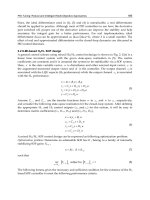
Fig. 13. (a) Impedance transformation along the modulator and (b) calculated reflected,
dissipated and leaked powers as a function of the transmission line distance between switches.
Millimeter-Wave CMOS Impulse Radio
263
that, in a transmission line, impedance transformation between the two terminals occurs as
shown in Fig. 13(a). In Fig. 13(b), the calculated leaked, reflected and dissipated powers are
shown as a function of the distance between switches. Since the dissipated power in the
switches is insensitive to the transmission line length, reflection should be maximized to
minimize the leakage. To obtain maximum reflected power and minimum leaked power, the
switches are separated by a quarter-wavelength distance. In this case, the isolation is
maximized with a lower number of switches.
A 60GHz CMOS ASK modulator is designed with three NMOSFET switches and two
quarter-wavelength transmission lines as shown in Fig. 14. When the digital input is 0V, the
NMOSFET switches are turned off. Since the parasitic capacitance of each switch in the OFF
state is negligible, the input impedance of each transmission line is equal to the load
impedance and the input power is transferred to the output. When the digital input is 1V,
the switches are turned on. The transmission line with a quarter wavelength transforms the
low impedance of the switch to a high impedance and reflection is maximized. In this case,
the leaked power to the output is minimized and high isolation is achieved.
IN
OUT
DATA
M1
M2
M3
R
g
R
g
R
g
60GHz
CW
baseband
source
50Ω
load
V
in
V
out
V
data
V
g1
V
g2
V
g3
CMOS
l=λ/4
l=λ/4
IN
OUT
DATA
M1
M2
M3
R
g
R
g
R
g
60GHz
CW
baseband
source
50Ω
load
V
in
V
out
V
data
V
g1
V
g2
V
g3
CMOS
l=λ/4
l=λ/4
Fig. 14. Circuit schematic of the CMOS ASK modulator for 60GHz wireless communication.
Millimeter-wave NMOSFET models are established by extracting the parasitic components
based on on-wafer measurements (Doan, 2005). The slow-wave transmission line (SWTL)
(Cheung, 2003) shown in Fig. 15 is used for implementing the quarter-wavelength
transmission lines and the networks between the circuit and the pads to reduce the size of
the modulator. In the SWTL, a slotted ground shield under the signal line is laid orthogonal
to the direction of the signal current flow. This structure results in the propagating waves
having lower phase velocity; thus, the corresponding wavelength at a given frequency is
reduced. A quarter wavelength is obtained using a 450-μm-long SWTL. Note that the
quarter wavelength would be 850μm if a microstrip line (MSL) was used.
200Ω gate resistors are inserted to ensure operation with sufficient high-speed. Transient
internal waveforms are simulated as shown in Fig. 16. A 200ps pulse is applied from the
data port to analyze the response of the circuit. The total time of the rising and falling gate
Advances in Solid State Circuits Technologies
264
Silicon
Slotted ground shield
6μm4μm6μm
G
r
o
u
n
d
m
e
t
a
l
S
i
g
n
a
l
G
r
o
u
n
d
m
e
t
a
l
M1
M2
M3
M4
M5
M6
M5
M6
M1
M2
M3
M4
M5
M6
Silicon
Slotted ground shield
6μm4μm6μm
G
r
o
u
n
d
m
e
t
a
l
S
i
g
n
a
l
G
r
o
u
n
d
m
e
t
a
l
M1
M2
M3
M4
M5
M6
M5
M6
M1
M2
M3
M4
M5
M6
Fig. 15. Structure of the slow-wave transmission line used in the circuit.
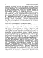
Tr+Tf=125ps
200ps
0
-0.2V
0.2V
00.5
1
0
0.5
1
00.51
0
0.5
1
0
1V
0
1V
0
-0.5V
0.5V
V
data
V
g1
V
IN
V
OUT
Time [ns]
Time [ns]
Time [ns]
Time [ns]
200ps
60GHz Pulse
at output
60GHz CW input signal
200ps baseband signal
8GHz gate bandwidth
(a)
(b)
(c)
(d)
Tr+Tf=125ps
200ps
0
-0.2V
0.2V
00.5
1
0
0.5
1
00.51
0
0.5
1
0
1V
0
1V
0
-0.5V
0.5V
V
data
V
g1
V
IN
V
OUT
Time [ns]
Time [ns]
Time [ns]
Time [ns]
200ps
60GHz Pulse
at output
60GHz CW input signal
200ps baseband signal
8GHz gate bandwidth
(a)
(b)
(c)
(d)
Fig. 16. Transient simulation; (a) 200ps applied data pulse, and responses of (b) the gate
voltage of the NMOSFET switch, and (c) input and (d) output signals.
voltages is estimated as 125ps, which corresponds to the maximum data rate of 8Gbps. The
60GHz millimeter-wave ASK modulator is fabricated by a 6-metal 1-poly 90nm CMOS
Millimeter-Wave CMOS Impulse Radio
265
process. The cutoff frequency f
T
and the maximum operation frequency of the nMOSFET are
130GHz and 150GHz, respectively. Figure 17 shows a micrograph of the fabricated ASK
modulator. The size of the chip is 0.8mm × 0.48mm including the pads. The core size is
0.61mm × 0.3mm.
0.8mmx0.48mm, chip size=0.484mm
2
0.61mmx0.3mm, core size=0.183mm
2
IN
OUT
Data
core
M1
M2
M3
G
G
G
G
SWTL
0.8mmx0.48mm, chip size=0.484mm
2
0.61mmx0.3mm, core size=0.183mm
2
IN
OUT
Data
core
M1
M2
M3
G
G
G
G
SWTL
Fig. 17. Micrograph of the fabricated chip.
2.2.2 Experimental result and discussion
On-wafer two-port measurements were performed up to 110-GHz with Anritsu ME7808
network analyzer with transmission reflection modules for the ON and OFF states by
applying 0V and 1V DC voltages to the gate terminal, respectively. The measured and
simulated insertion losses of the modulator for the two states are shown in Fig. 18(a) for
comparison. The insertion losses in the ON and OFF states are 6.6dB and 33.2dB,
respectively, at 60GHz. Isolation is defined as the insertion loss difference between the ON
and OFF states, which is 26.6dB. The isolation is nearly flat from 20 to 80GHz, although the
maximum isolation is measured at 60GHz. As a result, shorter transmission lines may be
adopted to reduce the insertion loss caused by the SWTL in the ON state of the modulator.
The simulated isolation is shown at frequencies up to 350GHz in Fig. 18(b) to demonstrate
0
25 50 75 100
Frequency [GHz]
-40
-30
-20
0
Insertion loss, S21 [dB]
-10
26.6dB
OFF
ON
■
Measured (ON)
▲
Measured (OFF)
Simulated (ON)
Simulated (OFF)
0
100
Frequency [GHz]
-40
-30
-20
0
Isolation [dB]
-10
200 300
◆ Measured
Simulated
0
25 50 75 100
Frequency [GHz]
-40
-30
-20
0
Insertion loss, S21 [dB]
-10
26.6dB
OFF
ON
■
Measured (ON)
▲
Measured (OFF)
Simulated (ON)
Simulated (OFF)
0
25 50 75 100
Frequency [GHz]
-40
-30
-20
0
Insertion loss, S21 [dB]
-10
26.6dB
OFF
ON
■
Measured (ON)
▲
Measured (OFF)
Simulated (ON)
Simulated (OFF)
■
Measured (ON)
▲
Measured (OFF)
Simulated (ON)
Simulated (OFF)
0
100
Frequency [GHz]
-40
-30
-20
0
Isolation [dB]
-10
200 300
◆ Measured
Simulated
0
100
Frequency [GHz]
-40
-30
-20
0
Isolation [dB]
-10
200 300
◆ Measured
Simulated
Fig. 18. Measured and simulated (a) insertion loss (S21) of the ASK modulator for ON and
OFF states and (b) isolation of the ASK.
Advances in Solid State Circuits Technologies
266
the frequency behaviour of the modulator. The minimum isolation appears at 60GHz when
the electrical length of the transmission lines is λ/4, where λ is the wavelength. Local
maxima in the OFF-state insertion loss occur at 180GHz and 300GHz, which correspond to
3λ/4 and 5λ/4, respectively.
The time-domain response is measured using a 70GHz sampling oscilloscope, a 60GHz
millimeter-wave source module and a pattern generator. No external filters are applied in
the measurement. A 60GHz continuous wave is applied to the RF input and the modulator
is controlled by the pattern generator. The rising and falling times of the applied baseband
signal are 6ps and 8ps, respectively. The output response for the maximum data rate is
shown in Fig. 19(a). In Fig. 19(b), the output response is shown for a 125ps single-baseband
pulse by reducing the scale to 20ps.
(a) (b)
On On On On
16.6ps
Off Off Off Off
100ps/div
20ps/div
(a) (b)
On On On On
16.6ps
Off Off Off Off
100ps/div
20ps/div
Fig. 19. Measured output response of the modulator for (a) an 8Gbps data train and (b) a
single 125ps data pulse.
The maximum data rates as a function of the isolation of the millimeter-wave ASK
modulators are shown in Fig. 20. It can be seen that the isolation and the maximum data rate
have a tradeoff relationship. The product of the maximum data rate and the isolation of this
modulator is 170GHz, which is the highest value among multi-Gbps ASK modulators.
2.3 12.1mW 10Gbps pulse transmitter for 60GHz wireless communication
In this section, we present a design of a low-power 10Gbps CMOS transmitter (TX) for a
60GHz millimeter-wave impulse radio, where a 60GHz millimeter-wave CW source and
ASK modulator circuits are embedded on the same silicon substrate as shown in Fig. 21. An
8Gb/s CMOS ASK modulator for 60GHz wireless communication is studied in Section 2.2.
This single-pole-single-throw (SPST) reduced NMOSFET switch architecture is capable of
high-speed operation without DC power dissipation. Its isolation was maximized by a
quarter-wave length transmission line which results in a long transmission lines, therefore
the insertion loss becomes high. Figure 22(a) shows TX configuration which consists of an
off-chip 60GHz millimeter-wave CW source and an on-chip CMOS modulator. Off-chip
millimeter-wave source module will increase the size, the total power consumption and the
cost of the TX system. The oscillator should be embedded in the CMOS chip for a practical
application. The millimeter-wave CMOS oscillators are commonly designed in differential
Millimeter-Wave CMOS Impulse Radio
267
Isolation [dB]
Maximum data rate [Gbps]
0.1
1
10
10
20
30
40 50
60
● Compound
semiconductor
▲ CMOS
1
0
G
H
z
This Work
60GHz
(Mizutani , 2000),60GHz
(Ohata, 2005), 60GHz
Isolation
×
Data Rate=170GHz
(Kosugi,
2003 & 2004),
120GHz
1
0
0
G
H
z
(Ohata, 2000), 60GHz
(Chang, 2007), 46GHz
Isolation [dB]
Maximum data rate [Gbps]
0.1
1
10
10
20
30
40 50
60
● Compound
semiconductor
▲ CMOS
1
0
G
H
z
This Work
60GHz
(Mizutani , 2000),60GHz
(Ohata, 2005), 60GHz
Isolation
×
Data Rate=170GHz
(Kosugi,
2003 & 2004),
120GHz
1
0
0
G
H
z
(Ohata, 2000), 60GHz
(Chang, 2007), 46GHz
Fig. 20. Maximum data rates as a function of isolation of the ASK modulators.
… 1 1 0 1
multi-Gbps
60GHz pulses
(multi-Gbps
digital data)
ANT
60GHz
pulse
receiver
CMOS
RX
60GHz
mm-wave
CW source
mm-wave
pulse
modulator
CMOS
digital circuitry
…1101
CMOS
this work
CMOS
digital circuitry
…1101
TX
ANT
… 1 1 0 1
multi-Gbps
60GHz pulses
(multi-Gbps
digital data)
ANT
60GHz
pulse
receiver
CMOS
RX
60GHz
mm-wave
CW source
mm-wave
pulse
modulator
CMOS
digital circuitry
…1101
CMOS
this work
CMOS
digital circuitry
…1101
TX
ANT
Fig. 21. Block diagram of a Giga-bit millimeter-wave wireless pulse communication in
CMOS.
ended (Huang, 2006). In this design a differential ended CMOS oscillator was designed for a
60GHz CW source. To utilize the differential-ended output signal, a double-pole-single-
throw (DPST) switch was proposed for modulator as shown in Fig. 22(b).
2.3.1 60GHz pulse transmitter design
2.3.1.1 60GHz CMOS CW Signal Source Design
Figure 23 shows the schematic of the on-chip 60GHz CW source circuit which consist of two
sub-blocks, a 60GHz oscillator and a buffer. The oscillator generates a 60GHz CW signal and
the buffer drives the ASK modulator. The 60GHz oscillator contains an on-chip transmission
Advances in Solid State Circuits Technologies
268
SPST
switch
off-chip 60GHz
mm-wave CW source
mm-wave pulse
modulator
Data IN
OUT
(a)
CMOS
SPST
switch
off-chip 60GHz
mm-wave CW source
mm-wave pulse
modulator
Data IN
OUT
(a)
CMOS
SPDT
switch
60GHz
oscillator
buffer
60GHz mm-wave
CW source
mm-wave pulse
modulator
Data IN
OUT+
OUT-
CMOS
Fig. 22. Architecture of (a) a single-ended millimeter-wave pulse transmitter with off-chip
60GHz CW source and (b) a proposed differential-ended pulse transmitter with on-chip
60GHz CW source.
OUT+
OUT-
buffer
VDD
resonator
tank
negative
conductance
OUT+
OUT-
buffer
VDD
resonator
tank
negative
conductance
Fig. 23. Circuit schematic of a 60GHz millimeter-wave continues-wave (CW) source.
line resonating tank with a MOS capacitor and two cross-coupled MOSFETs which realize a
negative conductance in parallel with the tank. The size of the devices was chosen by
considering the parasitic and the process variations to keep the resonation at the 60GHz
Millimeter-Wave CMOS Impulse Radio
269
millimeter-wave band. The active device and the MOS capacitor models were obtained from
the foundry. The transmission lines were characterized by a 3D full-wave electromagnetic
field simulation using high-frequency structure simulator (HFSS).
The bias voltage does not only affect the negative conductance but also power consumption.
High supply voltage results in a high-power dissipation. Even though a maximum 1.2V
supply voltage is allowed in this CMOS process, it is simulated in spectre RF that the
oscillation starts when the supply voltage is approximately 0.9V. 0.1V was decided as a
margin and the supply voltage was set to be 1V for low-power operation.
2.3.1.2 Millimeter-wave Differential Ended CMOS ASK Modulator Design
Figure 24 shows the 60Hz differential ended CMOS ASK modulator. It is designed by a
DPST switch consisting of a parallel connected two SPST switches. The inputs are connected
to the complementary outputs of the on-chip 60GHz signal source. The gates of the switches
are controlled by binary data. Each SPST switch is designed with two NMOSFET switches
and a transmission line, TL1 as shown in Fig. 24. When the digital input is 0V, the
NMOSFET switches are turned off. Since the parasitic capacitance of each switch in the OFF
state is negligible, the input impedance of each transmission line is equal to the load
impedance and the input power is transferred to the output as shown in Section 2.2 Fig.
12(a). When the digital input is 1V, the switches are turned on. The transmission line
transforms the low impedance of the switch to high impedance and reflection is increased.
In this case, the leaked power to the output is reduced and isolation is improved as shown
in Section 2.2 Fig. 12(b).
OUT+
OUT-
IN+
IN-
Data IN
M1
M2
M3
M4
TL1
TL2
OUT+
OUT-
IN+
IN-
Data IN
M1
M2
M3
M4
TL1
TL2
Fig. 24. Circuit schematic of the differential-ended ASK modulator for 60GHz millimeter-
wave pulse transmitter.
The isolation is theoretically maximized when the switches are separated by a quarter-
wavelength transmission line however long transmission lines result higher insertion loss.
The isolation was maximized with two quarter-wavelength transmission lines whose total
length is 900μm which results in 6.6dB insertion loss in Section 2.2. The isolation is nearly
flat from 20 to 80GHz, although the maximum isolation is measured at 60GHz. As a result,
shorter transmission lines may be adopted to reduce the insertion loss caused by the on-chip
transmission line in the ON state of the modulator. In this CMOS technology, the length of a
quarter-wavelength transmission line is 600μm. We designed the switch with a 300μm long
transmission line where the isolation will slightly degrade but the insertion loss will
improve.
Advances in Solid State Circuits Technologies
270
2.3.2 60GHz pulse transmitter measurement and discussions
The proposed pulse transmitter, a 60GHz millimeter-wave source and an ASK modulator
test circuits were fabricated by an 8-metal-1-poly 90nm CMOS process with a rewiring layer
fabricated by a wafer-level chip-scale package (W-CSP). Figure 25 shows the micrographs of
the pulse transmitter chip. In this design, the pitch of radio frequency and the biasing pads
are designed 150μm.
IN+
60GHz CW
source
Modulator
OUT+
OUT-
Data IN
IN+
60GHz CW
source
Modulator
OUT+
OUT-
Data IN
Fig. 25. Micrograph of the fabricated 60GHz pulse transmitter chip.
2.3.2.1 60GHz CW signal source
The spectrum of the 60GHz CW signal source was measured using an Agilent E4407B
spectrum analyzer and an Agilent 11970V 50-75GHz harmonic mixer. A 60GHz continues-
wave signal was measured at the output of the circuit whose spectrum is shown in Fig. 26.
In this measurement setup, the total power loss of the probe, cables, connecters and
harmonic mixer is approximately 42dB. It was observed that the fabricated chip starts to
oscillate when the bias voltage is larger than 0.7V. The measured operating frequency as a
function of supply voltage is plotted in Fig. 27(a). Figure 27(b) shows the power dissipation
and millimeter-wave RF power as a function of the supply voltage from 0.7V to 1.4V. As the
supply voltage increases, the power dissipation rapidly increases. However, the millimeter-
wave output power saturates when the supply voltage reaches near to 1V. The power
Fig. 26. Measured output spectrum of the 60GHz CW source.
Millimeter-Wave CMOS Impulse Radio
271
58
59
60
61
0.7 0.9 1.1 1.3
VDD [Volt]
Frequency [GHz]
0
10
20
30
0.70.91.11.3
-40
-30
-20
-10
0
VDD [Volt]
Power dissipation [mW]
Mm-Wave Power [dBm]
(b)
(a)
58
59
60
61
0.7 0.9 1.1 1.3
VDD [Volt]
Frequency [GHz]
0
10
20
30
0.70.91.11.3
-40
-30
-20
-10
0
VDD [Volt]
Power dissipation [mW]
Mm-Wave Power [dBm]
0
10
20
30
0.70.91.11.3
-40
-30
-20
-10
0
VDD [Volt]
Power dissipation [mW]
Mm-Wave Power [dBm]
(b)
(a)
Fig. 27. Measured (a) operating frequency of the oscillator and (b) power dissipation and
output millimeter-wave power of the oscillator as a function of supply voltage.
dissipation was measured to be a 19.2mW at a maximum allowed supply voltage of 1.2V.
We reduced to the supply voltage to 1V for low-power operation where the millimeter-wave
output power was measured to be -20.7dBm and power dissipation of 12.1mW. In this
study, we found out that our layout versus schematic verification software had not been
functioning properly while we had been designing the circuit using this 90nm CMOS
technology first time. The core of the oscillator operates properly; however, because of the
verification error in the layout, we noticed that the buffer attenuates the generated
millimeter-wave signal by 18dB although it was designed to have 10dB gain.
2.3.2.2 Millimeter-wave CMOS ASK Modulator
0
20
40 60
80
100
Frequency [GHz]
Insertion, S21 [dB]
-30
-20
-10
0
V
GATE
=0V
V
GATE
=VDD
Isolation=23dB
0
20
40 60
80
100
Frequency [GHz]
Reflection, S11 [dB]
-30
-20
-10
0
V
GATE
=0V
V
GATE
=VDD
(a) (b)
0
20
40 60
80
100
Frequency [GHz]
Insertion, S21 [dB]
-30
-20
-10
0
V
GATE
=0V
V
GATE
=VDD
Isolation=23dB
0
20
40 60
80
100
Frequency [GHz]
Reflection, S11 [dB]
-30
-20
-10
0
V
GATE
=0V
V
GATE
=VDD
(a) (b)
Fig. 28. Measured (a) insertion loss (S21) and (b) reflection loss (S11) of the ASK modulator
for ON and OFF states.
The scattering parameters of the ASK modulator test circuit were measured on-wafer up to
110GHz with Anritsu ME7808 network analyzer with transmission reflection modules for
Advances in Solid State Circuits Technologies
272
the ON and OFF states, respectively. The measured insertion losses of the modulator for the
two states are shown in Fig. 28(a). When the gate voltage is 0 volt, the insertion loss was
measured to be a 2.3dB at 60GHz. When the gate voltage was increased to VDD, the
insertion loss became 25.8dB therefore isolation was calculated to be 23.5dB at 60GHz,
which is defined as the insertion loss difference between the ON and OFF states. Figure
28(b) shows the measured reflection of loss of the modulator for the two states. When the
modulator is ON, S11 is lower than -10dB up to 75GHz and it was measured to be a -16.2dB
at 60GHz where it was matched to 50Ω system. When the modulator was turned on by
increasing the gate voltage, the S11 became -5.2dB. The maximum data rates as a function of
the isolation of the millimeter-wave ASK modulators are shown in Fig. 29. It can be seen
that the isolation and the maximum data rate have a tradeoff relationship. The product of
the maximum data-rate and the isolation of this modulator is slightly less than the previous
work in Section 2.2 but its maximum data is increased by 2Gbps and the insertion loss is
improved by 4.3dB.
Isolation [dB]
Maximum data rate [Gbps]
0.1
1
10
10
20
30
40 50
60
● Compound
semiconductor
▲ CMOS
1
0
G
H
z
1
0
0
G
H
z
(Kosugi,
2003 & 2005)
120GHz
This Work
60GHz
(Mizutani, 2000), 60GHz
(Ohata, 2005), 60GHz
(Oncu, 2008, b), 60GHz
(Chang, 2007), 46GHz
(Ohata, 2000), 60GHz
Isolation [dB]
Maximum data rate [Gbps]
0.1
1
10
10
20
30
40 50
60
● Compound
semiconductor
▲ CMOS
1
0
G
H
z
1
0
0
G
H
z
(Kosugi,
2003 & 2005)
120GHz
This Work
60GHz
(Mizutani, 2000), 60GHz
(Ohata, 2005), 60GHz
(Oncu, 2008, b), 60GHz
(Chang, 2007), 46GHz
(Ohata, 2000), 60GHz
Fig. 29. Maximum data rates as a function of isolation of the ASK modulators.
2.3.2.3 60GHz Pulse Transmitter
The time-domain response of the pulse transmitter was measured using an Agilent
Infiniium DCA 86100B wide-bandwidth oscilloscope with an Agilent 86118A 70GHz remote
sampling module. The chip was measured by on-waver. The output is connected to the
sampling oscilloscope by on-wafer probe and cables. The measurements were performed
without any external filters at the output. The internal impedance of the measurement
equipment is equal to a 50Ω. Figure 30(a) and Fig. 30(b) show the output response for 1Gbps
and 10Gb/s respectively. Due to the high-speed binary base-band signal leakage from the
gate, the baseline varied. Especially the leakage became stronger at 10GHz but it will not
distort the transmitted millimeter-wave signal since the base-band leakage will be filtered
Millimeter-Wave CMOS Impulse Radio
273
out in the 60GHz band antenna. The RF power can be measured from the time-domain
response shown in Fig. 31. The maximum peak-to-peak voltage was measured to be 45mV
for a 50Ω load impedance. It corresponds to -23dBm peak power. By using this circuit up
10Gbps short-range wireless or proximity communication can be realized a power
dissipation of 12.1mW. Our study showed us that with a proper buffer design and improved
layout verifications, the output RF power would be increased up to a few dBm with an
additional cost of a few tens of mW power dissipation for longer range applications.
(a) 1Gbps
(b) 10Gbps
45mV
On On On
Off Off Off
500ps/div, 10mv/div
50ps/div, 15.8mV/div
Off Off Off
On On On
(a) 1Gbps
(b) 10Gbps
45mV
On On On
Off Off Off
500ps/div, 10mv/div
50ps/div, 15.8mV/div
Off Off Off
On On On
Fig. 30. Measured output response of the transmitter for (a) a 1Gb/s and (b) a 10Gb/s data
trains.
3. 60GHz CMOS pulse receiver
In the past few years, millimeter-wave quadrature amplitude modulator (QAM) receiver
circuits in the short-channel standard CMOS process have been reported with a several
Gbps data rate and a better energy-per-bit efficiency than WLAN and UWB (Pinel , 2007).
Conventional QAM receivers downconvert the received millimeter-wave signal to baseband
using one or two voltage-controlled oscillator (VCO) and phase-locked loop (PLL) circuits.
However, these building blocks consume several tens of mW. Additionally, total power
consumption further increases using an analog-to-digital converter and a high-speed
modulator, particularly when the data rate exceeds 1Gbps. By removing these power-
hungry building blocks, 2Gbps and 5Gbps millimeter-wave CMOS impulse radio receivers
were developed with a better power efficiency. The 2Gbps receiver detects millimeter-wave
single-ended pulses using a single-ended CMOS envelope detector, and high-speed data is
only processed using a limiting amplifier. The second receiver design contains a differential
envelope detector, a voltage control amplifier, a current mode offset canceller and the data is
processed using a high-speed comparator with hysteresis. In this section, 2Gbps and 5Gbps
millimeter-wave CMOS impulse radio receivers will be studied.
3.1 19.2mW 2Gbps CMOS pulse receiver
The general architecture of conventional millimeter-wave QAM receivers is shown in Fig.
31(a), where the received signal is downconverted using a local oscillator (LO) consuming a
power of several tens of mW (Razavi, 2007; Mitomoto, 2007). Also, total power dissipation
will even increase using a high-speed analog-to-digital converter (ADC) and a high-speed
Advances in Solid State Circuits Technologies
274
demodulator (DMOD), particularly for the multi-Gbps data rate. Instead of using an LO, an
ADC and a DMOD, a low-power CMOS pulse receiver is proposed in this work for multi-
Gbps wireless communication, as shown in Fig. 31(b). The architecture is adopted from that
of optical communication receivers due to the similarity between an optical pulse and a
millimeter-wave pulse. In the following sections, the pulse receiver design and the
measurement results are presented.
LNA
MIX
LO
AMP
ADC
DMOD
…1101
CMOS
digital
circuitry
(high-speed
digital data)
ANT
LNA
LA
(high-speed
digital data)
ANT
… 1 1 0 1
Millimeter-wave
pulses
(a)
(b)
…1101
CMOS
digital
circuitry
This work
Detector
LNA
MIX
LO
AMP
ADC
DMOD
…1101
CMOS
digital
circuitry
(high-speed
digital data)
ANT
LNA
LA
(high-speed
digital data)
ANT
… 1 1 0 1
Millimeter-wave
pulses
(a)
(b)
…1101
CMOS
digital
circuitry
This work
Detector
Fig. 31. Architectures of (a) a conventional 60GHz receiver and (b) the proposed 60GHz
pulse receiver.
3.1.1 19.2mW 2Gbps CMOS pulse receiver design
Multi-Gbps communication will have low power consumption when a received signal is
detected without using a high-frequency LO and high-speed data are processed using only a
limiting amplifier (LA), as shown in Fig. 31(b). Figure 32(a) shows the widely used optical
receiver architecture (Narasimha, 2007; Le, 2004). By adopting a similar principle, a 60GHz-
band CMOS pulse receiver used for investigating the above concept is shown in Fig. 32(b).
Here, a low-noise amplifier (LNA) is not implemented in this work to determine the
inherent features of the millimeter-wave pulse receiver. As a result, the receiver consists of a
nonlinear amplifier (NLA), a five-stage LA, an off-set canceller and an output buffer. To
detect the millimeter-wave pulses, a metal-insulator-insulator-metal (MIIM) diode
(Rockwell, 2007) or a Schottky diode (Sankaran, 2005) was conventionally used. However,
the MIIM diode is used in special CMOS process, thus increasing the cost of the pulse
receiver. And a Schottky diode is not always available in general design rules. To overcome
this issue, a common-source amplifier, utilizing a square-law relationship between the drain
current I
d
and the gate voltage V
g
of an NMOSFET, is used as a detector. In the NLA, V
g
is
adjusted to maximize ∂
2
I
d
/∂V
g
2
to detect the envelope of the millimeter-wave pulses
efficiently. At the output of the NLA, the base-band signal is generated as shown in Fig. 33.
The remainder of the circuitry is designed in the same way as for similar types of optical
receivers.
Millimeter-Wave CMOS Impulse Radio
275
Photo
Diode
TIA
DC-offset
canceller
LA
Buffer
Optical
pulse
Data
output
Limiting Amplifier
NLA
VP
VM
DUM
VIN
CMOS
DC-offset
canceller
(detector)
Data
output
Buffer
mm-Wave
pulse
(a)
(b)
Photo
Diode
TIA
DC-offset
canceller
DC-offset
canceller
LA
Buffer
Optical
pulse
Data
output
Limiting Amplifier
NLA
VPVP
VM
VM
DUMDUM
VINVIN
CMOS
DC-offset
canceller
DC-offset
canceller
(detector)
Data
output
Buffer
mm-Wave
pulse
(a)
(b)
Fig. 32. (a) Typical optical receiver architecture and (b) diagram of receiver block in this
work to realize the proposed pulse receiver.
t
t
V
out
V
in
0
Vin [V]
0.2
0.4
0.6
0.8
1.0
0
0.2
0.4
0.6
0.8
1.0
Vout [V]
Base-band signal
is generated.
V
out
V
in
R
D
VDD
Common-
source
amplifier
t
t
V
out
V
in
0
Vin [V]
0.2
0.4
0.6
0.8
1.0
0
0.2
0.4
0.6
0.8
1.0
Vout [V]
Base-band signal
is generated.
V
out
V
in
R
D
VDD
V
out
V
in
R
D
VDD
Common-
source
amplifier
Fig. 33. Nonlinear pulse detection using a common-source amplifier.
3.1.2 Measurement and discussions
The receiver was fabricated by a 90nm CMOS process. A micrograph of the receiver is
shown in Fig. 34. The millimeter-wave switch in Section 2.2 was used for measurement. A
60GHz continuous-wave (CW) signal applied to the switch input is modulated using a
pattern generator in a bit-error-rate tester (BERT). To filter out base-band fluctuations due to
switching, a V-band waveguide is inserted between the transmitter and the receiver. Before
applying the pulses to the receiver input, the average pulse power is measured using a
Advances in Solid State Circuits Technologies
276
millimeter-wave power meter. The 60GHz pulses and the demodulated digital signals
transmitted at a data rate of 2Gbps are shown in Fig. 35. The eye diagram and bit-error rate
(BER) of the receiver are obtained using 2
31
-1 bits of pseudo-random data. The eye diagram
of the receiver is shown in Fig. 36 for the data rates of 1 and 2Gbps. In both cases, clear eye
openings are observed. The output was 313mV peak to peak. The measured BER with
respect to the average pulse power is plotted in Fig. 37 for 1 and 2Gbps data rates. The
theoretical BER curves for the case of square-law detection are fitted to the measured data,
the shapes of which agree with the square-law detection theory. The BER of the pulse
receiver decreases more rapidly with increasing input power than that of a linear-detection
receiver.
VSS
VDD
VIN
VM
VP
DC-offset
canceller
DC-offset
canceller
NLA
DUM
725μm
565μm
LA
Buffer
VSS
VDD
VIN
VM
VP
DC-offset
canceller
DC-offset
canceller
NLA
DUM
725μm
565μm
LA
Buffer
Fig. 34. Micrograph of the pulse receiver.
2Gbps
0110101 0010110 101001011 0101 0010110 101001
60GHz input
pulse (VIN)
Negative output of
the receiver (VM)
Binary data
2Gbps
0110101 0010110 101001011 0101 0010110 101001
60GHz input
pulse (VIN)
Negative output of
the receiver (VM)
Binary data
Fig. 35. Receiver input and output waveforms for pseudo-random data.
Millimeter-Wave CMOS Impulse Radio
277
1Gbps
1ns
313 mV
2Gbps
0.5ns
313 mV
1Gbps
1ns
313 mV
2Gbps
0.5ns
313 mV
Fig. 36. Eye diagram with 2
31
-1 random bits of data at 1 and 2Gbps data rates.
Average 60GHz pulse power [dBm]
Bit Error Rate (BER)
10
-
12
10
-
10
10
-
8
10
-
6
10
-
4
10
-
2
10
0
-30 -10
-20
1Gbps
2Gbps
-15
-25
Average 60GHz pulse power [dBm]
Bit Error Rate (BER)
10
-
12
10
-
10
10
-
8
10
-
6
10
-
4
10
-
2
10
0
-30 -10
-20
1Gbps
2Gbps
-15
-25
Fig. 37. Bit error rate with 2
31
-1 random bits of data at 1 and 2Gbps data rates.
The total power consumption of the pulse receiver including the buffer is 19.2mW. To
compare between this receiver and optical receivers, a figure of merit FOM is determined as
G•DR/P
DC
, where G is the power gain, DR is the data rate, and P
DC
is the power
consumption. The product of G and DR is plotted as a function of PDC, as shown in Fig. 38,
where the FOMs are given by the slope. The FOM of this receiver is a slightly better than
1
10
100
1000
10000
1 10 100 1000 10000
This
work
(Chen,
2006)
(Le, 2004)
(Werker,2004)
(Palermo,2007)
(Swoboda, 2006)
(Krishnapura,
2005)
(Seidl,2004)
G
.
DR [Gbps]
P
DC
[mW]
1000100
10
1
10000
1000
100
10
1
1
0
b
i
t
/
p
J
1
0
0
b
i
t
/
p
J
1
b
i
t
/
p
J
0
.
1
b
i
t
/
p
J
0
.
0
1
b
i
t
/
p
J
(Radovanovic,
2004)
(Narashimha
2007)
10000
1
10
100
1000
10000
1 10 100 1000 10000
This
work
(Chen,
2006)
(Le, 2004)
(Werker,2004)
(Palermo,2007)
(Swoboda, 2006)
(Krishnapura,
2005)
(Seidl,2004)
G
.
DR [Gbps]
P
DC
[mW]
1000100
10
1
10000
1000
100
10
1
1
0
b
i
t
/
p
J
1
0
0
b
i
t
/
p
J
1
b
i
t
/
p
J
0
.
1
b
i
t
/
p
J
0
.
0
1
b
i
t
/
p
J
(Radovanovic,
2004)
(Narashimha
2007)
This
work
(Chen,
2006)
(Le, 2004)
(Werker,2004)
(Palermo,2007)
(Swoboda, 2006)
(Krishnapura,
2005)
(Seidl,2004)
G
.
DR [Gbps]
P
DC
[mW]
1000100
10
1
10000
1000
100
10
1
1
0
b
i
t
/
p
J
1
0
0
b
i
t
/
p
J
1
b
i
t
/
p
J
0
.
1
b
i
t
/
p
J
0
.
0
1
b
i
t
/
p
J
(Radovanovic,
2004)
(Narashimha
2007)
10000
Fig. 38. Product of gain and data rate as a function of power dissipation for the receivers in
this work and previously reported optical receivers.
Advances in Solid State Circuits Technologies
278
those of other reported optical receivers. It was shown by measuring the scattering
parameters that suitable input matching would increase the power gain by 4.9dB. The
receiver is also compared with recently reported millimeter-wave receivers in Table 1. Note
that digital codes are provided at the output with only 19.2mW of the power consumption
using the proposed pulse receiver.
A low-power 60GHz-band CMOS pulse receiver was proposed for multi-Gbps wireless
communication. Using a 90nm 1P6M standard CMOS process, the proposed pulse receiver
achieved a 2Gbps data rate with a total power dissipation of 19.2mW, which consumes less
power than recently reported 60GHz receivers. The performance of this pulse receiver
indicates the possibility of new low-power multi-Gbps wireless communication at the
60GHz band.
DC Power Missing Building Blocks
This Work 19.2mW LNA
(Afshar, 2008) 24mW PLL, DMOD
(Parsa, 2008) 36mW DMOD
(Scheir, 2008) 65mW DMOD
(Razavi, 2007) 80mW DMOD
(Mitomoto, 2007) 144mW DMOD
Table 1. Comparison of 60GHz receivers.
3.2 49mW 5Gbps CMOS receiver
The receiver circuit in Section 3.1 operates up to a 2Gbps data rate with a total power
dissipation of 19.2mW, consuming less power than conventional 60GHz millimeter-wave
QAM receivers. However, it suffers from input common-mode noise, sensitivity to supply
voltage, and an insufficient data rate for 4.5Gbps wireless high-definition multimedia
interface applications. To overcome these issues, a fully differential 5Gbps millimeter-wave
CMOS impulse radio receiver in an 8M1P 90nm standard CMOS process was realized. The
receiver contains an on-chip matching circuit, a fully differential envelope detector, a
voltage-controlled amplifier (VGA), a current-mode offset canceller, a high-speed
comparator with hysteresis.
3.2.1 49mW 5Gbps CMOS receiver design
A block diagram of the proposed receiver is shown in Fig. 39. The on-chip matching
network is used for 50Ω impedance matching and also helps reject the off-band signals. The
envelope detector detects the envelope of the received pulses; the VGA amplifies the
received signal to the required level, and then the high-speed comparator processes the
signal. The current-mode offset canceller circuit both cancels the offset due to the
mismatching of the differential amplifiers through the receiver chain and drives the
NMOSFETs of the fully differential envelope detector.
Input signals are first given to the fully differential envelope detector through the input
matching circuit. In practical applications an LNA will be included at the input of the
receiver. Unlike the single-ended LNA, the differential LNA is superior in terms of
common-mode noise rejection (Sun, 2006). The degradation of the common-mode noise will
be stronger for an impulse radio receiver since the analog front-end and the logic circuits
share the same substrate. To solve this issue, a fully differential CMOS envelope detector is
Millimeter-Wave CMOS Impulse Radio
279
designed. The fully differential envelope detector (FDD) is shown in Fig. 40, along with a
conventional single-ended detector (SED) for comparison. The SED used in Section 3.1 only
detects single-ended pulses. In the proposed FDD, the differential signals are applied to the
gates of two parallel NMOSFETs with the same size. Also, an active balun is used for
generating a differential output and common-mode rejection as shown in Fig. 40. The FDD
rejects common-mode noise from the substrate and power line.
input
Current-mode offset canceller
Level
shifter
matching
network
Comparator
VGA
Digital
output
VI
converter
Vin
-
Vin
+
Vout-
Vout+
Fully differential
envelope detector
I
ref
Low-pass
filter
I
fb
-
IN+
IN-
FB+
FB-
I
fb
+
OUT+
OUT-
input
Current-mode offset canceller
Level
shifter
matching
network
Comparator
VGA
Digital
output
VI
converter
Vin
-
Vin
+
Vout-
Vout+
Fully differential
envelope detector
I
ref
Low-pass
filter
I
fb
-
IN+
IN-
FB+
FB-
I
fb
+
OUT+
OUT-
Fig. 39. Block diagram of fully differential 60GHz band millimeter-wave CMOS impulse
radio receiver.
M2 M3
Fully differential
envelope detector
(FDD)
Vin
+
Vin
-
VDD
Vout
Single-ended
envelope detector
(SED)
M1
Vin
Vbias
VDD
VoutM
VbiasP
M4
VoutP
I
fbM
M5
M5
I
fbP
λ/4
λ/4
Active balun
M6
M7
IN+
IN-
FB+
FB-
OUT+
OUT-
IN
OUT
Load
M2 M3
Fully differential
envelope detector
(FDD)
Vin
+
Vin
-
VDD
Vout
Single-ended
envelope detector
(SED)
M1
Vin
Vbias
VDD
VoutM
VbiasP
M4M4
VoutP
I
fbM
M5M5
M5
I
fbP
λ/4
λ/4
Active balun
M6
M7
IN+
IN-
FB+
FB-
OUT+
OUT-
IN
OUT
Load
Fig. 40. Millimeter-wave CMOS envelope detector circuits.
Advances in Solid State Circuits Technologies
280
0.1
0.2
0.3
0
Second order nonlinearity,
∂
2
Id/∂Vg
2
[A/V
2
]
0.2
0.4
0.6
0.80
1
Drain Current, I
D
[mA]
0.1
0.2
0.3
1
2
3
4
0
0
Gate source Voltage, V
G
[V]
Second order nonlinearity,
∂
2
Id/∂Vg
2
[A/V
2
]
5
I
ref
V
ref
0.1
0.2
0.3
0
Second order nonlinearity,
∂
2
Id/∂Vg
2
[A/V
2
]
0.2
0.4
0.6
0.80
1
Drain Current, I
D
[mA]
0.1
0.2
0.3
1
2
3
4
0
0
Gate source Voltage, V
G
[V]
Second order nonlinearity,
∂
2
Id/∂Vg
2
[A/V
2
]
5
I
ref
V
ref
Fig. 41. Second-order nonlinearities with respect to drain current and to gate voltage.
To improve the immunity of PVT variations, current-mode offset canceller is proposed. The
envelope detector circuits, driven by the offset canceller as well as 60GHz input pulses,
detect the envelope of the pulses using the square-law relationship between the drain
current I
d
and the gate voltage V
g
of the NMOSFETs. In (Oncu, 2008, a), V
g
was adjusted to
maximize ∂
2
Id/∂V
g
2
to detect the envelope of the millimeter-wave pulses efficiently, where
V
g
is determined by the output common-mode voltage of the limiting amplifier. Here, the
simulated second-order nonlinearity with respect to I
d
is shown in Fig. 41, along with that
with respect to V
g
for comparison. The maximum nonlinearity is obtained when the
transistor is biased in the moderate inversion region in both cases. However, since the peak
characteristics of the nonlinearity with regard to I
d
are flatter than that with regard to V
g
, the
nonlinearity is insensitive to the deviation from the maximum point due to the PVT
variations when the drain current I
d
is adjusted with respect to a reference current I
ref
and
the envelope of the millimeter-wave pulses is efficiently detected. To utilize this advantage,
the current-mode offset canceller is used, which contains a level shifter, a low-pass filter, a
voltage-independent reference current generator, and a VI converter.
A high-speed comparator with hysteresis is used in this design to process the input signal
with rejecting a noise. Its circuit schematic is shown in Fig. 42. It has three subcirctuis: a
positive-feedback decision circuit, a predriver, and a line driver. In the positive-feedback
decision circuit, a differential driver and a positive-feedback load are composed of
NMOSFETs to realize high speed with moderate bias current. No stacking transistor is used
in the load to maximize an output voltage swing. Two current mirrors by PMOSFETs are
used between the driver and the load. Since the operating speed of the PMOSFET current
mirrors has to be improved to realize high-speed operation, higher overdrive voltage is
applied to the PMOSFETs than to the NMOSFETs. The predriver utilizes a PMOSFET
differential pair to obtain sufficient bias voltage since the output common-mode voltage of
the positive-feedback decision circuit is reduced. The CMOS line driver is used for the final
stage. The comparator test circuit is measured at a data rate up to 6Gb/s with 500mVpp
Millimeter-Wave CMOS Impulse Radio
281
output voltage swing at a supply voltage of 1.2V and a current of 11.9mA, where the power
consumption of the line driver is included.
VDD
Predriver
VDD
Vin+
Vin-
Positive feedback decision circuit
Line driver
VDD
VDD
Vout-
Vout+
M1
M2
M3
M4
M5
M6
M7
I
1
I
2
M8
M9
M10
M11
M12
M13
M14
M15
M16
PMOS current mirrors
VDD
Predriver
VDD
Vin+
Vin-
Positive feedback decision circuit
Line driver
VDD
VDD
Vout-
Vout+
M1
M2
M3
M4
M5
M6
M7
I
1
I
2
M8
M9
M10
M11
M12
M13
M14
M15
M16
PMOS current mirrors
Fig. 42. High-speed CMOS comparator with hysteresis.
3.2.2 Measurement and discussion
The fabricated receiver is measured using an on-wafer probe station. The chip micrograph is
shown in Fig. 43, where the chip size is 950µm × 750µm. The input reflection coefficient of
the receiver was measured using a 4-port network analyzer. S11
dd
is less than -10dB at
frequencies from 60GHz to 64GHz. Using an 8Gbps ASK CMOS modulator in Section 2.2
millimeter-wave pulses are generated to characterize the dynamic behaviour of the receiver.
62GHz differential ended pulses are applied to the input of the receiver using a magic tee,
and the receiver is also tested using single-ended pulses. The receiver can receive 62GHz
short-pulses in a time as short as 200ps. The measured receiver sensitivity is approximately -
20dBm, which is suitable for high-speed millimeter-wave proximity communication
applications. An LNA and a high-gain antenna will improve the sensitivity for long-range
applications. An eye diagram of the receiver is obtained using 2
31
-1 pseudorandom bits of
data. The eye diagram obtained at a data rate of 5Gb/s data requires a total power
consumption of 49mW. Measured results of the receiver performance are summarized in
Fig. 44. The power consumptions of recently reported wireless digital receivers are
compared in Fig. 45. The slope shows the figure of merit and the energy per bit. The graph
shows that millimeter-wave receivers have better power efficiency than WLAN and UWB
(Nathaward, 2008; Zheng, 2008). The millimeter-wave impulse radio receiver consumes the
lowest energy per bit. The impulse receiver in Section 3.1 and the present impulse receiver
have approximately the same energy-per-bit consumption of 9.8pJ/bit. However, this
receiver is 2.5 times faster than that in Section 3.1. It is verified that millimeter-wave pulse
receivers require low-power for high-speed communication. The 60GHz millimeter-wave
band pulse communication can be used for low-power several Gbps wireless multimedia
communication applications using a standard CMOS process.
Advances in Solid State Circuits Technologies
282
Matching Network
Line driver
Comparator
Current
mode offset
canceller
Envelope
detector
VGA
950μm
750μm
Matching Network
Line driver
Comparator
Current
mode offset
canceller
Envelope
detector
VGA
950μm
750μm
Fig. 43. Chip micrograph.
200ps
500mV
11001101110100100010110011011101001000101100110111
62GHz 5Gbps input pulse
1ns
100mV
Negative
output
-10
-20
-30
Received binary data
Frequency [GHz]
|S11| [dB]
50
60
65
0
Eye diagram for 5Gb/s
S
11dd
200ps
500mV
11001101110100100010110011011101001000101100110111
62GHz 5Gbps input pulse
1ns
100mV
Negative
output
-10
-20
-30
Received binary data
Frequency [GHz]
|S11| [dB]
50
60
65
0
Eye diagram for 5Gb/s
S
11dd
Fig. 44. Summary of measured results of the receiver.
Millimeter-Wave CMOS Impulse Radio
283
Data Rate [Gbps]
■
■
■
★
0.1
1
10
10
1
IEEE 802.11n
UWB
60GHz
impulse radio
60GHz
conventional
radio
This
work
1
0
p
J
/
bi
t
1
0
0
p
J
/
b
i
t
1
n
J
/
bi
t
1
0
n
J
/
bi
t
Power Consumption [mW]
10
2
10
3
10
4
■
(Nathawad,
2008)
(Zheng, 2008)
(Pinel, 2008)
(Oncu, 2008a)
Data Rate [Gbps]
■
■
■
★
0.1
1
10
10
1
IEEE 802.11n
UWB
60GHz
impulse radio
60GHz
conventional
radio
This
work
1
0
p
J
/
bi
t
1
0
0
p
J
/
b
i
t
1
n
J
/
bi
t
1
0
n
J
/
bi
t
Power Consumption [mW]
10
2
10
3
10
4
■
(Nathawad,
2008)
(Zheng, 2008)
(Pinel, 2008)
(Oncu, 2008a)
Fig. 45. Comparison of power consumption with respect to data rate of recently reported
wireless communication devices.
4. Conclusion
Millimeter-wave impulse radio for low-power high-speed wireless communication was
studied. Because of the several GHz license free bandwidth of the 60GHz band, the
millimeter-wave impulse radio was optimized to operate at 60GHz band. To study the
important building blocks of the millimeter-wave impulse radio, five prototype CMOS
circuits, operating at 60GHz band, were successfully realized using 90nm standard CMOS
processes from various foundries. A millimeter-wave CMOS pulse generator, a high-speed
millimeter-wave ASK modulator, a 60GHz pulse transmitter circuit, 2 and 5Gbps
millimeter-wave CMOS pulse receivers are studied for a realizing low-power and high-
speed millimeter-wave impulse radio.
A carrier-less 60GHz CMOS pulse generator was fabricated using a 6-metal 1-poly 90nm
CMOS process. By designing pulse generators in digital circuits, a millimeter-wave pulse
can be generated without using a power-hungry LO. As a result, the pulse generator
consumes a small amount of power proportional to input data rate.
After that to provide a better RF performance using available CMOS technologies, pulse
transmitter circuits containing a high-speed millimeter-wave ASK modulator and a 60GHz
oscillator were studied. A 60GHz millimeter-wave band ASK modulator was successfully
fabricated using a 6-metal 1-poly 90nm CMOS process. The maximum isolation at 60GHz
was obtained by adjusting the transmission line length. The isolation and maximum data
Advances in Solid State Circuits Technologies
284
rate of the switch were measured to be 26.6dB and 8Gbps, respectively. The ASK modulator
does not consume DC operating power. Results indicate that a very high data-rate can be
obtained at a 60GHz millimeter-wave band using a standard CMOS process.
Then, a 60GHz pulse transmitter circuit and to study its building blocks, a 60GHz
millimeter-wave CW signal source and a millimeter-wave ASK modulator circuits were
successfully fabricated by an 8-metal 1-poly 90nm CMOS process. The RF power of the
60GHz CW signal source circuit was measured to be -20.7dBm. The isolation of the ASK
modulator was measured to be 23.5dB at 60GHz. The insertion loss of the modulator is
2.3dB which is 4.3dB better than that of the previous ASK modulator. The data-rate and
output peak-to-peak voltage on a 50Ω load of the transmitter was measured up to 10Gb/s
and 45mV respectively. The total power dissipation of the transmitter is 12.1mW. The results
indicate that a short-range, multi-Gb/s data-rate and low-power 60GHz millimeter-wave
band wireless communication can be realized using a sub-100nm CMOS technology.
In this study, a low-power 60GHz-band CMOS pulse receiver was proposed for multi-Gbps
wireless communication. To investigate low-power and high speed pulse receivers, at first a
prototype of a 60GHz pulse receiver was realized using a 90nm 1poly-6metal standard
CMOS process. The proposed pulse receiver achieved a 2Gbps data rate with a total power
dissipation of 19.2mW, which consumes less power than recently reported 60GHz receivers.
The performance of this pulse receiver indicates the possibility of new low-power over-
Gbps wireless communication at the 60GHz band.
Then, to suppress the input common-mode noise, sensitivity to supply voltage, and reach a
sufficient data rate for 4.5Gbps wireless high-definition multimedia interface (HDMI)
applications, a prototype of a differential ended 5Gbps 60GHz pulse receiver was
successfully realized in a 1poly-8metal standard 90nm CMOS process. It receives up to
5Gbps millimeter-wave pulses with a power consumption of 49mW. Both pulse receivers
have approximately same energy-per-bit consumption but the second one operates 2.5 times
faster than the first one. It is verified that millimeter-wave pulse receivers require low-
power for high-speed communication.
Millimeter-wave pulse transmitter and receiver architectures were discussed in this chapter,
where pulse signals can be received without using an LO nor an ADC by adopting
asynchronous detection, which will lead to the realization of a low-power millimeter-wave
wireless transceiver system. The study of CMOS millimeter-wave impulse radio will
encourage the widespread adoption of consumer millimeter-wave applications.
5. References
Afshar, B., Wang, Y. & Niknejad, A.M. (2008). A Robust 24mW 60GHz Receiver in 90nm
Standard CMOS, ISSCC Dig. Tech. Papers, pp. 182-183, ISBN: 978-1-4244-2010-0, San
Francisco, Feb. 2008.
Badalawa, B.B.M.W. & Fujishima, M. (2007). 60 GHz CMOS pulse generator, Electronics
Letters, January 18 2007, Vol. 43, Pages. 100 – 102, ISSN: 0013-5194.
Beringer, R. (1946). The absorption of one-half centimeter electromagnetic waves in oxygen.,
Phys. Rev., July 1 1946, Vol. 70, No. 1-2, Pages. 53-57.
Millimeter-Wave CMOS Impulse Radio
285
Chang, H.Y.; Lei, M.F.; Lin C.S.; Cho, Y.H.; Tsai, Z.M.; Wang H. (2007). A 46-GHz Direct
Wide Modulation Bandwidth ASK Modulator in 0.13-μm CMOS Technology, IEEE
Microwave and Wireless Components Letters, Vol. 17, No. 9, Sept. 2007, pp. 691-693,
ISSN: 1531-1309.
Chen W.Z. & Gan R.M. (2006). A Single Chip 2.5 Gbps CMOS Burst Mode Optical Receiver,
Symposium on VLSI Circuits Digest of Technical Papers, pp. 120-121, ISBN: 1-4244-
0006-6, Honolulu, June 2006.
Cheung, T.S.D.; Long, J.R.; Vaed, K.; Volant, R.; Chinthakindi, A.; Schnabel, C.M.; Florkey, J.;
Stein, K. (2003). On-Chip Interconnect for mm-Wave Applications Using an All-
Copper Technology and Wavelength Reduction, ISSCC Dig. Tech. Papers, pp. 396-
397, ISBN: 0-7803-7707-9, San Francisco, Feb. 2008.
Chowdhury, D.; Reynaert, P. & Niknejad, A.M. (2008). A 60GHz 1V +12.3dBm Transformer-
Coupled Wideband PA in 90nm CMOS, ISSCC Dig. Tech. Papers, pp. 560-561, ISBN:
978-1-4244-2010-0, San Francisco, Feb. 2008.
Doan, C.H.; Emami, S.; Niknejad, A.M.; Brodersen, R.W. (2005). Millimeter-wave CMOS
design, IEEE Journal of Solid-State Circuits, Jan. 2005, Vol. 40, No. 1, pp. 144-155,
ISSN: 0018-9200.
Fujishima, M.; Badalawa, B.B.M.W.; Oncu, A.; Wang, T. (2006). 22-29GHz CMOS Pulse
Generator for Ultra-Wideband Radar Application, Proceedings of the 32nd
European Solid-State Circuits Conference, pp. 279-282, ISBN: 1-4244-0303-0,
Montreux, Sept. 2006.
Huang, D.; Hant, W.; Wang N.Y.; Ku, T.W.; Gu, Q.; Wong, R.; Chang, M C.F. (2006). A
60GHz CMOS VCO Using On-Chip Resonator with Embedded Artificial Dielectric
for Size, Loss and Noise Reduction, ISSCC Dig. Tech. Papers, pp. 314-315, ISBN: 1-
4244-0079-1, San Francisco, Feb. 2006.
Kosugi, T.; Shibata, T.; Enoki, T.; Muraguchi, M.; Hirata, A.; Nagatsuma, T.; Kyuragi, H.
(2003). A 120-GHz millimeter wave MMIC chipset for future broadband wireless
access applications, IEEE MTT-S Int. Dig., vol.1, pp. 129-132, ISBN: 0-7803-7695-1,
Jun 2003.
Kosugi, T.; Tokumitsu, M.; Enoki, T.; Muraguchi, M.; Hirata, A.; Nagatsuma, T. (2004). 120-
GHz TX/RX chipset for 10-Gbit/s wireless applications using 0.1-mm-gate InP
HEMTs, Proceedings of Compound Semiconductor Integrated Circuit Symposium,
pp.171-174, ISBN: 0-7803-8616-7, Oct. 2004.
Krishnapura, N.; Barazande-Pour, M.; Chaudhry, Q.; Khoury, J.; Lakshmikumar, K.;
Aggarwal, A. (2005). A 5Gb/s NRZ transceiver with adaptive equalization for
backplane transmission, ISSCC Dig. Tech. Papers, pp.60-61, ISBN: 0-7803-8904-2, San
Francisco, Feb. 2005.
Le, Q.; Lee, S.G.; Oh, Y.H.; Kang, H.Y.; Yoo, T.H. (2004). Burst-mode receiver
for 1.25Gb/s Ethernet PON with AGC and internally created reset signal,
ISSCC Dig. Tech. Papers, pp. 474-475, ISBN: 0-7803-8267-6, San Francisco, Feb.
2004.
Lee, J.; Huang, Y.; Chen, Y.; Lu, H.; Chang C. (2009). A Low-Power Fully Integrated 60GHz
Transceiver System with OOK Modulation and On-Board Antenna Assembly,