Báo cáo hóa học: " Negative pressure characteristics of an evaporating meniscus at nanoscale" pptx
Bạn đang xem bản rút gọn của tài liệu. Xem và tải ngay bản đầy đủ của tài liệu tại đây (1009.05 KB, 7 trang )
NANO EXPRESS Open Access
Negative pressure characteristics of an
evaporating meniscus at nanoscale
Shalabh C Maroo
1,2*
, JN Chung
1
Abstract
This study aims at understanding the characteristics of negative liquid pressures at the nanoscale using molecular
dynamics simulation. A nano-meniscus is formed by placing liquid argon on a platinum wall between two nano-
channels filled with the same liquid. Evaporation is simulated in the meniscus by increasing the temperature of the
platinum wall for two different cases. Non-evaporating films are obtained at the center of the meniscus. The liquid
film in the non-evaporating and adjacent regions is found to be under high absolute negative pressures. Cavitation
cannot occur in these regions as the capillary height is smaller than the critical cavitation radius. Factors which
determine the critical film thickness for rupture are discussed. Thus, high negative liquid pressures can be stable at
the nanoscale, and utilized to create passive pumping devices as well as significantly enhance heat transfer rates.
Introduction
The physical attributes of phenomenon associated with
the nanoscale are different from those at the macroscale
due to the length-scale effects. In nature , transport pro-
cesses involving a meniscus are usually associated with
nano- and micro-scales. Capillary forces are of main
importance in micro- and macro-scale fluidic systems.
However at nanoscale, disjoining forces can become
extremely dominant. These disjoining forces can cause
liquid films to be under high absolute negative pres-
sures. A better insight into negative liquid pressures can
be gained from the phase diagram of water, which
shows the stable, metastable, and unstable regions [1].
Usually in such cases cavitation is observed, i.e., vapor
bubbles form when a liquid is stretched. However, for
the formation of a spherical vapor bubble, a critical
radius of cavitation R
c
(defined as [2]:
R
P
c
LV
liquid
=−
2
)
has to be achieved. Thus, if the radius of a bubble is
greater than R
c
, it will grow unrestricted. No cavitation
will occur if any dimension of the liquid film is smaller
than R
c
, and the liquid can exist in a metastable state.
Briggs, in 1955, heated water in a thin-walled capillary
tube,opentoatmosphere,upto267°Cforabout5s
before explosion occurred, and concluded that during
the short time before explosion occurs, the water must
be under an internal negative pressure [3]. It has only
been recently shown, through experiments that water
can exist at extreme metastable states at the nan oscale.
Water plugs at negative pressures o f 17 ± 10 bar were
achieved by fi lling water in a hydrophilic silicon oxide
nano-channel of approximate height of 100 nm [ 4]. The
force contribution in water capillary bridges formed
between a nanoscale atomic force microscope tip and a
silicon wafer sample was measured, and negative pres-
sures down to -160 MPa were o btained [5]. Important
consequences of the negative liquid pressures include
the ascent of sap in tall trees [6], achieving boiling at
temperatures much lower than saturation temperatures
at corresponding vapor pressure [7], and liquid flow
from bulk to evaporating film regions during heteroge-
neous bubble growth [8,9].
Molecular dynamics is a vital tool to simulate and
characterize the importance of disjoining force effects
on the existence of negative pressures in liquids at the
nanoscale. It can also provide means to compare the
strength of disjoining and capillary forces at such small
scales, which has not yet been possible via expe riments.
Although negative liquid pressure has be en experimen-
tally shown for water, it should theoretically exist in
other liquids as well. With this aim, we simulated two
cases of nanoscale meniscus evaporation of liquid argon
on platinum wall using molecular dynamics simulation.
* Correspondence:
1
Department of Mechanical and Aerospace Engineering, University of Florida,
Gainesville, FL 32611, USA
Full list of author information is available at the end of the article
Maroo and Chung Nanoscale Research Letters 2011, 6:72
/>© 2011 Maroo and Chung; licensee Springer. This is an Open Access article distributed under the terms of the Creative Commons
Attribution License ( ), which permits unrestricted use, distribution, and reprodu ction in
any medium, pro vided the original work is properly cited.
To the best of our knowledge, this is the first study to
show the existence of negative liquid pressures via mole-
cular simulations.
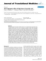
A meniscus is formed by placing liquid argon between
a lower wall and an upper w all, with an opening in the
upper wall as shown in Figure 1a, b. The walls are made
of three layers of platinum (Pt) atoms arranged in fcc
(111) structure. The space above the meniscus is occu-
pied by argon vapor. The domain consists of a total of
14,172 argon atoms and 7,776 platinum atoms. The
initial equilibrium temperatur e is 90 K. The time step is
5 fs. The atomic interaction is governed by the mod ified
Lennard-Jones potential defined as [10]:
Ur
rr r
MLJ
cut
()=
⎛
⎝
⎜
⎞
⎠
⎟
−
⎛
⎝
⎜
⎞
⎠
⎟
⎧
⎨
⎪
⎩
⎪
⎫
⎬
⎪
⎭
⎪
+
⎛
⎝
⎜
⎞
⎠
⎟
−463
12 6
12
rr
r
rrr
cut cut cut cut
⎛
⎝
⎜
⎞
⎠
⎟
⎧
⎨
⎪
⎩
⎪
⎫
⎬
⎪
⎭
⎪
⎛
⎝
⎜
⎞
⎠
⎟
−
⎛
⎝
⎜
⎞
⎠
⎟
−
⎛
⎝
62 12
74
⎜⎜
⎞
⎠
⎟
⎧
⎨
⎪
⎩
⎪
⎫
⎬
⎪
⎭
⎪
⎡
⎣
⎢
⎢
⎤
⎦
⎥
⎥
6
(1)
The above potential form is employed for both Ar-Ar
and Ar-Pt interaction with the following values: s
Ar-Ar
=
3.4 × 10
-10
m, ε
Ar-Ar
=1.67×10
-21
J, s
Ar-Pt
= 3.085 ×
10
-10
m, ε
Ar-Pt
= 0.894 × 10
-21
J.
Thecutoffradiusissetasr
cut
=4s
Ar-Ar
The force of
interaction is calculated from the potential function by
FU=−∇ .
All the boundaries in x and y directions are periodic.
Thewidthoftheperiodicboundaryabovetheupper
walls in the x-direction is restricted to the width of the
opening. Any argon atom which goes above the upper
walls does not interact with the wall atoms anymore.
The top bound ary in the z-d irection is the mirror
boundary condition where the argon atom is reflected
back in the domain without any loss of energy, i.e., the
boundary is adi abatic and elastic in nature. The ‘fluid-
wall thermal equilibrium model’ is used to numerically
simulate heat transfer between wall and fluid atoms
[11,12]. The algorit hm used to calculate the atomic
force interactions is the linked-cell algorithm. The equa-
tions of motion are integrated in order to obtain the
positions and velocities of the atoms at every time step.
The integrator method used here is the Velocity-Verlet
method. Liquid atoms are distinguished from vapor
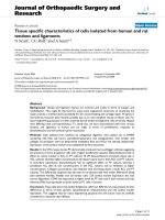
Figure 1 Liquid argon meniscus, surrounded by argon vapor, in an opening constructed of platinum wall atoms. (a) 2D view along the
x-z plane depicting the boundary conditions and dimensions, and (b) 3D view of the simulation domain where the liquid-vapor interface can
be clearly noticeable. Heat is transferred to the meniscus from the platinum wall region shown in red, while the region shown in blue is
maintained at the lower initial temperature.
Maroo and Chung Nanoscale Research Letters 2011, 6:72
/>Page 2 of 7
atoms based on the minimum number o f neighboring
atoms within a certain radius [11]. Vapor pressure is
evaluated as defined elsewhere [13], which has been pre-
viousl y verified by the authors [14]. The simulation pro-
cess is divided into three parts: velocity-scaling period,
equilibration period, and the heating peri od. During the
velocity-scaling period (0-500 ps), the velocity of each
argon atom is scaled at every time step so that the sys-
tem temperature remains constant. This is followed by
the equilibration period (500-1000 ps) in which the
velocity-scaling is removed and the argon atoms are
allowed to m ove freely and equilibrate. The wall tem-
peratures during these two steps are the same as the
initial system temperature. At the start of the heating
period (1000-3000 ps), heat is transferred to the menis-
cus from the platinum wall region and evaporation is
observed. Two cases are simulated in this study:
Case I
After the equilibrium period, the temperature of plati-
num wall underneath the opening (shown i n red color
in Figure 1) is simulated to be 130 K while the rest o f
the wall (shown in blue color in Figure 1) is kept at the
initial temperature of 90 K.
Case II
After the equilibrium period, temperatures of all walls
are simulated to 130 K.
When a liquid film is thin enough, the liquid-vapor
and liquid-solid interfac es interact with each other giv-
ing rise to disjoining pressure. Attractive forces from the
solid act to pull the liquid molecules causing the liquid
film to be at a lower pressure than the surrounding
vapor pressure. A novel method to evaluate the disjoin-
ing forces for nanoscale thin films from molecular
dynamics simulations has been introduced in a prior
study [11]. Starting from the Lennard-Jones potential,
which is the model of interaction between Ar and Pt,
the following equation is derived:
Uz
A
dz d z
LJ
Ar-Pt Ar-Pt
()
() ()
=− − − +
⎡
⎣
⎢
⎢
⎤
⎦
⎥
⎥
12
11
30 30
22
6
8
6
8
(2)
where A is the Hamaker constant, d is the gap
between Ar and Pt slabs, z is the total thickness o f the
Ar slab (including the gap thickness), and U
LJ
is the
total interaction energy between Ar and Pt slabs from
molecular dynamics using LJ potential. This equation
was used to evaluate the Hamaker constant for th e non-
evaporating argon film with varying pressure and tem-
perature [14], and an average value of A = 6.13 × 10
-20
J
is used in this study. The disjoining pressure, for non-
polar molecules, is calculated as:
P
dU z
dz
A
zz
d
LJ
Ar-Pt
=− = −
⎡
⎣
⎢
⎢
⎤
⎦
⎥
⎥
()
() ()
12
28
30
3
6
9
(3)
From the classical capillary equation, the capillary
pressure is the product of interfacial curvature K and
surface tension coefficient s as follows:
PKK
c
==
′′
+
′
()
−
,
.
1
2
15
(4)
where δ’ and δ” are, respectively, the first and second
derivatives of film thickness with respect to x-position.
Equation 4, although a macroscopic formula, serves as a
good approximation [15]. The variation of meniscus
thickness is determined in the x-z plane at different
time intervals. The meniscus, formed from liquid argon
atoms, is divided into square bins of dimension 1s
Ar-Ar
×1s
Ar-Ar
and the number of atoms in each square is
determined. A check is performed from the Pt wall in
the positive z-direction such that if the number of
atoms in a bin falls below 0.5 times the average number
density, an interface marker is placed at the center of
that bin. Interface markers are placed to determine the
meniscus interface using this procedure, and a fourth-
order polynomial fit of these markers is used to obtain
the function δ(x).
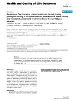
Figure 2 shows the snapshots of the comp utational
domain at different time intervals for Case I and Case
II. For Case I, as shown in Figure 2-Ia, the liquid-vapor
interface of the meniscus is clearly noticeable as eva-
poration has not yet started and surface tension assists
in the formation of the interface. Vigorous evaporation
is seen in Figure 2-Ib which results in an uneven menis-
cus interface. Evaporation rate slows down with time
dueto:(i)anincreaseinpressureinthegasphase,(ii)
majority of liquid atoms at the center of the meniscus
have evaporated, and (iii) liquid meniscus near the
nano-channels is cooler than the vapor temperat ure
causing condensation at the meniscus edges in Case I.
With continuous evaporation taking place, the thinnest
part of the meniscus at the center continues to decrease
in thickness until a uniform non-evaporating film forms
(Figure 2-Id). Unlike Case I, since all walls are at a
higher temperature and liquid argon in the nano-chan-
nels is al so heated up, Case II results in higher evapora-
tion flux and increased mob ility of atoms. Hence, as can
be seen from Figure 2-IId, the non-evaporating film
thickness is greater and the meniscus is less steep in
curvature compared to Case I.
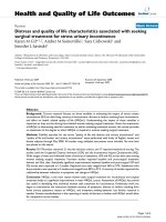
Figure 3a, b shows the disjoining pressure variation
along the width of the meniscus at three different time
steps for Case I and Case II, respectively. Disjoining
pressure increases significantly upon the formation of
Maroo and Chung Nanoscale Research Letters 2011, 6:72
/>Page 3 of 7
the non-evaporating film. The disjoining pressure is
greater for Case I (P
d
=4.34MPa)thanCaseII(P
d
=
1.31 MPa) as expected. Due to higher temperature
throughout the meniscus in Case II, the atoms have
higher freedom to rearrange in a more uniform curva-
tureresultinginanincreaseinfilmthicknessofthe
non-evaporating film at the center of the meniscus com-
pared to Case I.
The disjoining pressure quickly goes down to near-
zero values as the meniscus thickness increases away
from the non-evaporating film region. The capillary
pressure variation is shown in Figure 3c, d for Case I
and Case II, respectively. The capillary pressure is zero
in the non-evaporating region as the non-evaporating
film has a flat interface. A capillary pressure gradient
exists in the meniscus region. Capillary pressure reaches
negative values at the edge of the meniscus due to
curvature effects and is a result of the simulation
domain studied here. Comparing the disjoining and
capillary pressure values , it is seen t hat disjoining forces
dominate in nanoscale ultra-thin films, as related by
Equation 3, while capillary forces become prominent
with increase in film thickness and curvature.
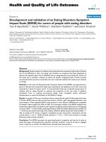
The pressure in the liquid film is obtained using the
augmented Young-Laplace e quation: P
L
= P
v
- P
c
- P
d
,
where P
L
is the liquid pressure and P
v
is the vapor pres-
sure. The average vapor pressure values at t = 2500 ps
for Case I and Case II are 0.613 and 1.071 MPa, respec-
tively. Figure 4a, b depicts the variation in liquid pres-
sure along the meniscus for Case I and Case II,
respectively. Due to high disjoining pressure in the non-
evaporation film region, and partially due to capillary
forces in its adjacent regions, the liquid is found to be
under high negative pressure at the center of the
Figure 2 X-Z plane of simulation domain at different time intervals for Case I and Case II. Evaporation of the liquid meniscus is seen, with
the formation of the non-evaporating film at the center of the meniscus toward the end of the simulation period at t = 2500 ps for both cases.
Maroo and Chung Nanoscale Research Letters 2011, 6:72
/>Page 4 of 7
Disjoining pressure P
d
(MPa)
(a)
Disjoining pressure P
d
(MPa)
(b)
Position along x-direction of meniscus (nm)
Capillary pressure P
c
(MPa)
t = 900 ps
t = 1500 ps
t = 2500 ps
(
c
)
Position along x-direction of meniscus (nm)
Capillary pressure P
c
(MPa)
t = 900 ps
t = 1500 ps
t = 2500 ps
(
d
)
Figure 3 Disjoinin g pressure variat ion in the liquid meniscus for (a) Case I, and (b) Case II, and capillary pressure variation in the
liquid meniscus for (c) Case I, and (d) Case II. Pressure variations are shown at three time intervals of t = 900, 1500, and 2500 ps. Disjoining
forces can be significantly dominant for ultra-thin films at nanoscale compared to capillary forces.
(
a
)(
b
)
Figure 4 Variation in liquid pressure along the meniscus at t = 2500 ps for (a) Case I, and (b) Case II. High negative pressure values are
seen at the center of the meniscus. A normalized function log(Π/δ
ne
) is plotted in the region of negative liquid pressure for Π = R
c
=-2g/P
L
and Π = δ(x), which nullifies the possibility of cavitation in this region as the meniscus thickness is smaller than the critical cavitation radius.
Maroo and Chung Nanoscale Research Letters 2011, 6:72
/>Page 5 of 7
meniscus. Usually, at m acroscale, liquid regions subject
to negative pressures cavitate. However, at nanoscale,
cavitation can be avoided if the critical cavitation radius
is larger than the smallest characteristi c dimension [16].
To verify this aspect in our study, a normalized function
log(Π/δ
ne
) is plotted in the region of negative liquid
pressure for Π = R
c
=-2g/P
L
and Π = δ(x), as shown in
Figure4a,b,whereδ
ne
is the thickness of the non-eva-
porating film. The normalized function has higher
values for Π = R
c
compared to Π = δ(x), which signifies
that the critical cavitation radius is larger than the
meniscus height. Thus, the liquid meniscus region
under high negative pressures can e xist in a metastable
state.
Figure 4 also provides insight into the facto rs which
determine the stability of such films. The difference
between the normalized function values for Π = R
c
and
Π = δ(x) is smaller for Case I than Case II, which
implies that the tendency for the liquid film to rupture
is higher for Case I . The following question arises: what
is the critical thickness δ
cr
at which these liquid films
would rupture, i.e., cavitate? This can be determined
from the definitions of critical cavitation radius and aug-
mented Young-Laplace equation, i.e., δ
cr
=-2g/[P
v
- P
c
(δ
cr
)-P
d
(δ
cr
)]. In the case of non-evaporating films,
which form during heterogeneous bubble growth, this
equation can be simplified by assuming P
c
=0dueto
the planar nature of the film. U sing Equation 3 where
the repulsive term can be neglected as s for liquid-solid
interaction is generally smaller than δ by an order of
magnitude, the following equation can be derived:
6πP
v
δ
3
cr
+12πgδ
2
cr
A = 0, which can be solved analyti-
cally to determine the critical thickness for rupture. It
can be seen that δ
cr
is a function of the vapor pressure,
substrate temperature (indirectly via the liquid-vapor
surface tension term), and substrate-liquid interaction
(embedded in the Hamaker constant A). Premature rup-
ture of non-evaporating film during bubble growth can
lead to significant increase i n pool boiling heat transfer
and delaying the critical heat flux limit.
Negative pressure in liquids has been a point of inter-
est over past several decades. An attempt has been
made in this work to study and quantify the compo-
nents of negative pressures in evaporating nano-men isci
using molecular dynamics simulation. The disjoining
and capillary pressures are evaluated in an evaporating
meniscus at the nanoscale. Disjoining forces significantly
dominate the capillary forces for ultra-thin films at the
nanoscale. Liquid pressure in the meniscus is calculated
using the augmented Young-Laplace equation. The cen-
ter of the meniscus is found to be under high absolute
negative pressures. It is shown that cavitation cannot
occur as the critical cavitation radius is larger than the
thickness of the meniscus. The factors determining the
critical film thickness required for rupture are discussed.
This property of sustaining high negative pressures at
the nanoscale ca n be engineered to prov ide passive
transport of liquid, and applied in power devices to
attain significantly higher heat rejection rates, which is
one of the major bottlenecks in achieving next genera-
tion computer chips, nuclear reactors, and rocket
engines.Thisstudyservesasafirststeptowardunder-
standing pressure characteristics in capillaries at the
nanoscale using molecular simulations, with water
nano-capillaries being the most intriguing and a near
future goal.
Acknowledgements
We acknowledge the partial support by Andrew H. Hines, Jr./Progress Energy
Endowment Fund.
Author details
1
Department of Mechanical and Aerospace Engineering, University of Florida,
Gainesville, FL 32611, USA
2
Department of Mechanical Engineering, M.I.T.,
Cambridge, MA 02139, USA
Authors’ contributions
SCM participated in conceiving the study, wrote the simulation code, carried
out the simulations and results analysis, and drafted the manuscript. JNC
participated in conceiving the study, advised in results analysis and helped
to draft the manuscript. All authors read and approved the final manuscript.
Competing interests
The authors declare that they have no competing interests.
Received: 25 July 2010 Accepted: 12 January 2011
Published: 12 January 2011
References
1. Angell CA: Approaching the limits. Nature 1988, 331:206.
2. Fisher JC: The fracture of liquids. J Appl Phys 1948, 19:1062.
3. Briggs LJ: Maximum superheating of water as a measure of negative
pressure. J Appl Phys 1955, 26:1001.
4. Tas NR, Mela P, Kramer T, Berenschot JW, van den Berg A: Capillarity
induced negative pressure of water plugs in nanochannels. Nano Lett
2003, 3:1537.
5. Yang SH, Nosonovsky M, Zhang H, Chung KH: Nanoscale water
capillary bridges under deeply negative pressure. Chem Phys Lett
2008, 451 :88.
6. Tyree MT: Plant hydraulics: The ascent of water. Nature 2003, 423:923.
7. Nosonovsky M, Bhushan B: Phase behavior of capillary bridges: towards
nanoscale water phase diagram. Phys Chem Chem Phys PCCP 2008,
10:2137.
8. Potash M Jr, Wayner PC Jr: Evaporation from a two-dimensional extended
meniscus. Int J Heat Mass Transfer 1972, 15:1851.
9. Maroo SC, Chung JN: Heat transfer characteristics and pressure variation
in a nanoscale evaporating meniscus. Int J Heat Mass Transfer 2010,
53:3335-3345.
10. Stoddard SD, Ford J: Numerical experiments on the stochastic behavior
of a Lennard-Jones gas system. Phys Rev A 1973, 8:1504.
11. Maroo SC, Chung JN: Molecular dynamic simulation of platinum heater
and associated nano-scale liquid argon film evaporation and colloidal
adsorption characteristics. J Colloid Interface Sci 2008, 328:134.
12. Maroo SC, Chung JN: A novel fluid-wall heat transfer model for
molecular dynamics simulations. J Nanoparticle Res 2010, 12:1913-1924.
13. Weng J, Park S, Lukes JR, Tien C: Molecular dynamics investigation of
thickness effect on liquid films. J Chem Phys 2000, 113:5917-5923.
14. Maroo SC, Chung JN: Nanoscale liquid-vapor phase-change physics in
nonevaporating region at the three-phase contact line. J Appl Phys 2009,
106:064911.
Maroo and Chung Nanoscale Research Letters 2011, 6:72
/>Page 6 of 7
15. Kohonen MM, Christenson HK: Capillary condensation of water between
rinsed mica surfaces. Langmuir 2000, 16:7285-7288.
16. Zhang R, Ikoma Y, Motooka T: Negative capillary-pressure-induced
cavitation probability in nanochannels. Nanotechnology 2010, 21:061057.
doi:10.1186/1556-276X-6-72
Cite this article as: Maroo and Chung: Negative pressure characteristics
of an evaporating meniscus at nanoscale. Nanoscale Research Letters 2011
6:72.
Submit your manuscript to a
journal and benefi t from:
7 Convenient online submission
7 Rigorous peer review
7 Immediate publication on acceptance
7 Open access: articles freely available online
7 High visibility within the fi eld
7 Retaining the copyright to your article
Submit your next manuscript at 7 springeropen.com
Maroo and Chung Nanoscale Research Letters 2011, 6:72
/>Page 7 of 7