METHOD STATEMENTS FOR OFFSHORE PILING WORK OF ACCESS TRESTLE, COAL UNLOADING JETTY AND MOORING DOLPHIN
Bạn đang xem bản rút gọn của tài liệu. Xem và tải ngay bản đầy đủ của tài liệu tại đây (11.27 MB, 114 trang )
Comment Response Sheet (CRS)
Project Title
Van Phong 1 BOT Thermal Power Plant Project
Document Title
METHOD STATEMENTS FOR OFFSHORE PILLING
WORK OF ACCESS TRESTLE, CUJ AND
MOORING DOLPHIN
Document Type
For Approval
Document No
VP1-0-L4-C-GEN-10023
Returned Status
NA
Prepared by
CRS No
VP1-0-L4-C-GEN-10023-B-CRS
CRS Issued Date
08-Jun-2020
Engineer
Construction
Review
Date
Status O/C *
Remarks
No.
1
Section/
Page
1
Owner’s Comment
Response to Comment
16/4/2020
Design of Jetty & Trestle is not yet basically
approved and Test pile is not done at this
stage.This MS must be much revised after Design
& Test pile.
22/5/2020
16/4/2020
O
Noted, DHI is expected submitted document in
parallel time in order to combine with
construction schedule
04/06/2020
C
22/5/2020
16/4/2020
O
DHI has attached on MS Rev.B (Attachment #6)
04/06/2020
C
L4
4/6/2020
Noted
2
3
16/4/2020
Attach the agreed oil spill response plan in further
discussion. The plan will be updated if it is failed
during test pile commencement.
4/6/2020
Closed
Page 1 of 14
Comment Response Sheet (CRS)
3
3
16/4/2020
(1) CVs and qualified certificate of key personnel
be attached but not limited to machinery
certificates.
22/5/2020
16/4/2020
O
(1) Please see construction organization is
shown in Section 5
04/06/2020
O
(2) DHI has revised on MS Rev B Section 7.1.2
16/4/2020
O
- Yes, total blows of each pile driven will be
mention on Record pile driving.
04/06/2020
C
(3) Any approved calculation for welding joint at
site?
(3) All SPP will be fabricated at the factory with
full design length, splicing pile only in case after
driven if pile head level is lower than design
level. Splicing pile is carried out follow WPS
which is qualified by the 3rd party.
16/4/2020
O
04/06/2020
O
4/6/2020
(3) Open- if having site welding, calculation to be
attached.
11/6/2020
4/6/2020
(1) Qualified personnel certificate to be shown
since offshore piling work is critical.
4
3
(2) Pile marking: the marking range should be
10cm for last 05m of the pile head segment. Total
blows will be recorded?
11/6/2020
Personnel certificate for piling work don’t
requirement, but experience person is
importance so please see attachment 8 for more
information.
4/6/2020
(2) Closed
3
Welding joint at the site will be conducted as
attachment 5 and it is qualified by third party, a
sample mock up shall be implement with test
prior construction to ensure quality of welding
joint is equal or higher than quality of SPP’s
material
(3) Noted
Page 2 of 14
Comment Response Sheet (CRS)
5
6
3
3
(4) Pile numbering to be shown for driving
sequence with approved coordinates.
(4) Pile numbering is shown in drawing VP1-0L4-C-UZR-05523
4/6/2020
(4) Not address the concern.
11/6/2020
Pile numbering and driving sequence are shown
in attachment 1 (based on axis of pile), piling
report shall follow it.
(5) Indicate the standard installation tolerances to
be applied.
(6) Add procedure to record the rebound via
graphical re-bounce (see TSPHF requirement).
(5) Installation tolerances to be applied is
Specification Section 9.8.4.1 and
TCVN10318:2014 - Steel pipe piles and stel pipe
sheet piles for port harbour - Specification for
construction and acceptance
4/6/2020
(5)(6) Closed
7
3
(7) In typical section pls show the pile with the
splicing location added in.
4/6/2020
(7) refer to (3)
8
4
16/4/2020
Seabed elevation
16/4/2020
O
04/06/2020
O
Noted
16/4/2020
O
04/06/2020
C
(7) The splicing location is shown in Figure 8-7
16/4/2020
O
11/6/2020
04/06/2020
O
(6) DHI Has revised and updated on MS Rev B
(Section 8.2)
Welding joint at the site will be conducted as
attachment 5 and it is qualified by third party, a
sample mock up shall be implement with test
prior construction to ensure quality of welding
joint is equal or higher than quality of SPP’s
material
(7)
Noted
22/5/2020
16/4/2020
O
Yes, the bottom elevation is the sea bed
04/06/2020
C
4/6/2020
Noted
Page 3 of 14
Comment Response Sheet (CRS)
9
4
16/4/2020
This is Access Road?
22/5/2020
16/4/2020
O
Yes, the technological trench is access road
04/06/2020
C
22/5/2020
16/4/2020
O
The general plan is not changed and same with
this drawing.
04/06/2020
C
22/5/2020
16/4/2020
O
Noted, The construction will be started when
drawings are approved by owner and consultant
04/06/2020
C
22/5/2020
16/4/2020
O
OCDI and JRA standard is included
04/06/2020
Closed
O
22/5/2020
16/4/2020
O
Noted, These will be revised after approval of
design
04/06/2020
C
4/6/2020
Noted
10
4
16/4/2020
This drawing is very old.
Undated Plot Plan should be used.
4/6/2020
Closed
11
4
16/4/2020
These drawings are not yet basically approved.
4/6/2020
Closed
12
5
16/4/2020
Is OCDI and JRA standard included?
4/6/2020
OPEN
Not add yet.
13
5
16/4/2020
These shall be revised after approval of design.
4/6/2020
Closed
09/6/2020
DHI has revised and updated on MS Rev C
Section 1.1.2
Page 4 of 14
Comment Response Sheet (CRS)
14
7
16/4/2020
Please detail any solutions to prevent steel piles
rotation, movement due to the barge is inclined
plane condition during shipping, loading and
unloading activities (serious accident can be
happened due to steel pile rotation)
22/5/2020
16/4/2020
O
DHI has revised and updated on MS Rev B
Section 7.1.2
04/06/2020
C
16/4/2020
Splicing piles should be executed at Factory from
QC of welding. On barge, there is sway and
wind/rain.
22/5/2020
16/4/2020
O
All SPP will be fabricated at the factory with full
design length, splicing pile only in case if the pile
head level is lower than design level. Splicing
pile is carried out follow WPS which is qualified
by the 3rd party.
04/06/2020
C
Anti-corrosion coating for splash zone is not
stated, and this should be also fabricated at
Factory.
Nippon Steel has very good Anti-corrosion coating
system.
Anti-corrosion coating for splash zone is
described on MS Rev B Section 7.1.1
22/5/2020
16/4/2020
O
Noted, but splicing will not do at Factory
04/06/2020
C
4/6/2020
Closed
15
8
Noted
4/6/2020
Closed
16
10
16/4/2020
When splicing pile at Factory,
this is also needed.
4/6/2020
Closed
Page 5 of 14
Comment Response Sheet (CRS)
17
10
16/4/2020
Please describe how to keep floating barge
balance during loading or unloading the piles?
4/6/2020
OPEN. Please reflect it in this document for site
implementation and provide the clue for review
18
11
16/4/2020
What is falling prevention while welding on the
round surface & rotating pile?
22/5/2020
16/4/2020
O
The pile will be load from the center to both side
of stock barge, unloading pile on floating barge
will be same as sequence of loading.
04/06/2020
O
The crane for loading and unloading will be fix on
the barge during operation.
Closed
9/6/2020
DHI has revised and updated on MS Rev B
(Section 7.4)
22/5/2020
16/4/2020
O
This picture is for refer only, all activity will be
followed safety regulations
04/06/2020
C
22/5/2020
16/4/2020
O
This accuracy 2cm guarantees for the pile
position is acceptable, specification tolerance of
project is 15cm (Part III-2 Exhibit B1 Tech Spec
Section 9, item 9.8 Piling).
04/06/2020
C
22/5/2020
16/4/2020
O
The condition to stop driving when the pile be
achieved the design rebound
04/06/2020
C
4/6/2020
Closed
19
11
16/4/2020
This accuracy 2cm may be too large.
Can this accuracy be adjusted by Total Station
method?
4/6/2020
Closed
20
16
16/4/2020
There is no requirement of anchoring depth to
hard rock layer?
4/6/2020
Closed
Page 6 of 14
Comment Response Sheet (CRS)
21
17
16/4/2020
What is the fall prevention for these people?
4/6/2020
Closed
22
23
18
19
16/4/2020
What is countermeasure to prevent the barge
inclined during loading and slot the steel pile to
the hammer?
22/5/2020
16/4/2020
O
This picture is for refer only, all activity will be
followed safety regulations
04/06/2020
C
22/5/2020
16/4/2020
O
According to Inspection certificate of Pilling Rig,
the capacity of piling rig can reach 20m and
lifting capacity is 60T. According to Certificate of
technical safety and environmental protection,
The barge PX17 carry the pilling rig. So loading
and slot the steel pile which the pile weight under
lifting capacity is safety
04/06/2020
O
Closed
4/6/2020
OPEN
It is recommended to provide the racks or welded
stopper to prevent the rotation of the piles due to
inclined barge condition
11/6/2020
16/4/2020
This shall be revised according to design and test
pile result.
22/5/2020
16/4/2020
O
DHI has revised and updated on MS Rev B
section 8.1
04/06/2020
C
22/5/2020
16/4/2020
O
Noted, These drawing will be revised after
approval of design
04/06/2020
C
Noted, The solution has been mention on section
7.1.2 ( MS Rev C)
4/6/2020
Closed
24
19
16/4/2020
These drawing should be revised after approval of
design.
4/6/2020
Closed
Page 7 of 14
Comment Response Sheet (CRS)
25
20
16/4/2020
After driving pile at least 3m where is drilled,
continue to drive pile into 10~20cm more as
possible.
22/5/2020
16/4/2020
O
DHI has revised on MS for driving pile Rev B
(drilling method will not apply for piling work)
04/06/2020
C
22/5/2020
16/4/2020
O
DHI has revised and updated on MS rev B which
doesn’t use drilling machine.
04/06/2020
C
22/5/2020
16/4/2020
O
DHI has revised and updated on MS rev B which
doesn’t use drilling machine.
04/06/2020
C
4/6/2020
Closed
26
21
16/4/2020
How to know that the drilling machine is stable
and safe to operation on the barge? Are there any
confirmation from authority? What to do with the
soil generated?
4/6/2020
Closed
27
21
16/4/2020
Please show the toe of Drill, especially Drill Bit.
4/6/2020
Closed
Page 8 of 14
Comment Response Sheet (CRS)
28
21
16/4/2020
Please detail bracing installation. what is the
hazard in this task? what is the risk? What is the
method for this task? how to make sure people
involved in this task are safe, how to prevent
people falling down into the hole of steel pile?
4/6/2020
OPEN
There is nothing revised at the section 9. Please
detail how to fix the plywood covering the open
holes with the piles to prevent plywood fly away
and please reflect it in this document for site
implementation
29
23
16/4/2020
Describe how to keep the pile head stable/not
hitch right after cut-off? How to prevent people
falling down into the hole of steel pile?
4/6/2020
Please detail how to fix the plywood covering the
open holes with the piles to prevent plywood fly
away and please reflect it in this document for site
implementation
22/5/2020
16/4/2020
O
DHI has revised and updated on MS Rev B
(section 9)
04/06/2020
O
All head pile will be cover by plywood plate to
prevent people falling down into the hole of steel
pile. And others active will be followed safety
regulation.
Closed
11/6/2020
DHI has revised and updated on MS Rev B
(section 9)
The plywood covering is fix to pile head by
plywood panels which is fixed under the plywood
covering and inside the pile.
22/5/2020
16/4/2020
O
DHI has revised on MS Rev B section 9.3. All
head pile will be cover by plywood plate to
prevent people falling down into the hole of steel
pile
04/06/2020
O
Closed
11/6/2020
The plywood covering is fix to pile head by
plywood panels which is fixed under the plywood
covering and inside the pile.
Page 9 of 14
Comment Response Sheet (CRS)
30
25
16/4/2020
This tolerance is practically difficult, and the
counter measure should be considered when over
the tolerance.
22/5/2020
16/4/2020
O
DHI has revised and updated on MS Reb B
Section 11.4.2, countermeasure will be
considered and updated later
04/06/2020
C
22/5/2020
16/4/2020
O
Please refer to document “VP1-EPC-L4-H-GEN00006” and check in attachment 7 for refer.
04/06/2020
C
22/5/2020
16/4/2020
O
Please refer to document “VP1-0-EPC-H-GEN00001”
04/06/2020
C
22/5/2020
16/4/2020
O
DHI has revised and updated the new version on
MS Rev B(attachment 1)
04/06/2020
C
22/5/2020
16/4/2020
O
DHI’s EHS will be inspected all equipment and
make sure it is safety when its operate, in this
case drilling machine will not use on MS Rev B
04/06/2020
C
4/6/2020
Closed
31
28
16/4/2020
Please lease link/reference to the approved "Work
over or close water procedure".
4/6/2020
Closed
32
28
16/4/2020
Please link/reference to the approved "EPRP of
EPC contractor".
4/6/2020
Closed
33
30
16/4/2020
This also should be revised after approval of
design.
4/6/2020
Closed
34
30
Drawing 6
16/4/2020
are there any confirmation from authority or third
party that the drilling machine is safe/ stable for
operation on the barge?
4/6/2020
Closed
Page 10 of 14
Comment Response Sheet (CRS)
35
30
Drawing 6
16/4/2020
are there any confirmation from authority or third
party that the crane is safe/ stable for operation on
the barge?
4/6/2020
Closed
36
30
Drawing 7
16/4/2020
As your confirmation on the document No VP1-0L4-C-GEN-10014-B-CRS that this equipment is
movable platform. Please prepare all the
documents based on Vietnamese regulation such
as TCVN 5316:2006, and other requirements prior
to operation on site.
22/5/2020
16/4/2020
O
According to EHS inspection and Certificate of
technical safety and environmental protection
which are confirmed that crane is safe/ stable for
operation on the barge.
04/06/2020
C
22/5/2020
16/4/2020
O
Noted, all the documents will be prepare prior to
operation on site.
04/06/2020
C
22/5/2020
16/4/2020
O
Pontoon will be used to install bracing system
and barricade
04/06/2020
C
22/5/2020
16/4/2020
O
DHI has revised and updated on MS Rev
B(attachment 03)
04/06/2020
C
4/6/2020
Closed
37
30
Drawing 12
16/4/2020
Please describe detail how to arrange bracing and
barricade
4/6/2020
Closed
38
32
Page 9/9
16/4/2020
Why this matrix is not in compliance with
Doosan's risk management procedure?
4/6/2020
Closed
Page 11 of 14
Comment Response Sheet (CRS)
39
32
Page 9/9
16/4/2020
Did Doosan's HSE team check this document?
Why this Risk assessment is not compliance with
Doosan's risk assessment procedure?
The content of this risk assessment is not enough
( there are no steps of bracing installation, pile
head cut off, how to remove the pile head cut off?
no information of JSA, No hazard identification on
barge inclined condition, pile rotation.
22/5/2020
16/4/2020
O
Noted, Doosan’s HSE team has checked this
document, it has revised on MS rev
B(attachment 3)
04/06/2020
C
22/5/2020
16/4/2020
O
DHI revised and updated on MS rev B
04/06/2020
C
11/6/2020
04/06/2020
Closed
O
04/06/2020
Closed
O
04/06/2020
Closed
O
4/6/2020
Closed
40
33
Page 01/02
16/4/2020
Seem the proposed WPS is not feasible, please
check and confirm.
4/6/2020
Closed
41
5
OCDI and JRA Standard. are added.
DHI has revised and updated on MS Rev C
Section 1.1.2
42
43
5
5
The MS do not cover drilling of pile, please
update accordingly.
11/6/2020
Pile length should be shown
11/6/2020
DHI has revised and updated on MS Rev C
Section 2
DHI has revised and updated on MS Rev C
Section 3
Page 12 of 14
Comment Response Sheet (CRS)
44
45
46
47
48
7
9
14
16
17
Full design length of pile is fabricated at
Manufacturer and then transported to Site by
Barge ? If it is, clearly stated.
11/6/2020
The racked pile location is variable base on the
level, how to setting out the coordinate at tide
level?
11/6/2020
How much the design rebound, please make clear
to guild the site work.
11/6/2020
There is only one condition to stop driving. How
about if rebound is less than design rebound but
pile tip not reach to design level yet?
11/6/2020
How many meter is the segment?
11/6/2020
04/06/2020
Closed
O
04/06/2020
Closed
O
04/06/2020
Closed
O
04/06/2020
Closed
O
04/06/2020
Closed
O
Yes, full design length of pile will fabricate at
manufacture and then transport to site by barge
(see Section 7.1.2)
GPS system will be set up the Zero Plan by the
intersection between the center of the Barge’s
longitudinal and turning point of the piling rack.
When the tide level change and inclined angle of
pile is not change, the software base on Zero
plan to calculate the tolerance of coordinate and
elevation at the measurement point between
actual and design.
Rebound will combined with design approval,
now we submitted the design rebound is 0.6mm
for Jetty and 1.2mm for Access trestle
Yes, Pile driving will be stopped when rebound
equal or less than design rebound.
DHI will fabricate 10m pile segment which is
produced and coated in factory, at site based on
actual elevation of top pile, pile segment will be
cut off by cutting machine for splicing
Page 13 of 14
Comment Response Sheet (CRS)
49
50
51
21
22
Attachment
2
Is this for NPV Coating? Specification of NPV
coating should be shown.
11/6/2020
100mm for boundary pile and 150mm for inside
pile is recommended
11/6/2020
Design of Jetty is not completed and approved
yet. All Schedule should be revised.
11/6/2020
04/06/2020
Closed
O
04/06/2020
Closed
O
04/06/2020
Closed
O
Yes, this is for NPV Coating, Specification of
NPV coating has been submitted on document:
VP1-0-L4-Q-GEN-10050-A Material
Info.Sub.Coating Steel Pipe Pile CUJ_PE
Noted, It is complied with Project Specification
Section 9.8.4.1 the tolerances of pile head
DHI has revised and updated on MS Rev C with
expect date can get approve design of jetty.
Additional Notes (if any)
* O - Open, C – Closed
Page 14 of 14
AP
APPROVED
Approved
AC
APPROVED WITH COMMENT
Contractor to revise the correction and resubmit
NA
NOT APPROVED
Revise the correction and resubmit before proceeding
REVIEWED
For Approval
RE
Information acknowledged with no comment
RC
REVIEWED WITH COMMENT
Information acknowledged with comments
Note: Approval or comment does not relieve the Contractor of
all obligations covered under contract
Discipline: Civil
22 Jun 20
Date:
C
11-Jun-2020
For Approval
J.H CHOI
K.S KIM
D.S YU
B
22-May-2020
For Approval
J.H CHOI
K.S KIM
D.S YU
A
07-Apr-2020
For Approval
J.H CHOI
K.S KIM
E.T KIM
REV
DATE
DESCRIPTION
Approved
Checked
Prepared
OWNER
VAN PHONG POWER COMPANY LIMITED
PROJECT
Van Phong 1 BOT Thermal Power Plant Project
Status
□Approved
□Approved with Comment
□Not Approved
□Reviewed
OWNER’S ENGINEER
Pöyry Switzerland Ltd.
EPC CONTRACTORS
IHI–TESSC–CTCI–DHI CONSORTIUM
PROJECT DOCUMENT No
REV
VP1-0-L4-C-GEN-10023
C
DOCUMENT TITLE
METHOD STATEMENTS FOR OFFSHORE PILLING WORK OF ACCESS TRESTLE, COAL
UNLOADING JETTY AND MOORING DOLPHIN
EPC
EPC DOCUMENT No.
VP1-0-L4-C-GEN-10023
Doosan Heavy Industries and Construction
REV
C
Page | 1
VAN PHONG 1 BOT THERMAL POWER PLANT
PROJECT
TABLE OF CONTENTS
PAGE
TABLE OF CONTENTS .................................................................................................................................... 2
1.
GENERAL .................................................................................................................................................. 4
1.1.
INTRODUCE ...................................................................................................................................... 4
1.1.1.
DRAWINGS AND DOCUMENTS ............................................................................................................. 4
1.1.2.
CODE AND STANDARDS ..................................................................................................................... 5
2.
SCOPE OF WORK ................................................................................................................................... 5
3.
QUANTITY OF PILE .................................................................................................................................. 5
4.
SCHEDULE ................................................................................................................................................ 6
5.
CONSTRUCTION ORGANIZATION ......................................................................................................... 6
6.
MANPOWER AND EQUIPMENT MOBILIZATION PLAN FOR OFFSHORE PILING WORK ................. 6
6.1.
6.2.
7.
EQUIPMENT MOBILIZATION PLAN ............................................................................................................ 6
MANPOWER MOBILIZATION PLAN ............................................................................................................ 7
METHODOLOGY ....................................................................................................................................... 7
7.1.
7.1.1.
7.1.2.
7.2.
7.2.1.
7.2.2.
7.3.
7.4.
7.5.
8.
PILE PREPARATION ............................................................................................................................... 7
PILE PRODUCTION ............................................................................................................................ 7
STOCK PILING AND TRANSPORTATION OF PILES FOR OFFSHORE PILLING WORK .................................... 8
SETTING OUT THE COORDINATE ............................................................................................................. 9
SETTING OUT THE COORDINATE BY GPS SYSTEM: .............................................................................. 9
SETTING OUT THE COORDINATE BY TOTAL STATION: .......................................................................... 10
MOVING AND MOORING TOWER DRIVING BARGE TO PILLING LOCATION ................................................... 12
PILE RIGGING AND HOISTING................................................................................................................ 13
SELECT THE HAMMER ......................................................................................................................... 14
PILE DRIVING FOR ACCESS TRESTLE AND COAL JETTY ............................................................... 14
8.1.
8.2.
-
9.
GENERAL FOR PILE DRIVING ................................................................................................................ 14
DRIVING PILE ...................................................................................................................................... 15
PREPARATION ........................................................................................................................................ 18
CLEANING THE PILE HEAD PRIOR TO WELDING .......................................................................................... 18
LOCATING THE PILE PRIOR TO WELDING ................................................................................................... 18
WELDING TO JOIN THE PILE SEGMENTS .................................................................................................... 18
COMPLETION WORK ............................................................................................................................. 19
9.1.
9.2.
9.3.
10.
BRACING DERIVED PILE HEAD .............................................................................................................. 19
PDA (PILE DYNAMIC ANALYZER) TEST PILE.......................................................................................... 20
PILE HEAD TREATMENT ....................................................................................................................... 21
REPAIR AND TOUCH-UP PROCEDURE ........................................................................................... 21
10.1.
10.2.
11.
QUALITY CONTROL ........................................................................................................................... 22
11.1.
11.2.
11.3.
11.4.
11.4.1.
11.4.2.
11.4.3.
11.4.4.
12.
SURFACE PREPARATION.................................................................................................................. 21
PAINTING APPLICATION ................................................................................................................... 21
QUALITY CONTROL OF MATERIALS .................................................................................................. 22
QUALITY CONTROL OF MATERIALS HANDLING & DELIVERIES ............................................................. 22
QUALITY CONTROL OF MATERIALS STORAGE ................................................................................... 22
QUALITY CONTROL OF PILE DRIVING PROCESS ................................................................................ 22
QUALITY CONTROL OF W ELDING ..................................................................................................... 22
TOLERANCES ................................................................................................................................. 23
RECORDING ................................................................................................................................... 23
FIELD SPLICING .............................................................................................................................. 23
ENVIRONMENT , HEALTH AND SAFETY ORGANIZATION ............................................................ 24
2|Page
VAN PHONG 1 BOT THERMAL POWER PLANT
PROJECT
12.1.
12.1.1.
12.1.2.
12.1.3.
12.1.4.
12.2.
12.2.1.
12.2.2.
GENERAL SAFETY PROCEDURES ..................................................................................................... 24
FLOATING PLANT & EQUIPMENT ...................................................................................................... 24
INSPECTION OF LIFE-SAVING AND SAFETY EQUIPMENT ....................................................................... 24
PILLING W ORKS.............................................................................................................................. 24
W ORK OVER W ATER ...................................................................................................................... 24
SITE SITUATION RESPONSE AND EMERGENCY RESPONSE ................................................................ 25
SITE RESPONSE ............................................................................................................................. 25
EMERGENCY AND CONTACT INFORMATION........................................................................................ 25
13.
ATTACHMENT .................................................................................................................................... 25
ATTACHMENT 01: DRAWING OF MS FOR PILE DRIVING ...................................................................... 25
ATTACHMENT 02: SCHEDULE OF PILLING WORK ................................................................................ 25
ATTACHMENT 03: RISK ASSESSMENT .................................................................................................. 25
ATTACHMENT 04: PERSONEL FOR PILE JOINT WELDING .................................................................... 25
ATTACHMENT 05: CERTIFICATION OF WELDING WIRE SF-71 .............................................................. 25
ATTACHMENT 06: COUNTERMEASURE TO PREVENT OIL LEAKS DURING DRIVING PILES ................. 25
ATTACHMENT 07: WORK OVER WATER ............................................................................................... 25
ATTACHMENT 08: EXPERIENCE PERSONNEL FOR PILING WORKS ...................................................... 25
3|Page
VAN PHONG 1 BOT THERMAL POWER PLANT
PROJECT
1. GENERAL
1.1. INTRODUCE
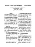
The location of Van Phong 1 BOT Thermal Power Plant is chosen to be in Van Phong bay and
contiguous to My Giang transshipment and petrol entrepot warehouse area
+ The length of trestle is about 1150m with the width of trestle is 12m; from axis 44 to axis
48 the width of trestle is 17m. Above the trestle is technological trench with the width is 5m and
from axis 44 to axis 48 is 10m.
+ The dimension of coal unloading Jetty is: LxB = (297.5x27)m; crest elevation: +6.50m;
bottom elevation: -18.31m
+ The dimensions of 02 mooring dolphin are: LxBxH = (12x12x2)m; crest elevation:
+6.50m; bottom elevation: -18.31m
This document provides method statement for offshore pilling work for trestle, coal unloading jetty
and mooring that belong to Van Phong 1 BOT thermal power plant. The works under this
method comprise the storage, transportation, lifting, driving, connection for all piles within
Scope of Work.
The piles are steel pipe piles installed by driving to the specified levels that are in accordance with
approved specification and approved construction drawings.
Figure 1-1 General view of Trestle and coal unloading jetty
1.1.1. Drawings and documents
Latest version of following documents will be referred to:
- General: From VP1-0-L4-C-UZN-05101 to VP1-0-L4-C-UZN-05103
- Drawings of Jetty: From VP1-0-L4-C-UZN-05104 to VP1-0-L4-C-UZN-05137
- Drawings of Trestle: From VP1-0-L4-C-UZN-05501 to VP1-0-L4-C-UZN-05526
And documents as following:
4|Page
VAN PHONG 1 BOT THERMAL POWER PLANT
PROJECT
- Part III-2 Exhibit B1 Tech Spec Section 8, item 8.7 Steel work
- Part III-2 Exhibit B1 Tech Spec Section 8, item 8.8.2 Piling
- Part III-2 Exhibit B1 Tech Spec Section 9, item 9.8 Piling
1.1.2. Code and standards
-
QCVN 02 - 2009/BXD National technical regulation on data of natural conditions used in the
construction;
TCVN 10667:2014 About centrifugal concrete piles - Drilling and lowering piles Construction and acceptance.
TCVN 9394:2012 About pile driving and piling - Construction and acceptance
ASTM D1143: Standard Test Methods for Deep Foundations Under Static Axial
Compressive Load
ASTM D3689: Standard Test Methods for Deep Foundations Under Static Axial Tensile
Load
ASTM D3966: Standard Test Methods for Deep Foundations Under Lateral Load
British Standard Code of Practice for Maritime Structures (BS 6349)
AISC standard : American Institute of Steel Construction;
JIS standard : Japanese Industrial Standards (Including OCDI and JRA Standard)
-
C
-
2. SCOPE OF WORK
This method statement covers all construction aspects for offshore piling work for trestle, Coal
unloading jetty and Mooring. This method statement deals with the followings
- Method for storage and transportation of piles to the working area.
- Method for connection of pile segments
- Method for setting out of piles
- Method for lifting and driving of piles.
3. QUANTITY OF PILE
C
Summary quantity of offshore piles location of trestle is shown in the following table
No.
1
2
3
5|Page
Items
Coal Jetty
Mooring
Dolphin
Trestle
16
Length
(m)
34
Vertical SPP
1000
16
34
Rake SPP
1000
16
36
Vertical SPP
Rake SPP
Quantity
(nos)
Diameter
(mm)
Thickness
(mm)
30
1000
12
221
Remark
82
1000
16
36
6
16
33
Vertical SPP
7
1000
1000
16
33
Rake SPP
6
1000
16
36
Vertical SPP
7
1000
16
36
Rake SPP
Vertical SPP
9
1000
14
28
2
1000
14
30
6
1000
14
30.5
Vertical SPP
Rake SPP
32
1000
14
32.5
Rake SPP
16
1000
14
33.5
Rake SPP
VAN PHONG 1 BOT THERMAL POWER PLANT
PROJECT
C
No.
Items
14
Length
(m)
35.5
Rake SPP
14
36
Rake SPP
Quantity
(nos)
Diameter
(mm)
Thickness
(mm)
18
1000
176
1000
Remark
Table 3-1 Quantities of pile location
4. SCHEDULE
Detail schedule shall be shown on Attachment – 02
5. CONSTRUCTION ORGANIZATION
Figure 5-1 Construction organization
6. MANPOWER AND EQUIPMENT MOBILIZATION PLAN FOR OFFSHORE PILING
WORK
6.1. Equipment mobilization plan
Main equipment are shown on table as below:
6|Page
VAN PHONG 1 BOT THERMAL POWER PLANT
PROJECT
No.
I
Type of equipment
Technical data
Name of
equipment
Description work
Phu Xuan 17
Driving Mass Pile
Test Pile works and Mass pile for Trestle
1
Pile Driving Barge
1170T
2
Diesel hammer
12.8T
3
Crane on Barge 90T
1000T
Phu Xuan 10
Support for pile
driving work
4
Barge for load pile
1000T
Truong Thanh
168
Loading pile
5
Tug boat
350CV
Phu Xuan 03
Support for pile
driving work
Phu Xuan 20
Driving Mass Pile
II
Driving Mass Pile
Coal unloading jetty and Mooring Dolphin
1
Pile driving Barge
350T
2
Diesel hammer
12.8T
3
Barge for load pile
1000T
Phu Xuan 07
Loading pile
4
Tug boat
650CV
Hung Phu 39
Support for pile
driving work
Driving Mass Pile
Table 6-1 List of equipment for piling work
6.2. Manpower mobilization plan
No.
Description
Unit
Quantity
1
Site manager
Person
1
2
Site Engineer
Person
2
3
Foreman
Person
2
4
Operator
Person
25
5
Worker
Person
15
6
HSE
Person
2
Remark
The manpower
will be adjusted in
accordance with
the construction
Table 6-2 List of manpower for piling work
7. METHODOLOGY
7.1. Pile preparation
7.1.1. Pile Production
In general, Piles Production will be carried out in the manufacturer’s plant and all raw
materials necessary for the production shall be tested in accordance with the applicable
standard, testing procedure, criteria and frequency. During the production stage, an In-Process
inspection shall be carried-out frequently regularly to ascertain that manufacturing process are in
compliance with the applicable standard and quality requirements. Manufacturing records shall
be kept updated and maintained throughout the completion of production.
7|Page
VAN PHONG 1 BOT THERMAL POWER PLANT
PROJECT
C
Steel pipe pile will be protected by cover painting which will be perform in factory of NPV
coating.
7.1.2. Stock piling and transportation of Piles for offshore pilling work
Full design length of steel pipe pile is fabricated at Manufacturer and then transported to
Site by Barge. During transportation and storage on barge all pile will be installed the lashing
straps and wooden millet between piles to prevent rotation and painting scratch.
Figure 7-1 Lashing between piles
Steel pipe pile shall be carried out in the factory before being loaded on the barge and the
pile surface shall be inspected and accepted after arriving at the construction site.
After receiving the steel pipe pile from the supplier, the contractor shall inform the owner and
consultant to inspect the quality and specifications of all piles such as length, diameter,
thickness… any pile that doesn’t meet the technical requirement shall be rejected and remove
immediately from the construction site. All piles that meet the specification requirements shall be
marked in accordance with technical instruction.
The Manufacturer's Certificate must include detailed information of the pile as required by the
Technical Instructions.
The pile shall be painted to mark the length along the length of the pile, the marking range is
10cm for 05m of the pile head segment and 0.5m for pile segment remain.
After being inspected by owner and owner’s engineer, the qualified piles shall be transported
to the pile driving position.
8|Page
VAN PHONG 1 BOT THERMAL POWER PLANT
PROJECT
Pile Reject
Pile Fabrication
Approval
for deliver
Deliver to site
Approval
for driving
Inspection by
owner and
conssultant
Figure 7-2 Diagram of pile inspection of the manufacture
+ The SSP shall stocked at storage barge
+ The pile segments shall be transferred from the transportation barge to the storage barge
as shown in the diagram of pile loading below
Figure 7-3 Diagram of pile loading from the transportation barge to the storage barge
7.2. Setting out the coordinate
7.2.1. Setting out the coordinate by GPS system:
The high technology survey system (GPS) will be used for setting the pile location before
driving the piles to ensure and maintain the accuracy for every pile driven. It also use for checking
and calculating the top elevation of the pile.
The position of pile will be surveyed following the below step:
+ The GPS fixed station will be set up on the land area which is the origin coordinates.
+ Firstly: This place should within 15 degree above the horizontal plane without or only little
obstruction
+ Secondly: Without any power full electromagnetic wave source within 200m
+ Thirdly: This place shall be in a higher location to ensure the GPS system can work
efficiency.
After setting up the fixed station, mobile station can be set up on the existing other control
benchmark, and transfer the parameter by the static method, and then input the parameters to
GPS system and by the Real Time Kinematic (RTK) operation method to calculate the control
reference point, and then compare with the existing data to justify the correctness of parameter.
The measure sequence is as follow:
9|Page
VAN PHONG 1 BOT THERMAL POWER PLANT
PROJECT
Measuring the relevant location between the main working point and GPS location, and
then will get the pile location relative to the working point according to the pile body slop ratio, pile
center distance, pile top elevation and pile location coordinate, and then install the pile.
The pile elevation and set also can be controlled and calculated by GPS system.
The contractor will survey the position of pile at locating oile and at cut-off pile head. The
survey instrument at locating pile is GPS on the floating pile driving. The survey team will check the
position pile head cut – off used GPS.
The achievable accuracy of GPS is 2cm.
For the Raked pile with angle
For the Raked pile with rotation angle is determined by = arc tan(1/n) (n is pile body
slope), to eliminate the influence of the angle deviation, tilt sensors are installed on the pile rack to
measure the actual angle and correct the final deviation. Raked pile with angle has main impact
on the pile ship longitudinal axis distance, upward view as shown, slope angles take positive,
otherwise take negative.
Figure 7-4 GPS survey equipment
7.2.2. Setting out the coordinate by total station:
Using total station and gradient to determine coordinates, the elevation of the pile head and
follow during the driving process.
For Vertical pile: Center of the pile shall be located by 2 total stations with the method of aiming at
the concave mirror at the position of pile wall. During pile driving process, coordinates of the pile
shall be controlled by multiple points along the pile axis.
10 | P a g e
VAN PHONG 1 BOT THERMAL POWER PLANT
PROJECT
Figure 7-5 Position of vertical pile
For the raked pile with the rotation angle:
According to the manufacturing feature, because the hammer rig is fixed on the pile driving
barge, so the rotation of the barge is just the rotation of the pile. When locating the center of the
raked pile, using 2 total stations (Total station 1 and total station 2), in which, one used for locating
and controlling center of the pile and one used for adjusting the rotation of pile.
In order to adjust the rotation of pile, it’s required to aim the second point on the pile driving
barge. Accordingly, welding a fixed picket at the aft section so as to coincide with the longitudinal
axis of the pile driving barge; The distance from the picket to the hammer axis (that is pile center) is
a measured constant. Determining coordinates of the picket based on design coordinates of each
respective steel pile, this work is performed on the file AutoCAD and shall be carried out in
advance so as not to affect the pile driving progress.
The sequence of locating raked pile:
+ Locating the center of the raked pile by Total station 1 as described in details on the drawing.
+ After locating the center of the pile into the designed coordinates and required rake; the pile
driving barge shall be roasted by a 6 winches system with rotation center is center of the pile until
the picket coincides with the direction of Total station 2; then the pile is rotated to the right rotation
angle as required.
+ It is noted that when rotating the pile driving barge with the rotation axis is center of the pile,
the center of the pile (hanging on the rig) may be slipped out of the coordinates; then, it’s required
to combine both total stations to relocate the pile to the original position; All information shall be
exchanged via walkie-talkie system with operating radius > 1000m.
11 | P a g e