METHOD STATEMENT FOR BOILER FOUNDATION UNIT 2
Bạn đang xem bản rút gọn của tài liệu. Xem và tải ngay bản đầy đủ của tài liệu tại đây (13 MB, 91 trang )
AP
APPROVED
Approved
AC
APPROVED WITH COMMENT
Contractor to revise the correction and resubmit
NA
NOT APPROVED
Revise the correction and resubmit before proceeding
RE
REVIEWED
Information acknowledged with no comment
For Approval
RC
REVIEWED WITH COMMENT
Information acknowledged with comments
Note: Approval or comment does not relieve the Contractor of
all obligations covered under contract
Discipline: Civil
15 Jul 20
Date:
A
02-Jul-2020
For Approval
J.H CHOI
K.S KIM
D.H JEONG
REV
DATE
DESCRIPTION
Approved
Checked
Prepared
OWNER
VAN PHONG POWER COMPANY LIMITED
PROJECT
Van Phong 1 BOT Thermal Power Plant Project
Status
□Approved
□Approved with Comment
□Not Approved
□Reviewed
OWNER’S ENGINEER
Pöyry Switzerland Ltd.
EPC CONTRACTORS
IHI–TESSC–CTCI–DHI CONSORTIUM
PROJECT DOCUMENT No
REV
VP1-2-L4-C-HBA-10034
A
DOCUMENT TITLE
METHOD STATEMENT FOR BOILER FOUNDATION UNIT 2
EPC
EPC DOCUMENT No.
VP1-2-L4-C-HBA-10034
Doosan Heavy Industries and Construction
1|Page
REV
A
VAN PHONG 1 BOT THERMAL POWER PLANT PROJECT
Table of Contents
1.
PREFACE .............................................................................................................. - 3 -
2.
REFERENCE ......................................................................................................... - 3 2.1 Applicable Code and Standard ............................................................................................................. - 3 2.2 Drawing and Method Statement .......................................................................................................... - 4 -
3.
MANPOWER & EQUIPMENT ......................................................................... - 4 -
4.
RESPONSIBILITIES ............................................................................................ - 5 -
5.
PROCEDURE AND SEQUENCE ....................................................................... - 6 -
6.
CONSTRUCTION WORK .................................................................................. - 9 6.1
Excavation and disposal .................................................................................................................. - 9 -
6.2
Lean concrete ..................................................................................................................................... - 10 -
6.3
Reinforcement work ....................................................................................................................... - 10 -
6.4
Installation of embedded plate, box out (if any) ........................................................... - 13 -
6.5
Formwork .............................................................................................................................................. - 14 -
6.6
Concrete work .................................................................................................................................... - 17 -
6.6.1
Construction Joint. ........................................................................................................................ - 17 -
6.6.2
Massive concrete. .......................................................................................................................... - 19 -
7. INSPECTION AND TESTING..................................................................................... - 24 8. ENVIRONMENT, HEALTH AND SAFETY (EHS) ................................................... - 24 8.2 Job Safety Analysis................................................................................................................................ - 54 Attachment #1 : Calculation sheet for Formwork .................................................................................. - 63 Attachment #2 : Method Drawing ............................................................................................................... - 64 Attachment #3 : Calculation for concrete supply ................................................................................... - 65 -
- 2 - | Page
Re v. A
VAN PHONG 1 BOT THERMAL POWER PLANT PROJECT
1.
PREFACE
The purpose of this method is to describe the methodology involved in construction work for the
Boiler foundation item and to detail out the steps to be taken in order to meet the technical
requirements of VP1 BOT Thermal Power Plant.
2.
Project
Van Phong 1 BOT Thermal Power Plant
Company/Owner
Van Phong Power company limited(VPCL)
Contractor
DHI
ITEM
Boiler Foundation Unit 2
REFERENCE
2.1 Applicable Code and Standard
•
ACI 347-Guide to formwork for concrete
•
ACI 304-Guide for measuring, mixing, transporting, and placing concrete
•
ACI 301-Specifications for structural concrete for buildings.
•
ACI 318-Building Code Requirements for Structural Concrete.
•
ACI-305R-Guide to hot weather concreting.
•
ASTM C33: Standard specification for concrete aggregate
•
ASTM C94: Standard specification for Ready-mix concrete
•
ASTM C150: Standard specification for Portland cement
•
ASTM C494: Standard specification for Chemical admixture for Concrete.
•
TCVN 1651:2008: Concrete reinforcement
•
Part III-2 Exhibit B1 Tech Spec Section 8.
•
Part III-2 Exhibit B1 Appendix G Civil/Structure Technical Guideline.
• VP1-0-EPC-H-GEN-10511-Health, Safety and Environment Plan
• VP1-C-L4-H-GEN-00003- HSE Risk Management
• VP1-C-L4-H-GEN-00005- HSE accident and incident
• VP1-C-L4-H-GEN-00009- Working at height
• VP1-C-L4-H-GEN-00012- Lifting operations
• VP1-C-L4-H-GEN-00020- Scaffolding
• VP1-C-L4-H-GEN-00024- Hot work
• VP1-C-L4-H-GEN-00026- Excavation
• VP1-C-L4-H-GEN-00027- Permit to work
- 3 - | Page
Re v. A
VAN PHONG 1 BOT THERMAL POWER PLANT PROJECT
2.2 Drawing and Method Statement
3.
•
VP1-C-L4-C-HBA-17501_ Boiler excavation drawing.
•
VP1-0-L4-A-UYX-00201_ General Rebar Standards.
•
VP1-C-L4-C-HBA-17101_ Boiler foundation plan drawing.
•
VP1-C-L4-C-HBA-17102_ Boiler foundation section drawing
•
VP1-C-L4-C-HBA-17103_ Boiler foundation detail drawing
•
VP1-C-L4-C-HBA-17301_ Boiler foundation reinforcement drawing.
•
VP1-0-L4-C-GEN-10007_ Method statement for General concrete work.
•
VP1-0-L4-C-GEN-10008_ Method statement for Excavation and backfilling work.
MANPOWER & EQUIPMENT
• Manpower mobilized for construction of the Boiler are listed as followings:
No.
Position
Quantity
1
Site Manager
01
2
Site engineer
06
3
Safety supervisor
01
4
Surveyor
02
5
Crane operator
02
6
Roller operator
01
7
Worker
100
• Equipment mobilized for construction of the Boiler are listed as followings:
No.
Equipment
Unit
Quantity
1
Total station
nos
02
2
Auto level
nos
02
3
Crane
nos
02
4
Excavator
nos
02
4
Roller
nos
02
5
Rammer
nos
05
6
Plate compactor
nos
02
7
Cutting machine
nos
05
8
Bending machine
nos
02
- 4 - | Page
Remark
Re v. A
VAN PHONG 1 BOT THERMAL POWER PLANT PROJECT
9
Welding machine
nos
10
10
Concrete pump truck
nos
03
11
Concrete mixer truck
nos
12
12
Concrete vibrator
nos
12
13
Water pump
nos
05
14
Troweling machine
nos
01
15
Light
nos
20
4. RESPONSIBILITIES
• It is overall responsibility of Site Manager to organize resources prior to perform construction
activities as per project specification in compliance with the quality, schedule & safety requirements.
• EHS Manager will ensure in coordination with Site Engineer that all measure/construction taken shall
be maintained till completion of job.
• It is the responsibility of Construction Manager/Site Engineer that construction activities are executed
according to the relevant project specification in compliance with the quality, schedule & safety
requirements.
• Contractor will ensure that all works are performed safely according to the attachment.
• The relevant contractor Supervisor will ensure that the work is carried out in accordance with this
method statement and project specification.
• The QC Inspector will ensure that the work is executed according to the requirements of quality
dossier are fulfilled.
- 5 - | Page
Re v. A
VAN PHONG 1 BOT THERMAL POWER PLANT PROJECT
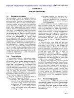
5. PROCEDURE AND SEQUENCE
General Plan
Due to the large dimension of foundation, detail of reinforcement, different of Bottom of
foundation contractor shall divide foundation into 07 stage to ensure safety condition and
quality of concrete (massive concrete): Vertical construction joint will be arranged between
Stage [3], Stage [5], Stage [6], Stage [7]; Isolation joint surround Stage [1], Stage [2], Stage [4].
Method statement for Fan will be separate and submit later
- 6 - | Page
Re v. A
VAN PHONG 1 BOT THERMAL POWER PLANT PROJECT
Stage "2.4" should be written down.
Why Pulverizers concrete
is divided into 2 and 3 ?
2.3
2.2
2.4
Stage "2.5" should be written down.
2.1
2.5
2.6
2.7
The stage from 2 to 7 will be carried out to follow the schedule of Anchor Bolts installation,
Contractor will arrange enough manpower and equipment to conduct these stages.
Besides, the calculation of concrete supply has to prepare to make sure the eligible
condition for cast concrete.
Between each stage, the Hy-rib permanent formwork will be used to avoid crack and so
forth between construction joints.
The expression of Stages is different from
Uni 1. Why ?
- 7 - | Page
Re v. A
VAN PHONG 1 BOT THERMAL POWER PLANT PROJECT
Construction Stage 1: SCC, Oil sump: 04 Phase
- 8 - | Page
Re v. A
VAN PHONG 1 BOT THERMAL POWER PLANT PROJECT
Construction Stage 2, 3, 4, 5, 6: Massive concrete, Maximum thickness: 3m
Where is Stage 7?
• Vertical construction joint will be arranged between Stage [3], Stage [4], Stage [5], Stage [6] And
Massive concrete will be describing in section 6.6 Concrete work.
Stage 4 is three Pulverizers ?
This is isolated joint ?
6. CONSTRUCTION WORK
6.1 Excavation and disposal
• The ratio 1:0.5 shall be applied for the slope of foundation, Typical section for excavation is shown in
picture below. Dimension of pit lager than dimension of foundation 2m for all direction for Scaffolding,
formwork.
This sentence cannot be understood.
This figure is wondering.
Why is dewatering pipe in the concrete of SCC
sump foundation ?
Typical of dewatering for SCC sump
In case of heavy rain, Contractor will use some water pumps to dewater; in addition, making
- 9 - | Page
Re v. A
VAN PHONG 1 BOT THERMAL POWER PLANT PROJECT
trenchs to collect water need to carry out. The layout of trench will be depended on the actual
condition on site, particularly, avoid obstructing other activities and easily collect water.
6.2 Lean concrete
• Subgrade of foundation must be well compacted unless surface is rock and cleaned up to ensure
the quality of lean concrete. Any marshy ground position must be removed and compacted by good
material. Lean concrete plan will depend on the construction step.
• Lean concrete thickness 50mm (as design drawing), grade: 15Mpa.
• Lean concrete is casted before next activities such as rebar or formwork installation.
6.3 Reinforcement work
• Steel bars shall be stored on the site on racks or supports of sufficient height to keep the bars clear
of the ground and steel bar shall be covered by plastic sheet in order to prevent corrosion by the
sea environment.
• Bar bending schedule shall be submitted before commencement of work.
• Fabricating, installing foundation rebar comply with the approved design, project specification, ACI
117 and ACI 318, approved BBS. Lap splicing method shall be used for rebar connection, the lap
length shall comply with the approved design drawing and applied standard.
• Any kind of hot cutting and bending rebar shall not be allowed
• Fabricated rebar will be transported from the workshop to construction site by lorry crane.
• Rebar shall be erected such as to form a rigid cage within the formwork, with every intersection
being bound together with appropriate binding wire.
• Specified concrete cover shall be maintained by the use of precast concrete spacer blocks of the
same grade as the concrete in which they are to be used.
- 10 - | P a g e
Re v. A
VAN PHONG 1 BOT THERMAL POWER PLANT PROJECT
• Black annealed steel binding wire of 1mm thickness shall be used for fixing the reinforcing bars.
The binding wire will be double folded to ensure the firmness of the connection.
• Concrete spacer shall be made by same grade concrete as structural grade.
• In practicable, the subcontractor could use extra method such as steel tube frame, cables,
turnbuckles… to keep the rebar stable before carry out the next steps
• Inspection of rebar installation shall be conformed to design drawing and approved method
statement, such as grid space, lap length, elevation…
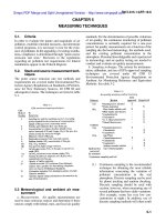
Support bars/rebar chairs are installed to make sure the enough safety and stable for rebar
frame against dead load of top rebars and live load of workers, equipment and casting concrete.
- 11 - | P a g e
Re v. A
VAN PHONG 1 BOT THERMAL POWER PLANT PROJECT
HANDRAIL
WORKING PLATFORM
DETAIL A
DETAIL A
TOP LAYER BAR
TUBE Ø48
1500
600
SUPPORT BAR
3000
SUPPORT BAR
600
600 3000 600
SIDE BAR
LEAN CONCRETE
250
1
0.5
BOTTOM LAYER BAR
SECTION
- 12 - | P a g e
Re v. A
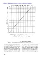
VAN PHONG 1 BOT THERMAL POWER PLANT PROJECT
8
7
6
5
3
400
2
400
4
1
The order of casting concrete will be followed from 1 to 8
6.4 Installation of embedded plate, box out (if any)
• The embedded plate/box out shall be erected in the exact position as specified in the designed
drawings.
• The characteristics of embedded items (supplied by Contractor) must confirm to specification,
approved design drawing such as type, size, and be approved before using
• Fixing method is suggested by wire tie and/or welding to fix stable anchoring frames. Welding to
main rebar is prohibited
• Typical method for installation is shown in figure below. (Method statement of Bolts installation will
be submitted by another contractor. Contractor will coordinate to IHI for this matter on site)
• Contractor must ensure the clean condition of embedded items, stability and firmness, position and
elevation, plumpness… before pouring concrete
Method for fixing anchor frames of Steel structure is
very important. Please show it on this MS.
- 13 - | P a g e
Re v. A
VAN PHONG 1 BOT THERMAL POWER PLANT PROJECT
6.5 Formwork
• Formwork kind shall be considered as mass concrete curing method
• Forms shall conform to the shapes, lines and dimensions of the structure according to the drawings.
• The formwork shall ensure good finished surface of concrete, and shall be sufficiently firmly and
tight for the method of placing and compacting and for preventing loss of grout from the concrete.
• Prior to reuse formwork, all dust and mortar, debris on the surface shall be removed.
• Working platforms for inspection and erection shall be provided.
• Contractor is using total station leveling machine to remark the reference point which the formwork
is fixed. Check elevation of rebar grid and add the concrete spacer where necessary and make
alignment to proper elevation specified of FC drawings
• Install the concrete spacer to ensure the protection cover thickness are achieved, Concrete spacer
shall be made by same grade concrete as structural grade.
• Connecting the formwork panel by connection pins and clips. Checking elevation, position, and
plumpness of panels. Using the support pipes, steel-box, scaffold clips to fix the formwork
• Formwork must ensure close to prevent leakage of cement laitance at inspection time.
• Space of pipe support, tie rod is 800mm.
• In height of foundation h=3m, arrange 3 layers for Pipe support, 5 layers of tie rod.
• In height of foundation h=1.5m, arrange 2 layers for Pipe support, 3 layers of tie rod.
- 14 - | P a g e
Re v. A
VAN PHONG 1 BOT THERMAL POWER PLANT PROJECT
Typical formwork panel
- 15 - | P a g e
Re v. A
VAN PHONG 1 BOT THERMAL POWER PLANT PROJECT
Typical detail of formwork for Boiler foundation
BOTTOM LAYER BAR
DETAIL 1
The support bars must be bent and fixed with bottom layer bar
- 16 - | P a g e
Re v. A
VAN PHONG 1 BOT THERMAL POWER PLANT PROJECT
6.6 Concrete work
• Reference Method statement: “VP1-0-L4-C-GEN-10007_ Method statement for General concrete
work” for requirement and describe of concrete work.
• This method statement mention for construction joint, massive concrete.
6.6.1
Construction Joint.
• Horizontal Construction joint: The concrete surface shall be roughened by air-water jet, after it has
reached its final set but not more than 12 hours after its placing was completed, so as to expose
the aggregate. In the case of more than 12 hours, use a handheld device to chipping. When fresh
concrete is to be placed on set concrete, a layer of mortar (water and cement only) shall be applied
by spray/brush on the dry surface before the fresh concrete is placed.
The mortar shall contain
the same proportions of cement as the concrete mix.
• Vertical construction joint shall be place as picture below:
• Metal mesh will be installed, replace the formwork at construction joint. Support system for
formwork in construction joint same in other side. if conduit, angle steel, etc... going through
construction joint, metal mesh shall be made shape follow it.
- 17 - | P a g e
Re v. A
VAN PHONG 1 BOT THERMAL POWER PLANT PROJECT
• When pouring new concrete stage, do not dismantle metal mesh, it will lay inside of concrete
permanent. a layer of mortar (water and cement only) shall be applied by spray/brush on the dry
surface before the fresh concrete is placed.
The mortar shall contain the same proportions of
cement as the concrete mix.
• At top of rebar layer, Contractor will use formwork to make the construction joint, when casting
concrete next time, Contractor will chip the concrete to make rough surface.
•
- 18 - | P a g e
Re v. A
6.6.2
Massive concrete.
VAN PHONG 1 BOT THERMAL POWER
PLANT
Method
ofPROJECT
managing temperature of fresh concrete less than
30degree, usage of chilled water, cover on aggregate and so
on should be stated refer to TG foundation.
Method of pouring Massive concrete (2700~3000m3) should
be stated, number of concrete pumps, concrete mixing trucks
and so on should be stated.
a) Pouring concrete
Mass concrete center temperature shall not exceed 70℃ and must be less than 50℃ per meter
Difference of temperature in center and surface of the concrete not exceed 20℃. The method of
curing the concrete will be complied with item b (see below).
Contractor will send a technical service team to provide peak temperature and
differential temperature monitor during the foundation casting and construction process so
that timely technical data could be provided to control and minimize the risk of thermal
cracks.
The following guidelines shall be followed;
• Concrete slump shall conform to approved mix design
• Concrete temperature at pouring time shall not exceed 30°C
• Sampling from trucks shall be advised by the Engineer/As per Site Inspection and Test Plan.
• Concrete shall be placed in position using the pump and flexible hose shall be connected at the
end of the concrete pump by clamping. Such hose shall be placed inside the pouring area to control
the height of pouring the concrete, Contractor will make plan for location of hose through top rebar
layer. Concrete shall be placed 400mm horizontal layers till reaching the required height bottom.
• Concrete should be discharged smoothly in coordination between vibrating person and
discharging person. Side vibration on formwork will be used if necessary.
• Concrete should not be dumped in several locations at a time nor discharged in large hips and
moved horizontally until final position.
• The concrete casting shall be performed layer by layer, preventing the formation of cold joints. The
layers shall be separated with heights not greater than 2/3 of the vibrator length.
- 19 - | P a g e
Re v. A
VAN PHONG 1 BOT THERMAL POWER PLANT PROJECT
• During placement of concrete and compaction, care would be taken to retain formwork position
from displacement and deflection.
• The calculation of concrete supply, transportation will be attached as attachment 3.
b) Curing and Temperature control
• Water shall be continuously introduced on the saturated burlaps in order to keep the burlaps being
wet at all time during curing period
• As soon as the concrete has reached the stiffening time approximately 1 hour after pouring a set
of burlap or plastic sheet shall be used to cover the whole concrete surface. Water shall be
continuously introduced on the saturated burlaps in order to keep the burlaps being wet at all time
during curing period.
• The measurement purposes are to finding the temperature development within the concrete mass.
The results will show peak temperature and the temperature differential for such measuring points.
• Thermocouple is a sensor. It will be installed inside of concrete and use for checking temperature
inside of casted concrete. The monitoring is progressed every 2 hours at each day and night.
- 20 - | P a g e
Re v. A
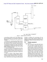
VAN PHONG 1 BOT THERMAL POWER PLANT PROJECT
2
1
1'
6
4
5
6'
7
8
7'
9
11
10
10'
12
• Sets of thermocouple will be installed and embedded inside concrete structure at full plan and
section. Top and bottom sets will be approximately 300mm of measuring from the edges. The heat
generated will be converted to the circuit and sent to the digital thermometer which will record and
show information of the temperature measure. Some thermocouples will be installed in a distance
of 1m to monitor the difference of temperature in 1m.
• The process of monitoring of temperature will follow this depiction:
+Immediately after the completion of casting, the Automatic Recorder will start to measure
temperature every 2 hours during the first 2 days (48 hours) and subsequently every 6 hours
up to 120 hours. After 120 hours, the measurement interval will increase to time per day
until the peak temperature falls down to 45oC and the difference temperature below 20oC
and the gradient to be controlled.
Why do not arrange for the Pulveriser foundation?
- 21 - | P a g e
Re v. A
VAN PHONG 1 BOT THERMAL POWER PLANT PROJECT
Table to record temperature inside mass concrete
+The formwork and insulation must only be removed after the peak temperature falls below
45oC and maintaining the difference temperature below 20oC and the gradient to be
controlled..
+Check peak temperature of each point (Tmax), especially the mid-point of the
foundation, maximum temperature at all time in the concrete shall be less than ≤ 70oC.
+Check the temperature difference ΔT1 and gradient ΔT/m between any 2 points of the
structure shall be less than 20oC (ΔT1≤ 20oC) and 50oC/m (ΔT/m≤ 50oC).
+Check the differential temperature ΔT of each measuring point.
+The temperature measures to be analyzed and reported daily.
• In the case, Difference of temperature in center and surface of the concrete exceed 20℃. Immediate
- 22 - | P a g e
Re v. A
VAN PHONG 1 BOT THERMAL POWER PLANT PROJECT
apply method statement: Cover top of surface by foam thickness 3cm, keep the side formwork until
the temperature differential between the middle of concrete mass and any outer surface is under
controlled. Water cured shall be continued for at least 7 days after pouring concrete.
• Side formwork shall be removed after 3-4 days after pouring concrete or when Difference of
temperature in center and surface of the concrete not exceed 20℃. Plastic sheet or burlap must be
still kept completely covering the exposed concrete surfaces and in a continuous moist condition
for the required curing period 7 days.
This method might not work
out for control the
differential temp and the
core temp <=70 deg cel.
Using pre-installed cooling
pipes is recommended.
c) Action plan for rain happened during casting
Check the weather forecast during the week when casting concrete
Plastic sheet will standby near concreting area, Contractor will cover by plastic to ensure
continue construction.
d) Other works such as backfilling work…
How is Plastic sheet set for continue
pouring concrete ? Please show the
method on figure.
The filling shall commence only after approval by Engineer-in-charge is obtained and after the
structures or pipes getting buried are approved.
- 23 - | P a g e
Re v. A
VAN PHONG 1 BOT THERMAL POWER PLANT PROJECT
Filling area surface shall be kept free from water, such as materials and debris.
Backfill material shall be selected material to the acceptance of the Engineer. It shall be free of
roots, stone or debris and checked for big stones or any other objects which may have on the
trench after installation piping.
Care must be exercised to protect, pipes, joints and other features from damage due to backfilling
and consolidation.
Fill materials shall generally be placed in layers, and uniformly compacted to the satisfaction of
the Engineer by field density test before the next layer is applied. Loose thickness of each layer
shall not be greater than 300mm.
Field density test (FDT), Material backfill shall be carried out according with ITP General Excavation
and Backfilling work.
Coating work… will be submitted by other submissions to get approval.
7. INSPECTION AND TESTING
Reference Method statement: “VP1-0-L4-C-GEN-10007_ Rev C_ Method statement for General
concrete work” for requirement and describe
8. ENVIRONMENT, HEALTH AND SAFETY (EHS)
Reference Method statement: “VP1-0-L4-C-GEN-10007_ Rev C_ Method statement for General
concrete work” for requirement, describe and Risk Assessment.
- 24 - | P a g e
Re v. A
VAN PHONG 1 BOT THERMAL POWER PLANT PROJECT
8.1 Risk assessment
Job / Task
People
Cause of
at Risk
Adverse Effect
Adverse Effect
L1
S1
RF
N
**
Control Measures
L2
S2
R
R
N
*
Assessment
4
Control measures will be
regularly reviewed and
monitored to assess their
suitability and
improvements made if
required.
If any change is made to
the working condition or
operation i.e. change in
sequencing, new
plant/equipment or new
workers involved, a new
risk assessment will be
conducted and further
control measures
implemented to suit the
operation.
I- PREPARATION ACTIVITIES - Manpower & Equipment & Material & Site Preparation
Mobil. of
Manpower
Site
personnel
/Public
/Other
Subcontracto
rs
[ Safety ]
- Incompetent
personnel for
job
- Untrained and
unstill
- Unauthorized
vehicles and
pedestrians
passing through
site entrances
- Lack of
suitable
access/egress
from the
project
location
- Lack of
awareness and
suitable control
measures
implemented
[ Safety ]
- Personnel
injury
- Traffic
accident
- Social crimes
- Serious
personnel injury
- Theft
3
3
9
[ Safety ]
- Competent persons must be choose with
suitable and talent, skill for job. Their full
legally documents with certificates, license
must be checked and submitted for basic
induction and recording. Full PPE required
- Gate Entry: only authorized persons to
enter site with the relevant ID card and
site pass for vehicle. Each person use their
own ID card. Borrow, lending, use other
ID for entry is not allow and be fired off
from the site if caught
* Both documents shall be given to
personnel who have
undertaken an EHS induction training.
- Movement only at suitable
access/egress locations, signage,
pedestrian walkways and routes as per
guiding or direction signboard shown.
Designated way will be followed of the
site traffic management plan and site
layout plans
- Obeying of speed limits which be
enforced for jobsite and public road.
- Following and caution to warning
signage which be erected on all routes.
- 25 - | P a g e
Re v. A
2
2