Vp1 ms for pre boring phc pile
Bạn đang xem bản rút gọn của tài liệu. Xem và tải ngay bản đầy đủ của tài liệu tại đây (1.72 MB, 35 trang )
For Approval
VAN PHONG 1 BOT THERMAL POWER PLANT PROJECT
WORK ITEM: TEST PILE WORK
REV
DATE
DESCRIPTION
Doc Title: Method Statement for T
Approved
Checked
Prepared
OWNER
VAN PHONG POWER COMPANY LIMITED
PROJECT
Van Phong 1 BOT Thermal Power Plant Project
Status
□Approved
□Approved with Comment
□Not Approved
□Reviewed
OWNER’S ENGINEER
Pöyry Switzerland Ltd.
EPC CONTRACTORS
IHI–TESSC–CTCI–DHI CONSORTIUM
PROJECT DOCUMENT No
VP1-
REV
DOCUMENT TITLE
METHOD STATEMENT FOR TEST PILLING WORK
EPC
EPC DOCUMENT No.
REV
VAN PHONG 1 BOT THERMAL POWER PLANT PROJECT
WORK ITEM: TEST PILE WORK
Doosan Heavy Industries and Construction
Doc Title: Method Statement for Test pile works
VP1-
VAN PHONG 1 BOT THERMAL POWER PLANT PROJECT
WORK ITEM: TEST PILE WORK
Doc Title: Method Statement for Test pile works
CONTENTS
1. PREFACE................................................................................................................2/29
2. REFERENCES .......................................................................................................2/29
3. SCHEDULE……………………………………………………………….......…….3/29
4. SITE ORGANIZATION……………………..……………..………………………3/29
5. MOBILIZATION PLAN OF WORKFORCE.....................................................3/29
6. MOBILIZATION PLAN OF CONSTRUCTION HEAVY EQUIPMENT.......4/29
7. MATERIAL.............................................................................................................4/29
8. CONSTRUCTION METHOD...............................................................................6/29
9. STATIC LOAD TEST............................................................................................9/29
10. TENSILE LOAD TEST .......................................................................................14/29
11. HORIZONTAL STATIC COMPRESSION TEST ..........................................18/29
12. HIGH STRAIN DYNAMIC LOAD TEST ........................................................22/29
13. QUALITY CONTROL ........................................................................................25/29
14. ENVIRONMENT, HEALTH AND SAFETY ...................................................25/29
1. PURPOSE OF TEST PILE:
-
Determine the characteristic value of the pile and provide test parameters for
engineer pile foundation.
VAN PHONG 1 BOT THERMAL POWER PLANT PROJECT
WORK ITEM: TEST PILE WORK
Doc Title: Method Statement for Test pile works
a. The load (compressive and lateral) test measures the vertical and lateral
deformation of the deep foundation.
b. The tension (uplift) load test is performed to determine axial tensile (uplift)
load capacibilities of piles.
c. The Dynamic load testing is used to provide data on strain, force,
acceleration, velocity, and displacement of a pile under an axially applied
impact force.
Pile Diameter
D800 – Class
B
D600 – Class
A
D600 – Class
A
Quantity of
test pile
3
Location
Kind of testing pile
Chimmey
Vertical,, Lateral and Uplift load test
3
Coal Storage
Vertical,, Lateral and Uplift load test
3
Water
Treatment
Vertical,, Lateral and Uplift load test
2. Scope of work:
The scope of tesing piling work is the static load test and dynamic load test
will be conducted for one PHC D800 type B pile and two PHC D600 Type A.
Detail location is shown on the Attachment #1, PRELIMINERY TEST PILE PLAN
PLOT PLAN_VP1-0-L4-C-GEN-00021.
The pile PHC D600 – Type A and D800 – Type B for production pile is shown
on the Attachment #2, PHC-D800-01-VP1 and PHC-D600-02-VP1.
3. PREFACE
DOOSAN heavy industries & construction (DHI), the EPC Contractor of project,
herewith submits this method statement to describe the methodology regarding
implementation plan for the test piling works.
DHI intends safe, reliable and quality execution of its scope to the maximum extent
that can be achieved.
3.1DEFINITION
Project
Project
Company/Owner
Contractor / DHI
Subcontractor
Van Phong 1 BOT Thermal Power Plant
Doosan Heavy Industries & Construction
Phan Vu Investment Corporation
1.2 Application
Application of this Method Statement is limited to the scope of test piling of
Pre-drilled PHC piling works.
VAN PHONG 1 BOT THERMAL POWER PLANT PROJECT
WORK ITEM: TEST PILE WORK
Doc Title: Method Statement for Test pile works
4. REFERENCE
a. Construction Drawings (includes all reference drawings, schedules,
sketches, etc)
b. DOOSAN/Owner Project Specifications
c. JIS A5373-2010 “Pre-stressed Spun Concrete Piles (PHC pile)”
d. TCVN 7888-2014 Pre-tensioned spun concrete pile.
e. TCVN 10667-2014 Spun concrete pile – Pile drilling and Installing –
Construction and acceptance.
f.
TCVN 9393-2012 Piles – Standard test method in situ for piles under axial
compressive load.
g. TCVN 9394 : 2012 Pile Pressing and Driving – Standard for construction,
checking and acceptance
h. ASTM D 1143 - “Standard test method for Deep Foundations under Static
Axial Compression Load”
i.
ASTM D 3689 - “Standard test method for Deep Foundations under Static
Axial Tensile Load”
j.
ASTM D 3699 - “Standard test method for Deep Foundations under Lateral
Load”
k. ASTM D 4945 - “Standard Test Method for Pile under PDA/DLT”
5. Schedule
VAN PHONG 1 BOT THERMAL POWER PLANT PROJECT
WORK ITEM: TEST PILE WORK
Doc Title: Method Statement for Test pile works
6. Site organization
7. MOBILIZATION PLAN OF WORK FORCE
Assigned Position
Number
Foreman
Crane driver
Drilling and drive machine driver
Welders
Mixing Machine operator
Surveyors
General labors
1
1
1
2
1
1
2
Remarks
Mixer and Pump, etc.
VAN PHONG 1 BOT THERMAL POWER PLANT PROJECT
WORK ITEM: TEST PILE WORK
Doc Title: Method Statement for Test pile works
8. MOBILIZATION PLAN OF CONSTRUCTION HEAVY EQUIPMENT
Heavy Equipment
Crawler Crane
Upper auger
Under auger
DH608-120M(Base machine)
Mixing machine
Excavator
Compressor
Air hammer
Electric Generator
Generator for Base machine
Number
1
1
1
1
1
1
1
1
1
1
Capacity
Remarks
150T
9T
14T
65T
7T
15T
9T
3T
3.7T
3.7T
Consist of Mixer and Pump,.etc
.
If needed
9. MOBILIZATION PLAN OF TESTING EQUIPMENT
Testing Equipment
Number
Certificate
No.
Remarks
VAN PHONG 1 BOT THERMAL POWER PLANT PROJECT
WORK ITEM: TEST PILE WORK
Doc Title: Method Statement for Test pile works
10.MATERIAL
10.1
Hardening Cement Milk Grouting
Mixing & Strength Test
-
Compressive strength test should be carried out at laboratory & site
(R28>=20Mpa)
During mixing, the concrete temperature should be managed constantly.
Mix design and raw material for pile D600A, pile length 20m and Drilling
holes diameter D700.
-
-
10.2
Cement
2400 kg
Water
1700 L
Compressive Strength
200 kg/cm2
Mix design and raw material for pile D800B, pile length 20m and Drilling
holes diameter D900.
Cement
3,330 kg
Water
2,330 L
Compressive Strength
200 kg/cm2
PHC Pile
Piles shall be manufactured in accordance with JIS A 5373
(or equivalent Vietnamese code)
No
.
Diameter
(mm)
Clas
s
Effective Prestress
(N/mm2)
Thickness
(mm)
Compressive
Strength of
Concrete
(N/mm2)
Allowable
Axial Force
(tonf)
1
600
A
4.0
90
80
155
2
800
B
8.0
110
80
300
11.CONSTRUCTION METHOD
11.1
Description
Using Auger Drill Machine, a pre-drilled hole is obtained where hardening cement
slurry is filled to harden the root soil at the pile tip. PHC(Pre-tensioned High
strength Concrete) precast piles that are manufactured at the shop are to be
inserted inside the hole. Pile fixing slurry is filled into the gap in order to
enhance friction force between pile and the surrounding soils. Several light
blows on the pile head should be subsequently conducted in order to secure the
VAN PHONG 1 BOT THERMAL POWER PLANT PROJECT
WORK ITEM: TEST PILE WORK
Doc Title: Method Statement for Test pile works
bearing layer at the pile tip elevation.
11.2
Working Procedure
a. Drill to the design depth with spiral auger, the diameter of borehole shall be
larger than PHC pile diameter 10cm.
The slime at the bottom of bore hole could not be treated after completion of
drilling.
b. Pull up earth auger, remove some soil cutting, injecting root–hardening cement
slurry through hollow drilling rod with proper pressure after drilling to
predetermined depth.
c. Pull out the earth auger completely, inserting the PHC pile into borehole with its
own weight.
d. PHC pile is fixed to the bearing capacity by hammer (The capacity of PHC pile is
6281kN) (For multi-segment pile, splicing will be applied at a service hole before
installing pile).
e. A pile is fixed to bearing layers by the drop hammer.
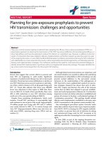
Light Blow
BlowBento
nite
Hardeni
ng
cement
4. Completion of Predrilled hole
1. Auger
Drilling
f.
2. Slurry
3. Auger pulling up
Injection
5. Pile Insertion
6. Light Blow
Auger could not be in the slurry during injection of grout. The auger will
withdraw when pump slurry into hole.
11.3
Excavating soil with air compressor
a. Excavating soil from the ground to designed depth by drilling with air compressor.
b. During construction, the excavating soil shall be collected by excavator.
VAN PHONG 1 BOT THERMAL POWER PLANT PROJECT
WORK ITEM: TEST PILE WORK
Doc Title: Method Statement for Test pile works
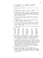
(Excavating Soil to Designed Depth
By DTH Method’s Auger Machine)
c.
Borehole will be kept as vertical during drilling. .
11.4
Cement Milk Grouting
Before and after pile-inserting into the hole, hardening cement milk grouting shall
be filled respectively. After excavation reach to the designed depth, the cement
milk grouting shall be injected into the borehole. Cement milk grouting will be
mixed at mixing machine based on approved mix design. Root milk grouting goes
through drilling rod to bottom of drilled hole with designed volume. Fixed milk
grouting to be pumped from top of borehole after inserting pile will be filled in the
gap beween pile and wall of hole due to cement will be deposited after one day.
Cement milk grouting take a role in strengthening bearing capacity at pile tip and
recovering & rebonding side friction of pile.
Cement milk grouting should be complied with requirement of JRA code. The time
for slurry to get hard is approximately 2 ÷ 4 hours (According to machenical
target of Cement PCB40 of Nghi Son using at site).
11.5
Installing pile
a. After the filling up cement milk grouting is completed, the PHC pile shall be installed
immediately into the borehole to the designed depth.
b. Pile shall be settled slowly by service crane
c. Two perpendicular vertical directions will be controlled by mean of plumb-line and
theodolites to adjust position and direction of piles. The verticalty of pile shall be
observed by the theodolites
d. Before installing the pile, the ground shall be made evenly. The flat working ground
shall minimize the displacement of pile.
VAN PHONG 1 BOT THERMAL POWER PLANT PROJECT
WORK ITEM: TEST PILE WORK
Doc Title: Method Statement for Test pile works
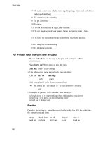
(Installing pile by crane and pile is fixed to the bearing capacity layer by light
hammering)
e. After installing pile, the Cement Milk will over flow on the ground, at that time the
Cement Milk will flow to the gutter had been excavated.
f.
When Cement Milk over flow on the ground, Ground water inside the borehole will be
pushed out with gravitation of Cement Milk due to graviation of Cement Milk heavier
than ground water.
g. Using light blow driving pile head until fix to the ground and then using two direct
which have been located at the near distance to check vertical of pile head.
h. Vertical tolerance of pile will be applied in TCVN 10667 at page 18 item 9.2.8
indicated the vetical tolerance is 1% of pile length are accepted.
11.6
Pile connection
In case the pile jointing is necessary, welding connection type can be adopted.
Splicing pile segments shall be done by welding connection. The bottom and the
upper pile segment shall be spliced at the service hole.
The welding joint shall be filling-up all around the gap between the two piles-end
flanges by 3 layers welding. All welding joints shall be carried out by skilled worker,
who has welding certificate, under carefully supervise about thickness, quality as
well as the verticality of two pile segments before and after welding. Semi automatic welding equipment with welding wire shall be used for welding joint of
pile.
borehole)
(Inserting pile into borehole by crane) (Splicing the top pile segment at the
-
WPS for Welding joint will be applied as content below
Quy trình hàn và kiểm soát chất lượng mối hàn
Procedure for welding and checking welding quality
1. Quy trình hàn/ welding procedure:
Bước 1/step 1:
VAN PHONG 1 BOT THERMAL POWER PLANT PROJECT
WORK ITEM: TEST PILE WORK
Doc Title: Method Statement for Test pile works
.
11.7
-
Welder certificate will be supplied to QC and EHS team.
-
MT test will be applied to ITP.
-
The bottom pile will be fixed by wood and checked by level rular when
welding joint with the upper pile.
Light blow
In order to ensure that the inserted pile is set on the required elevation (drilled tip
elevation), the light blows using ram should be conducted.
The Light blow will be used to fix the pile get the required elevation with the weight
from 2.5T – 3.7T.
11.8
Illustrations for the working activities
VAN PHONG 1 BOT THERMAL POWER PLANT PROJECT
WORK ITEM: TEST PILE WORK
Doc Title: Method Statement for Test pile works
(Installing Base machine, Upper Auger, Lower Auger)
(Installing pile into borehole)
(Pulling out casing after installing pile)
Just using casing in case the soil was been colapsed.
12.STATIC LOADING TEST
12.1
Introduction
a. Static loading test provides the relationship between loads - settlement of the pile
to determine the axis bearing capacity of the pile working in the land. Piles are
tested by the method loading each level up to maximum loading.
b. Testing standard application : ASTM D 1143 - “Standard test method for Deep
Foundations under Static Axial Compression Load”.
c. Static loading test is conducted in accordance with the standard testing
regulations. Loading on the head pile is made by a specialized hydraulic system
through a hydraulic pump and controlled by the pressure meter for the whole
system.
d. Pile settlement is monitored by meter system setting at four positions on the
head pile, matching symmetric through the pile center. The meters are mounted
on the stand independent to testing pile.
VAN PHONG 1 BOT THERMAL POWER PLANT PROJECT
WORK ITEM: TEST PILE WORK
12.2
Doc Title: Method Statement for Test pile works
Testing Equipment
Before setting of counterweight, the area of loading will be wellcompacted to avoid of overload on the ground surface or incident during
test.
Equipment for a set of experiments, including:
a. Counterforce system
Bearing, steel floor and a slab of concrete (concrete blocks) are included.
Floor system includes 01 main beam with high intensity steel. The main beam
is built in factories and the steel welding high strength.
Beams are arranged to transmit loading capacity to center hydraulic system
through the thick steel pad. The beam is strengthened forming a solid floor.
The sub-beams are placed directly and perpendicularly to the main beam. The
head sub-beams are also put on the concrete in order to ensure stability and
safety during testing procedure.
Counterweight above using precast concrete blocks specializes for static
loading test.
b. Loading part
Hydraulic jack synchronization system consist of the specialized hydraulic, the
total lifting capacity ensure larger than 150% largest testing load. Hydraulic
system is put on the head pile through the steel pad to ensure loading evenly
on the head pile. Center of Hydraulic system coincides with pile center.
All devices have to be on the certificate verification period effect.
c. Settlement monitoring device
Use 04 sensors type will be applied. The meters tighten to the standard beam
system. The meter has a certificate verification period effect.
Standard steel box beam system is attached to the brackets to independent
test pile. Gradienter will be used to check the stability of the standard beam
system through mold fixed set remote area experiments.
VAN PHONG 1 BOT THERMAL POWER PLANT PROJECT
WORK ITEM: TEST PILE WORK
12.3
Doc Title: Method Statement for Test pile works
Testing steps
a. Preparation works
- Collect full manuals is involved.
Pile construction documents, designing profile, geological geotechnical
survey
-
records. Receiving test piles and construction plan. Cleaning plan,
Consider the entire region including
underground works, works on high place, power, water.
Plan and implement formal measures in the organization has worked out
measures including drainage, internal roads, space for equipment, work
area
b. Process the head of the test piles
The pile was tested as the pile reached the design strength of the plan or age
of concrete. Part bleach to cut the pile of concrete features makes creating
plane surfaces. If the head of the test pile is not flat or crack and porous to
process flat again with glue epoxy mixed sand
c. Installing the hydraulically jacks
- Mark center of the test pile
- Install steel pad and proceed to check center pile upper pad
- Install the hydraulically jacks and adjust the jack system to make sure the
general load in central of the pile
d. Reinforced base, installation floor systems
- Survey site base, calculate intensity to determine the size of bearings
- Install main beams, check the monitor, invisible, and tension wires
- Reinforced the bearings if necessary. Installing packages, check with your
-
bearing and geodetic tension wire, placed on top of bearings support
beams
Installing additional beams, Installation from the center outward, the
beam sub-assembly is equal, all different ways
Counterweight installation : Installation of large concrete blocks before,
after the smaller blocks. For each class to load flat, square brief, alternate
VAN PHONG 1 BOT THERMAL POWER PLANT PROJECT
WORK ITEM: TEST PILE WORK
Doc Title: Method Statement for Test pile works
layers to avoid the same rate circuit, a key corner. Classes are also
classified for downloading from the center out and sequentially lower
grade to grade on
e. Install monitoring system
- Install 4 sensors, pressure meter, supporting main beam
- Test the sensitive of sensors, pressure meter before conduct testing
- stall geodetic machine: Create geotechnical mark on the main beam and
standard marks
- stall pump - system, hydraulic clock: Hydraulic hoses and switch, connect
pump and jack, test hydraulic jack before conduct testing
l.
12.4
a.
b.
c.
d.
e.
f.
g.
h.
i.
j.
12.5
Testing
- Trial load up to 5% design loading to check equipment
- Load to test (see the testing procedure tables below)
- Record the site data based on the testing procedure below
Testing report
Project name and location
The owner, designer, pilling contractor and the tester.
Test pile size, length, effective prestressed
Tested pile records
General testing results
Load-settlement relationship graphs
Settlement - time relationship graphs of each level load
Graphs of load and settlement to time
Calibration of testing equipment will be submitted.
Remarks.
Table of testing procedure
VAN PHONG 1 BOT THERMAL POWER PLANT PROJECT
WORK ITEM: TEST PILE WORK
12.6
Doc Title: Method Statement for Test pile works
Table of testing procedure
Load level (% design load)
5%
Before loading
Action to be taken after each load step
Leave for 10 minutes, checking equipments
Take the initial reading
25%
Leave until the rate of settlement is leveled to less than
0.25mm per hour but no longer 2hrs
50%
Ditto
75%
Ditto
100%
Ditto
125%
Ditto
150%
Ditto
175%
Ditto
200%
Leave until the rate of settlement is leveled to less than
0.25mm per hour or 12 hours
150%
Leave for 60 minutes
100%
Ditto
50%
Ditto
0%
Leave for 12hrs
Note:
-
For pile head displacement of less than 10mm, each load increment shall be
maintained until the rate of settlement is reducing and is <= 0.1mm/hour.
-
For pile head displacement of greater than 10mm, each load increment shall be
maintained until the rate of settlement is reducing and is <= 0.2mm/hour.
Loading time: Settlement recording at 0, 5, 10, 20, 40, 60, 80, 100, 120, 180, 240,
300, 360, 420, 480, 540, 600, 660, 720 minutes and after every 120 minutes
The testing will be ceased in case:
1. Completing testing procedure
2. Testing equipment is in trouble
3. Pile is “damaged” when one of the following phenomena:
- Pile material is damaged.
- Allowance settlement of each load value.
- The settlement of pile beyond the limit of 15% diameter piles
VAN PHONG 1 BOT THERMAL POWER PLANT PROJECT
WORK ITEM: TEST PILE WORK
Doc Title: Method Statement for Test pile works
- Pile suddenly settle, not keep the pressure as in procedure
All cases must be reported to the supervising engineer to carry out methods of
treatment or check before acceptance.
Submit test result.
13.TENSILE LOAD TEST
13.1
Introduction
Tensile load test provides the relationship between loads - displacement of the
pile to
determine the vertical uplifting capacity of the single pile.
Tensile load test is conducted in accordance with the standard testing
regulations.
Loading on the head pile is made by a specialized hydraulic system through a
hydraulic
pump and controlled by the pressure meter for the whole system.
Pile displacement is monitored by meter system at four positions on the head
pile,
matching symmetric through the pile center. The meters are mounted on the
stand
independent to testing pile.
13.2
Testing equipment
Equipment for a set including
VAN PHONG 1 BOT THERMAL POWER PLANT PROJECT
WORK ITEM: TEST PILE WORK
Doc Title: Method Statement for Test pile works
a. Counterforce system
Counterforce system is horizontal beams with high intensity steel and anchor
rod.
Bearing capacity of beams is greater than maximum testing load. Two beam’s
ends
are put on concrete blocks.
b. Loading part
Synchronization system consist of the specialized hydraulics, the total lifting
capacity ensure larger than 150% largest testing load. Hydraulic system is put
on the horizontal beams; above it is plate which fix to the head pile through
the anchorage bars. Bearing capacity of the anchorage bars is larger than the
maximum test load. Center of Hydraulic system coincides with pile center.
Pumping station is manufactured synchronization with Hydraulic system.
Pressure meter type is 100MPa or equivalent.
c. Displacements monitoring
Use 04 sensors with the degree of accuracy is 0.01mm. The meters tighten to
the standard beam system. The meter is placed in the head pile and
symmetric to
center pile. The meter has an effective verification period certificate.
Standard steel box beam system is attached to the brackets to independent
test
VAN PHONG 1 BOT THERMAL POWER PLANT PROJECT
WORK ITEM: TEST PILE WORK
Doc Title: Method Statement for Test pile works
pile. The brackets are arranged so that distance from the test pile to the
bracket
not less than 1.5m.
13.3
Testing step
a. Preparation works
Collect full manuals is involved: pile construction documents, designing
profile, geological geotechnical survey records
b. Installing the horizontal beam
Survey the site and testing area, calculations to determine the method of
anchorage.
Installing the horizontal beam, check by plumb line, bubble tube and tension
wire.
c. Installing the hydraulically jacks
- Install the hydraulically jacks and align.
- Installing the anchor plate, anchor rod, connection between the anchor
plate
and reinforcing bar of test pile is wedged method.
d. Installing monitoring system
- Install sensors, pressure meter, supporting main beam;
- Test the sensitive of sensors, pressure meter before conduct testing
- Install geodetic machine: Create geotechnical mark on the main beam and
standard marks
- Install pump - system, hydraulic clock: Hydraulic hoses and switch, connect
pump and jack, test hydraulic jack before conduct testing.
e. Testing
- Trial load up to 5% design loading to check equipment
- Load to test
- Record the site data based on the testing procedure below.
f. Testing report:
In accordance with ASTM D3689, the result shall include each tensile load
test.
g. Testing procedure: