Báo cáo hóa học: " Efficient Performance of Electrostatic SprayDeposited TiO2 Blocking Layers in Dye-Sensitized Solar Cells after Swift Heavy Ion Beam Irradiation" pdf
Bạn đang xem bản rút gọn của tài liệu. Xem và tải ngay bản đầy đủ của tài liệu tại đây (529.94 KB, 7 trang )
NANO EXPRESS Open Access
Efficient Performance of Electrostatic Spray-
Deposited TiO
2
Blocking Layers in Dye-Sensitized
Solar Cells after Swift Heavy Ion Beam Irradiation
P Sudhagar
1
, K Asokan
2
, June Hyuk Jung
1
, Yong-Gun Lee
3
, Suil Park
1
, Yong Soo Kang
1*
Abstract
A compact TiO
2
layer (~1.1 μm) prepared by electrostatic spray deposition (ESD) and swift heavy ion beam (SHI)
irradiation using oxygen ions onto a fluorinated tin oxide (FTO) conducting substrate showed enhancement of
photovoltaic performance in dye-sensitized solar cells (DSSCs). The short circuit current density (J
sc
= 12.2 mA cm
-2
)
of DSSCs was found to increase significantly when an ESD technique was applied for fabrication of the TiO
2
blocking layer, compared to a conventional spin-coate d layer (J
sc
= 8.9 mA cm
-2
). When SHI irradiation of oxygen
ions of fluence 1 × 10
13
ions/cm
2
was carried out on the ESD TiO
2
, it was found that the energy conversion
efficiency improved mainly due to the increase in open circuit voltage of DSSCs. This increased energy conversion
efficiency seems to be associated with improved electronic energy transfer by increasing the densification of the
blocking layer and improving the adhesion between the blocking layer and the FTO substrate. The adhesion
results from instantaneous local melting of the TiO
2
particles. An increase in the electron transport from the
blocking layer may also retard the electron recombination process due to the oxidized species present in the
electrolyte. These findings from novel treatments using ESD and SHI irradiation techniques may provide a new tool
to improve the photovoltaic performance of DSSCs.
Introduction
Dye-sensitized solar cells (DSSCs) are a promising
photovoltaic system f or next generation solar cells that
contain mesoporous nanocrystalline semiconductors like
TiO
2
, ZnO and SnO
2
as photoanodes anchored with dye
molecules. These dye molecules serve as light harvesters
[1-3]. It is believed that DSSCs are more cost effective
than conventional solar cells due to their low produc-
tion cost. Recently, intensive re search activities have
focused on enhancing the photoconversion efficiency of
DSSCs by improving charge transpo rt in the electronic
interfaces such as (a) TiO
2
/transparent conducting oxide
(b) TiO
2
/electrolyte (c) dye/TiO
2
(d) dye/electrolyte and
(e) electrolyte/counter electrode. For instance, electrons
on either side of the TiO
2
layer or in the transpa rent
conducting oxide (TCO) such as fluorinated tin oxide
(FTO) may recombine with the oxidized redox couples
such as I
3
-
. Electron recombination is one of the major
factors that determine the high energy conversion effi-
ciency (2e
-
+I
3
-
® 3I
-
) [4,5]. Therefore, there have been
several different approaches to reduce or block the
recombination of electrons on TCO and TiO
2
layers to
improve the energy conversion efficiency. Among the
interfaces described previously, the one between TiO
2
/
transparent conducting oxides faces severe recombina-
tion problems, since the porous nature of photoanodes
results in uncovered sites on the TCO layer, resulting in
sites for electron re combination with I
3
-
redox species
in the electrolyte.
Considerable attention has been focused on the meth-
ods to reduce electron recombination at the interface
between TCO substrate and electrolyte containing I
3
-
.
In order to overcome this recombination problem, a
compact oxide layer (pore-free and dense) is commonly
introduced between the mesoporous TiO
2
and the TCO
substrate, which blocks electron recombination with the
electrolyte via a so-ca lled blocking effect [6]. Further-
more, the blocking layer should provide good adhesive
properties between the TCO and the mesoporous TiO
2
* Correspondence:
1
Center for Next Generation Dye-Sensitized Solar Cells, WCU Program,
Department of Energy Engineering, Hanyang University, Seoul, 133-791,
South Korea.
Full list of author information is available at the end of the article
Sudhagar et al. Nanoscale Res Lett 2011, 6:30
/>© 2010 Sudhagar et al. This is an Open Access article di stributed under the terms of the Cre ative Commons Attribution Lic ense
( which permits unrestricted use, distribution, and reproduction in any medium, provided
the ori ginal wo rk is properly cited.
layers to facilitate electron transport from the mesopor-
ous TiO
2
to the TCO layers. From this perspective, a
variety of oxides have been inve sti gated such as Nb
2
O
5
[7], ZnO [8], MgO [9], Al
2
O
3
[10] and SiO
2
[11] in
addition to TiO
2
[12]. Different preparation techniques
have been widely exploited to form blocking layers such
as sol-gel [12], spin coating [13], sputt ering [14,15] and
spray-coating [16] techniques. Therefore, the formation
of a blocking layer between mesoporous TiO
2
and the
TCO substrate has been investigated, which no t only
blocks electron recombination but also facilitates elec-
tron transport.
In this study, electrostatic spray deposition (ESD) was
applied first for fabricating a TiO
2
blocking layer, and
swift heavy ion beam irradiation (SHI) was subsequently
performed as a post-treatment, since ESD allows particle
size and shape to be controlled by varying processing
parameters such as the polymer concentration in the
spray solution and applied voltage. Furthermore, a
conventional electrospinning setup, in which the con-
ducting FTO electrode directly connected to the electric
circuit (negative terminal) may produce an electro-
hydrodynamic field between a collector (FTO) and a sol
injector (syringe), may impro ve adhesion between the
sprayed particles and the FTO substrate. Particle growth
achieved via ESD is more effective than that obtained by
conventional spray pyroly sis [17] or spin coating. Chen
et al. [18] reported nanostructured TiO
2
films fabricated
by ESD and studied their phase transformations by sin-
tering. Zhang et al. [19] demonstrated the f easibility of
ESD-derived uniform TiO
2
particles in DSSCs and sug-
gested that the electrical contact between the con duct-
ing substrate and TiO
2
particle (electron transport layer)
plays a crucial role in power conversion efficiency, since
the presence and the removal of the polymer molecules
in the ESD layer during sintering may result in poor
contact among TiO
2
nanoparticles and poor adhesion to
conductive glass substrates. These will impose severe
constraints on the electron transport from the mesopor-
ous TiO
2
layertotheFTOsubstrate.Therefore,an
alternative post-treatment may be necessary to obtain a
compact, thin blocking layer with good contact among
TiO
2
nanoparticles and good adhesion to the conductive
glass substrates [20], resulting in rapid electron trans-
port. SHI was employed as a post-treatment for improv-
ing both adhesion and contact. R ecently, Singh et al.
[21] reported that SHI irradiation improved the trans-
mittance of conducting substrates (indium-doped tin
oxide), and their performance was affected in DSSCs.
The SHI method is based on the interactions of ions
with solids, where the temperature around the trajectory
of the ion increases remarkably. The shock waves,
or so-called pressure waves, develop due to the
temperature spike, which diffuses the heat radially in
the target [22]. This thermal spike can generate local
heat along TiO
2
nanoparticles. When the temperature is
greater than the melting temperature of TiO
2
(~1,300
°
C), a liq uid phase is fo rmed in this spec ific
region. This high tempe rature region cools down imme-
diately due to very rapid heat transfer to the surround-
ings, resulting in solidification of the surface, specifically
melted TiO
2
nanoparticles [23] that form a highly adhe-
sive TiO
2
blocking layer with the FTO substrate. To
best of our knowledge, this is the first report of its kind
to apply the SHI irradiation technique for obtaining an
efficient blocking laye r in D SSCs. The performance of
the SHI-irradiated blocking layer was investigated in
comparison with the unirradiated (pristine) and conven-
tional spin-coated TiO
2
blocking layers.
Experimental
The following procedure was used for the preparation of
a TiO
2
blocking layer on fluorinated tin oxide (FTO) sub-
strates: 15 wt% poly(vinyl acetate) (PVAc) (Mn ~
5,000,000) solution was prepared by dissolving PVAc in
dimethyl formamide (DMF) and dropping it into a mix-
ture containing 1 g of titanium isopropoxide and 0.5 g of
acetic acid while stirring. The as-prepared TiO
2
sol was
electrosprayed onto a grounded FTO substrate at 17 kV
with a constant distance of about 10 cm between FTO
and the electrospray syringe at a flow rate of 1.0 ml/h.
The resultant ESD TiO
2
blocking lay er was ~1.1 μm
thick and was sintered at 450°C for 30 min in air. In
order to prepare SHI-irradiated films, the as-prepared
ESD TiO
2
films were used without sintering.
SHI was conducted using 15 UD Pelletron tandem
accelerator facilities available in the Materials Science
Beamline at the Inter-University Accelerator Centre
(IUAC), New Delhi, India. The vacuum of the experi-
mental chamber was in the range of 10
-6
torr. The TiO
2
films, which act as blocking layers, were subjected to
100 MeV O ion i rradiation with fluence of 1 × 10
13
ions/cm
2
. The electronic and nuclear energy loss values
for 100 MeV O ions in TiO
2
, calculated using the SRIM
code simulation program (SRIM-2010) [24,25], were
1.284 × 10
2
and 6.739 × 1 0
-2
eV/Å, respectively. The
range of O ions in this experiment is about 54.14 μm,
indicating that the entire passage of ions in the film is
dominated by electronic energy loss. Further experimen-
tal details were published elsewhere [26].
In order to compare the effect of the blocking layer,
two kinds of DSSCs were assembled: (a) a pristine cell
fabricated from the ESD TiO
2
blocking layer an d (b) a
SHI cell using an irradiated ESD TiO
2
blocking layer. In
addition, a reference cell was fabricated from the TiO
2
blocking layer prepared by conventiona l spin coating (Ti
(IV) bis (ethyl acetonato)-diisopropoxide solution in
2 wt% of 1-butanol) and was also tested under identica l
Sudhagar et al. Nanoscale Res Lett 2011, 6:30
/>Page 2 of 7
experimental conditions. Further, TiO
2
photoanodes
thickness about ~6 μm were prepared on the TiO
2
blocking layer using TiO
2
paste (Solaronix) by a doctor
blade technique [27] and subsequently sintered at 450°C
for 30 min in air.
N719 dye (di-tetrabutylammonium cis-bis(isothiocya-
nato)bis(2,2’-bipyridyl-4,4’-dicarboxylato)ruthenium(II))
was used to sensitize the TiO
2
photo electrodes. The
TiO
2
electrodes were immersed overnight in a 0.3 mM
dye s olution containing a mixture of acetonitrile (ACN)
and t-butyl alcohol (1:1 v/v) and dried at room tempera-
ture. A sandwich-type configuration was employed to
measure the performance of the dye-sensitized solar
cells, using a Pt-coated F-doped SnO
2
film as a counter
electrode and 0.5 M MPII (1-methyl-3-propylimidazo-
lium iodide) with 0.05 M I
2
in ACN as the electrolyte
solution. Current–voltage characteristics of DSSCs
were perform ed under 1 sun illuminatio n (AM 1.5G,
100 mW cm
-2
) with a Newport (USA) solar simulator
(300 W Xe source) and a Keithley 2,400 source meter
(device area is 0.16 cm
2
). The differe nt stages of the cell
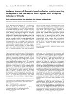
fabrication are schematically shown in Figure 1. Electro-
chemical impedance measurements were carried out
using a potentiostat (IM6 ZAHNER) equipped with a fre-
quency response analyzer (Thales) in the frequency range
of 0.1 Hz–1,000 kHz. The results were analyzed with an
equivalent circuit model for interpreting the characteris-
tics of the DSSCs. Incident photon-to-current conversion
efficiency (IPCE) of DSSCs was measured using PV Mea-
surements Inc. (Model QEX7) with bias illumination
with reference to the calibrated silicon diode.
The surface morphologies of the TiO
2
thin films
before and aft er SHI irradiation w ere studied by field-
emission scanning electron microscopy (JEOL-JSM
6330F). The crystalline phases of the TiO
2
films were
determined by X-ray diff raction (XRD) using a diffract-
ometer (Rigagu Denki Japan) with CuKa radiation. The
conductivity of the samples was studied via the two-
probe method.
Results and Discussion
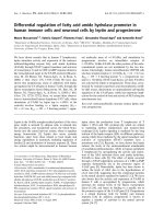
Figure 2 shows the X-ray diffraction spectr a of the ESD
pristine and the SHI-irradiated TiO
2
layers. Hereafter,
the SHI-irradiated TiO
2
layer is referred to as a layer
formed by the ESD first and subsequently SHI-irradiated
techniques. The characteristic peak observed at ~25.3°
in both t he films indicated the presence of an anatase
phase of TiO
2
(JCPDS 21-1272). The increase in the
relative peak intensities observed in the SHI-irradiated
sample shows that the SHI irradiation induced crystalli-
zation when compared to the as-prepared pristine ESD
TiO
2
films. The average grain siz e of the SHI-irradiated
TiO
2
films was found to be about 47 nm as estimated
from Scherrer’s equation. The significant additional peak
exhibited in the SHI-irradiated sample is not clearly
understood.
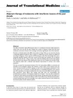
Surface morphologies of the pristine and the SHI-
irradiated TiO
2
films are presented in Figure 3. The
electrosprayed TiO
2
films reveal an aggregation pattern,
and t he spherical particles form an interconnected por-
ous framew ork of nano-sized building blocks (Figure 3).
The observed nano-aggregated particles may be ascribed
to the existence of a Coulumbic force lower than the
stretching force resulting from weak repulsion between
adjacent spray droplets. Under SHI irradiation, these
nano-aggregated TiO
2
particles melted and solidified on
the FTO substrate and consequently formed a rather
Figure 1 Schematic of a electrostatic spray deposition of TiO
2
compact layer, b SHI-irradiated TiO
2
compact layer and,
c SHI-irradiated TiO
2
compact layer assisted DSSCs.
Figure 2 X-ray diffraction spectra.(Notethat*indicatedin the
XRD spectra is indicated the crystalline contribution from FTO
substrate.) Standard peak position (JCPDS 21-1272) of the TiO
2
anatase phase is given in vertical lines.
Sudhagar et al. Nanoscale Res Lett 2011, 6:30
/>Page 3 of 7
flat, nonporous structure with the FTO layer (see
Figure 3). T his results in a compact interface at FTO/
TiO
2
for both blocking electron recombination and
increasing electron ic transport. The fragmentation of
the aggregated particles into smaller grains under SHI
irradiation can be explained by a thermal spike model. If
a large amount of energy is deposited by the projectile
ions to the electronic subsystem of the target material,
this energy can be shared among electrons by electron–
electron coupling and later transferred quickly to the
surrounding lattice through electron–phonon coupling.
Thus, a sudden temperatureriseonthetimescaleof
10
-12
s along the ion track resulted in a molten state.
The subsequent heat transfer to the surrounding lattice
results in resolidification of this molten liquid phase.
If this cooling rate s lows to a critical value, n ucleation
of crystalline phases can be expected along the ion tra-
jectory [28,29]. Therefore, we speculate that the sur face
of the TiO
2
particles may undergo an ion-beam-induced
molten state in a short duration of time (10
-12
s). These
molten state particles were attached with FTO substrate,
enhancing the inter-particle connectivity (compact) to
improve the conductivity of the film. The measured
conductivity of the pristine and the SHI-irradiated TiO
2
films found to be 2.31 × 10
-2
and 1.2 Scm
-1
, respectively,
indicating large improvement in the electron conductiv-
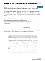
ity. Cross-sectional SEM images of the p ristine and the
SHI-irradiated TiO
2
films are illustrated in Figure 4.
Figure 4b suggests that the pristine ESD TiO
2
layer has
nano-aggregates and an inhomogeneous interface (con-
tact) with the FTO layer, mostly due to the removal of
polymer templates from ESD coating during sintering
treatment. The observed inhomogeneous TiO
2
/FTO
interface in the pristine sample was further compressed
by SHI irradiation using O
2
ions. This interface modifi-
cation was confirmed by Figure 4c, showing that
the TiO
2
particles adhered well to the FTO layer. The
thickness of the pristine film, ~1.1 μm, was reduced to
~0.67 μm af ter O ion irradiation. This is ascrib ed to the
comp act nature of TiO
2
film formed by SHI irradiation.
It is noteworthy to mention that improving the compact
nature of the TiO
2
blocking layer upon SHI irradiation
can facilitate electron transport and also reduce electron
recombination back to the electrolyte.
As shown in Figure 5, the ESD TiO
2
blocking layer
DSSC (pristine cell) shows higher IPCE (maximum up
to about ~53% at 530–540 nm) than the reference cell
over the whole range of light wavelengths. This clearly
demonstrates a ~16% improvement in external quantum
efficiency from reducing the electron losses at
Figure 3 Scanning electron microscopy images of pristine and
O
2
ion-irradiated TiO
2
compact layer.
Figure 4 Cross-sectional FE-SEMimagesofabareFTO
substrate, b pristine TiO
2
/FTO, and c O
2
ion-irradiated TiO
2
/
FTO. The thickness of the pristine and irradiated TiO
2
was about 1.1
and 0.67 μm, respectively. (Inset: images in 100 nm scale.)
Sudhagar et al. Nanoscale Res Lett 2011, 6:30
/>Page 4 of 7
FTO/TiO
2
interfaces. It appears that the ESD is more
efficient than the spin coating in terms of improving
IPCE due to the formation of continuous films. Further,
substantial improvement in IPCE was identified at lower
wavelengths (380 –420 nm), attributable to the SHI irra-
diationontheTiO
2
blocking layer. The IPCE can be
rationalized using the following relation [30],
IPCE
()
= A
inj coll
(3)
where A is the absorptivity indicating the fraction of
incident light absorbed by the dye molecules, j
inj
is the
injection efficiency of dye molecules into the TiO
2
con-
duction band, and h
coll
is the collection efficiency. The
parameters A and j
inj
are directly related to dye loading
on the TiO
2
surface. In the present work, we have con-
trolled similar dye loading in the reference,thepristine
and the SHI-irradiated electrodes , as verified with a dye
removal test using 1 M aqueous NaOH sol ution. There-
fore, A and j
inj
, of all these samples can be treated to
be equal, and the change in the IPCE is related to the
improvement in h
coll
. This improvement in h
coll
under
SHI irradiati on can be ascribed to (a) better adhesion of
the TiO
2
blocking layer with the TCO substrate and (b)
enhanced conta ct among TiO
2
particles. Hence, it is
expected that the SHI-irradiated blocking layer may
result in higher photoconversion efficiency.
Figure 6 shows the photocurrent density–voltage (J-V)
characteristics measured under 1 sun (100 mW cm
-2
AM 1.5) and dark conditions. The photovoltaic para-
meters were estimated from Figure 6 and are summar-
ized in Table 1. The photocurrent density (J
sc
)was
increased from 8.9 to 12.2 mA cm
-2
, and the overall effi-
ciency (h) was markedly improved from 3.8 to 5.1% by
replacing the ESD TiO
2
compa ct layer, compared to the
conventionally spin-coated blocking layer. This might be
attributed to the highly compact nature of the ESD
films, which provide more effective pathways for elec-
trons. As a result, electrons can be collected faster at
the TCO and transferred to the external circuit, result-
ing in improvement in the photovoltaic performance.
However, there is no appreciable change in the open
circuit voltage (V
oc
) between these sampl es. When the
ESD cell was treated with SHI irradiation, the open cir-
cuit voltage was further improved from 0.60 to 0.63 V,
and consequently, the overall energy conversion effi-
ciency improved from 5.1 to 5.5%. This may be because
of the SHI irradiation, which melted TiO
2
particles and
thereby improved electrical contact with the FTO sub-
strate (denser and more compact) and among TiO
2
par-
ticles. This clearly demonstrates that the SHI irradiation
enhances the bl ocking effect of electron recombin ation
and creates a facilitating effect on electron transport.
A comparison of dar k currents between the investi-
gated cells provides qualitative information about the
electron recombination process [31]. In DSSCs, prevent-
ing the recapture of photoinjected electrons by I
3
-
is
vital to obtain a high open circuit photovoltage. By
inserting the blocking layer between the FTO substrate
and the TiO
2
mesoporous layer, the reaction possibilities
of I
3
-
with the photoinjected electrons on the FTO sub-
strate are significantly hindered, as demonstrated by the
reduced dark current [31]. Here, the dark current–
voltage curves of the DSSCs using different blocking
layers are presented in the lower part of Figure 6. The
less dark current observed in the SHI-irradiated cell
Figure 5 IPCE spectra of DSSCs using different TiO
2
blocking
layers.
Figure 6 J-V measurements under a light illumination (100 mW
cm
-2
) along with b dark condition (lower part of the spectrum).
Table 1 Influence of TiO
2
blocking layer on photovoltaic
parameters of DSSCs
Sample V
oc
(V) J
sc
(mA cm
-2
) F.F (%) Efficiency (%)
Reference 0.59 8.9 71.9 3.8
Pristine 0.60 12.2 69.3 5.1
O
2
ion irradiated
(1 × 10
13
ions/cm
2
)
0.63 12.3 69.9 5.5
Sudhagar et al. Nanoscale Res Lett 2011, 6:30
/>Page 5 of 7
compared with the pristine cell may be attributed to the
better electrical contact between the blocking lay er and
the FTO substrate, and the compact nature of the
blocking lay er as well. Furthermore, during SHI irradia-
tion, it is expected that Sn
4+
particles from the FTO
layermayfusewiththeTiO
2
layer occupying the oxy-
gen vacancies in TiO
2
, thus lowering the Fermi level of
TiO
2
. For instance, the Fermi level position of the
Sn-doped TiO
2
layer is lower than that of the TiO
2
mesoporous layer, which is f avorable for fast electron
injection from mesoporous TiO
2
particles to the con-
ducting substrate [32].
Electrochemical impedance spectroscopy (EIS) pro-
vides valuable information on the k inetics of electron
transport in the DSSCs with deeper understanding of
the interfacial reactions at FTO/TiO
2
[33] and there-
fore was employed to decipher the blocking layer effect
in DSSCs. Figure 7 shows the Nyquist plots of the
electrochemical impedance spectra. Their equivalent
circuit is given as an inset in the figure. The charge
transfer resistances R
CT1
and R
CT2
represent the resis-
tances at the Pt/FTO and TiO
2
/dye/electrolyte inter-
faces, respectively. The electrochemical parameters
were estimated by fitting experimental data with the
equivalent circuit ( inset of Figure 7) [34] and are sum-
marized in Table 2.
The series resistance, R
s
, was decreased markedly in
the ca se of the pristine and O ion-irradiated elect rodes,
compared to t he reference elec trode. This is mostly
associated with better electron transfer through the
blocking layer due to better contact and better adhesion.
The R
CT2
value for SHI cells was increased markedly
compared to the reference and thepristineelectrodes.
The increased R
CT2
value may be mostly due to the fast
electro n transfer through the blocking layer. Hence , the
increased electron transferleadstoloweringelectron
concentration of TiO
2
mesoporous particles, which is
responsible for observed high R
CT2
(57.3 Ω)valuesin
the O ion-irradiated sample.
The results described above suggest that contact
among nanoparticles and the adhesion properties of a
blocking layer with an FTO substrate may improve the
performance of dye-sensitized solar cells. Further studies
using different ion energies and fluence may further
explain the role of electronic energy loss on these
devices and allow development of precise control of the
blocking layer.
Conclusions
An electrostatic spray deposition (ESD) tech nique fol-
lowed by SHI irradiation using 100 MeV oxygen ions
resulted in the formation of an efficient, dense TiO
2
blocking layer between the TiO
2
particle layer and the
TCO substrate. The blocking layer promotes charge
transportfromtheTiO
2
layer to the TCO substrate by
modifying the TCO/TiO
2
interfaces and causes effective
electri cal contact between the two layers. The formation
of an effective, compact blocking layer was possible due
to instantaneous surface melting of the ESD TiO
2
nano-
particles associated with a local temperature rise upon
oxygen ion irradiation. Energy conversion efficiency was
improved to a large extent ( h = 5.5%), compared to that
of the conventional blocking layer (h =3.8%),mainly
due to the increase in electron transport through the
blocking layer, resulting from better c ontact among
TiO
2
nanoparticles and better adhesion with the TCO
substrate.
Acknowledgements
We thank Dr. A. Roy, Director, Inter-University Accelerator Centre, New Delhi,
India for providing us beam time for SHI irradiation. This work was
supported by the Engineering Research Center Program through a National
Research Foundation of Korea (NRF) grant funded by the Ministry of
Education, Science and Technology (MEST) (2010-0001842) and also by the
World Class University (WCU) program (No. R31-2008-000-10092).
Author details
1
Center for Next Generation Dye-Sensitized Solar Cells, WCU Program,
Department of Energy Engineering, Hanyang University, Seoul, 133-791,
South Korea.
2
Inter-University Accelerator Centre, Aruna Asaf Ali Marg, New
Delhi, 110 067, India.
3
School of Chemical and Biological Engineering, Seoul
National University, Seoul, South Korea.
Figure 7 Nyquist spectra (measured under light illumination
(100 mW cm
-2
)) of DSSCs. The inset represents the impedance
spectra expanded in the high frequency ranges. The scattered
points are experimental data, and the solid lines are the fitting
curves.
Table 2 Influence of TiO
2
blocking layer on
electrochemical parameters of DSSCs
Sample Rs (Ω)R
CT1
(Ω)R
CT2
(Ω)
Reference 20.3 6.7 41.9
Pristine 13.6 8.6 39.8
O
2
ion-irradiated (1 × 10
13
ions/cm
2
) 13.9 7.9 57.3
Sudhagar et al. Nanoscale Res Lett 2011, 6:30
/>Page 6 of 7
Received: 24 June 2010 Accepted: 14 August 2010
Published: 16 September 2010
References
1. Gratzel M: Nature 2001, 414:338.
2. Quintana M, Edvinsson T, Hagfeldt A, Boschloo G: J Phys Chem C 2007,
111:1035.
3. Fukai Y, Kondo Y, Mori S, Suzukia E: Electrochem Comm 2007, 9:1439.
4. Cameron PJ, Peter LM: J Phys Chem B 2003, 107:14394.
5. Durrant JR, Haque SA, Palomares E: Coord Chem Rev 2004, 248:1247.
6. Cameron PJ, Peter LM: J Phys Chem 2005, 109:7392.
7. Xia J, Masaki N, Jiang K, Yanagida S: J Phys Chem C 2007, 111:8092.
8. Zhang Y, Wu L, Li Y, Xie E: J Phys D Appl Phys 2009, 42:085105.
9. Jung HS, Lee J-K, Nastasi M, Lee S-W, Kim JY, Park JS, Hong KS: Langmuir
2005, 21:10332.
10. Law M, Greene LE, Radenovic A, Kuykendall T, Liphardt J, Yang P: J Phys
Chem B 2006, 110:22652.
11. Nguyen V, Lee H-C, Khan MA, Yang O-B: Sol Energy 2007, 81:529.
12. Hart JN, Menzies D, Cheng Y-B, Simon GP, Spiccia L, Chimie CR: 2006, 9:622.
13. Papageorgiou N, Maier WF, Grätzel M: J Electrochem Soc 1997, 144:876.
14. Hossain MF, Biswas S, Takahashi T: Thin Solid Films 2008, 517:1294.
15. Waita SM, Aduda BO, Mwabora JM, Niklasson GA, Granqvist CG, Boschloo G:
J Electroanal Chem 2009, 637:79.
16. Peng B, Jungmann G, Jager C, Haarer D, Schmidt H-W, Thelakkat M: Coord
Chem Rev 2004, 248:1479.
17. Tachibana Y, Umekita K, Otsuka Y, Kuwabata S: J Phys D Appl Phys 2008,
41:102002.
18. Zhang Y, Wu L, Xie E, Duan H, Han W, Zhao J: J Power Sour 2009, 189:1256.
19. Chen CH, Kelder EM, Schoonman J: Thin Solid Films 1999, 342:35.
20. Fujihara K, Kumar A, Jose R, Ramakrishna S, Uchida S: Nanotechnology 2007,
18:365709.
21. Singh HK, Agarwal DC, Chavhan PM, Mehrad RM, Aggarwal S, Kulriya PK,
Tripathi A, Avasthi DK: Nucl Instrum Methods Phys Res Sect B Beam Interact
Materials Atoms .
22. Kumar V, Kumar R, Locha SP, Singh N: Nucl Instr Meth B 2007, 262:194.
23. Thakurdesai M, Kanjilal D, Bhattacharyya V: Semicond Sci Technol 2009,
24:085023.
24. Zeigler JF, Biersack JP, Littmark U: The Stopping and Range of Ions in
Solids. Pergamon, New York; 19851.
25. [www.srim.org/].
26. Chandramohan S, Sathyamoorthy R, Sudhagar P, Kanjilal D, Kabiraj D,
Asokan K, Ganesan V, Shripathi T, Deshpande UP: Appl Phys A 2009, 94:703.
27. Chena W, Suna X, Caia Q, Weng D, Lia H: Electrochem Commun 2007, 9:382.
28. Trinkaus H, Ryazanov AI: Phys Rev Lett 1995, 74:5072.
29. Szenes G: Phys Rev B 1995, 51:8026.
30. Nazeeruddin MK, Kay A, Rodicio I, Humphry-Baker R, Mueller E, Liska P,
Vlachopoulos N, Graetzel M: J Am Chem Soc 1993, 115:6382.
31. Ito S, Liska P, Comte P, Charvet R, Pechy P, Bach U, Schmidt-Mende L,
Zakeeruddin SM, Kay A, Nazeeruddin MK, Grätzel M: Chem Commun 2005,
4351.
32. Cao Y, He T, Chen Y, Cao Y: J Phys Chem C 2010, 114:3627.
33. Fabregat-Santiago AF, Bisquert J, Palomares E, Otero L, Kuang D,
Zakeeruddin SM, Grätzel M: J Phys Chem C 2007, 111:6550.
34. Wang Q, Moser JE, Grätzel M: J Phys Chem B 2005, 109:14945.
doi:10.1007/s11671-010-9763-2
Cite this article as: Sudhagar et al.: Efficient Performance of Electrostatic
Spray-Deposited TiO
2
Blocking Layers in Dye-Sensitized Solar Cells after
Swift Heavy Ion Beam Irradiation. Nanoscale Res Lett 2011 6:30.
Submit your manuscript to a
journal and benefi t from:
7 Convenient online submission
7 Rigorous peer review
7 Immediate publication on acceptance
7 Open access: articles freely available online
7 High visibility within the fi eld
7 Retaining the copyright to your article
Submit your next manuscript at 7 springeropen.com
Sudhagar et al. Nanoscale Res Lett 2011, 6:30
/>Page 7 of 7