Báo cáo hóa học: " Research Article Design of Vertically Aligned Binocular Omnistereo Vision Sensor" pptx
Bạn đang xem bản rút gọn của tài liệu. Xem và tải ngay bản đầy đủ của tài liệu tại đây (11.32 MB, 24 trang )
Hindawi Publishing Corporation
EURASIP Journal on Image and Video Processing
Volume 2010, Article ID 624271, 24 pages
doi:10.1155/2010/624271
Research Article
Desig n of Vertically Aligned Binocular Omnistereo Vision Sensor
Yi-ping Tang,
1
Qing Wang,
2
Ming-li Z ong,
2
Jun Jiang,
2
and Y i-hua Zhu
2
1
College of Information Engineering, Zhejiang University of Technology, Hangzhou 310023, China
2
College of Computer Science and Technology, Zhejiang University of Technology, Hangzhou 310023, China
Correspondence should be addressed to Qing Wang,
Received 30 November 2009; Revised 13 May 2010; Accepted 24 August 2010
Academic Editor: Pascal Frossard
Copyright © 2010 Yi-ping Tang et al. This is an open access article distributed under the Creative Commons Attribution License,
which permits unrestricted use, distribution, and reproduction in any medium, provided the original work is properly cited.
Catadioptric omnidirectional vision sensor (ODVS) with a fixed single view point is a fast and reliable single panoramic visual
information acquisition equipment. This paper presents a new type of binocular stereo ODVS which composes of two ODVS with
the same parameters. The single view point of each ODVS is fixed on the same axis with face-to-face, back-to-back, and faceto-
back configuration; the single view point design is implemented by catadioptric technology such as the hyperboloid, constant
angular resolution, and constant vertical resolution. The catadioptric mirror design uses the method of increasing the resolution
of the view field and the scope of the image in the vertical direction. The binocular stereo ODVS arranged in vertical is designed
spherical, cylindrical surfaces and rectangular plane coordinate system for 3D calculations. Using the collinearity of two view
points, the binocular stereo ODVS is able to easily align the azimuth, while the camera calibration, feature points match, and other
cumbersome steps have been simplified. The experiment results show that the proposed design of binocular stereo ODVS can solve
the epipolar constraint problems effectively, match three-dimensional image feature points rapidly, and reduce the complexity of
three-dimensional measurement considerably.
1. Introduction
Designing vision sensors is critical for developing, sim-
plifying, and improving several applications in computer
vision and other areas. Some traditional problems like scene
representation, surveillance, and mobile robot navigation are
found to be conveniently tackled by using different sensors,
which leads to much more effort made in researching and
developing omnidirectional vision systems, that is, systems
capable of capturing objects in all directions [1–11].
An omnidirectional image has a 360-degree view around
a viewpoint, and in its most common form, it can be
presented in a cylindrical or spherical surface around
the viewpoint. Usually, an omnidirectional image can be
obtained either by an image mosaicing technique or by
an omnidirectional camera. An omnidirectional camera is
widely used in practice, since it is able to capture real-
time three-dimensional space of the scene information
and can avoid the complexities arising from dealing with
image mosaicing. In this paper, kinds of vertically aligned
binocular (V-binocular) omnistereo, which are composed
of a pair of hyperbolic-shaped mirrors, a constant angular
resolution mirror, or a constant vertical resolution mirror,
are investigated. Moreover, critical issues on omnidirectional
stereo imaging, structural design, epipolar geometry, and
depth accuracy are discussed and analyzed.
The binocular stereoscopic 3D measurement and 3D
reconstruction technology based on computer vision are
new technology with great potential in development and
practice, which can be widely used in such areas as industrial
inspection, military reconnaissance, geographical survey-
ing, medical cosmetic surgery, bone orthopaedics, cultural
reproduction, criminal evidence, security identification, air
navigation, robot vision, virtual reality, animated films,
games, and so on. Besides, it has become a hot spot in the
computer vision research community [12–14].
Stereo vision is based on binocular parallax principle of
the human eyes [15–18] to perceive 3D information, which
imitates the method used by human being to apperceive
distance in binocular clues. Distance between objects is
obtained from binocular parallax of the two images, respec-
tively, captured by two eyes for the same object, which makes
a stereo image vivid as depth information is include in
the image. There are two main shortcomings in the stereo
2 EURASIP Journal on Image and Video Processing
vision technology: (1) camera calibration, matching, and
reconstruction are still not resolved perfectly, and (2) it is not
able to capture panoramic view and to make people feel being
in the scene personally since it is object-centered and with
narrow-view; that is, it only captures a small part of the scene.
Fortunately, the second shortcoming is overcome by the
ODVS technology [19], a viewer-centered technology, which
eliminates the narrow-view problem so that a panoramic
view is gained.
Currently, there exist some challenges in binocular stereo
vision, which belong to vision ill-posed problems including
camera calibration, feature extraction, stereo image match-
ing, and so forth. For calibration, it is well known that upon
camera calibration is set, focal length is fixed, which leads
the depth of the captured image to be unchanged and only
within limited range. In other words, camera calibration is
needed to be reset if we need to change the depth. Another
disadvantage of calibration is that changing parameters are
avoided in a variety of movement in 3D visual measurement
system [20–22]. These disadvantages limit the application of
the binocular stereo vision. Additionally, disadvantages in
feature extraction and stereo image matching are mainly as
follows. The processes of various shapes from X incur coor-
dinate transformation to be performed many times, which
produces extraneous calculation and makes it impossible to
conduct real-time processing. Besides, there exists a high
mismatching probability in matching corresponding points,
yielding high rate of matching errors and reducing matching
accuracy. Nowadays, 3D visual matching is a typical ill-posed
calculation and it is difficult to get 3D match unambiguously
and accurately [23].
Advances in ODVS technology in recent years provide a
new solution for acquiring a panoramic picture of the scenes
in real time [24]. The feature of ODVS with wide range
of vision can be used to compress the information of the
hemispheric vision into an image including a great volume
of information. On the other hand, ODVS can be freely
placed to get a scene image. ODVS establishes a technical
foundation for building a 3D visual sensing measurement
system.
There are many types of omnidirectional vision system,
which based on rotating cameras, fish-eye lens or mirrors.
This paper is mainly concerned with the omnidirectional
vision systems combining cameras with mirrors, normally
referred as catadioptric systems in the optics domain,
especially in what concerns the mirror profile design. The
shape of the mirror determines the image formation model
of a catadioptric omnidirectional camera. In some cases, one
can design the shape of the mirror in such a way that certain
world-to-image geometric properties are preserved, referred
as linear projection properties.
2. Motivation of the Research
The use of robots is an attractive option in places where
human intervention is too expensive or hazardous. Robots
have to explore the environment using a combination of
their onboard sensors and eventually process the obtained
Hyperbola
Figure 1: The hyperbola formed by a plane intersecting both
nappes of a cone [25].
Camera
Sensor
First principal point
Lens
Mirror
F
D
L
Figure 2: Omnidirectional camera and lens configuration [26].
data and transform it in useful information for further
decisions or for human interpretation. Therefore, it is critical
to provide the robot with a model of the real scene or with
the ability to build such a model by itself. Our research is
motivated by the construction of a visual and nonintrusive
environment model.
The omnidirectional vision enhances the field of view of
traditional cameras by using special optics and combinations
of lenses and mirrors. Besides the obvious advantages offered
by a large field of view, in robot navigation the necessity of
employing omnidirectional sensors also stems from a well-
known problem in computer vision: the motion estimation
algorithms may mistake a small pure translation of the
camera for a small rotation, and the possibility of error
increases if the field of view is narrow or the depth variations
in the scene are small. An omnidirectional sensor can
eliminate this error since it receives more information for the
EURASIP Journal on Image and Video Processing 3
0
5
10
15
20
25
30
−33.5 −24.5 −15.5 −6.52.511.520.529.5
SVP
(a)
SVP
(b)
SVP
F
C
(c)
Figure 3: Hyperbolic-shaped mirror. (a) Hyperbolic profile with the parameters a = 51.96 and b = 30. The dot represents the focal point of
the mirror, that is, the SVP of the sensor. (b) The same hyperbolic mirror represented in 3D space. (c) Isotropic of hyperbolic mirror.
aa
2c
Figure 4: The relat ion between the parameters a and c and the
hyperbolic profile [25].
same movement of the camera than the one obtained by a
reducedfieldofviewsensor.
According to different practical application cases, three
kinds of coordinate system on vertically aligned binocular
omnistereo vision sensor are proposed, namely, spherical
surface sensing type, cylindrical surface sensing type, and
orthogonal coordinates sensing type. For spherical surface
sensing type, it is desired to ensure uniform angular reso-
lution as if the camera had a spherical geometry. This sensor
has interesting properties (e.g., ego-motion estimation). For
cylindrical surface sensing type, this design constraint aims
to the goal that objects at a (prespecified) fixed distance from
the camera’s optical axis will always have the same size in the
image, independent of its vertical coordinates. Orthogonal
coordinates sensing type ensures that the ground plane is
imaged under a scaled Euclidean transformation.
It is significant to build a uniform coordinate system
for 3D stereo vision so that ill-posed calculation is avoided.
P
m
R
t
z
h
F
1
r
2c
f
F
2
r
i
P
i
Figure 5: The relation between the size of the sensor and the
intrinsic parameters of the omnidirectional camera.
Motivated by this, we investigate designing binocular stereo
ODVS and build a uniform spherical coordinate system,
in which computational geometry is used in object depth
calculation, the 3D visual matching, and the 3D image
reconstruction. The main contributions of this paper are
as follows: (1) two omnidirectional vision equipment are
seamlessly combined to capture objects without shelter; (2)
the overlay vision area in the designed sensors (which is
generated from visual fields of two ODVSs being combined
in back-to-back configuration for spherical surface 3D stereo
vision, face-to-face configuration for cylindrical surface 3D
stereo vision, or face-to-back configuration for photogram-
metry), makes it possible for a binocular stereo ODVS to
perceive, match, and capture stereoscopic images at the same
4 EURASIP Journal on Image and Video Processing
R
t
2a
Z
2b
r
Figure 6: High vertical FOV hyperbolic mirror suitable for
binocular omnistereo. The parameters of the mirror are a
= 19, b =
10, and R
t
= 25. The vertical FOV above the horizon is of 49.8
degrees.
V = (0, 0)
d
Mirror area
Mirror point
F
= (0, c)
C
Wor ld
u
Solid angle dw
Pixel area dA
Figure 7: The geometry to derive spatial resolution of catadioptric
system.
time; (3) a uniform Gaussian sphere coordinate system is
presented for image capturing, 3D matching, and 3D image
reconstruction so that computing models are simplified. All
the above contributions together with features of ODVSs
simplify the camera calibration and feature point matching.
3. Design of Catadioptric Cameras
Catadioptric cameras act like analog computers performing
transformations from 3D space to the 2D image plane
through the combination of mirrors and lenses. The mirrors
used in catadioptric cameras must cover the full azimuthal
FOV (Field of View) and thus are symmetric revolution
0.9
0.92
0.94
0.96
0.98
1
Normalized (δ
A
/δ
ω
)
0 50 100 150 200 250 300
Pixel
Hyperbola
Hyperbola
Figure 8: Resolution of ODVS having a perspective camera and an
hyperbolic mirror where a pinhole located at the coordinate system
origin d
= 0.
T
N
2
f
SC
Z
Firstly reflection mirror F
1
Secondary reflection mirror F
2
P
1
(t
1
, F
1
)
V
1
P
φ
θ
1
θ
2
V
2
N
1
P
2
(t
2
, F
2
)
Figure 9: Imaging principle of catadioptric of constant angular
resolution.
Firstly reflection mirror
Secondary reflection mirror
t
Z
Figure 10: Reflectors curvilinear figure solution.
EURASIP Journal on Image and Video Processing 5
L
N
2
f
S
C
Z
Firstly reflection mirror F
1
Secondary reflection mirror F
2
P
1
(t
1
, F
1
)
V
1
P
θ
1
θ
2
V
2
N
1
P
2
(t
2
, F
2
)
Figure 11: Imaging principle of catadioptric of constant vertical
resolution.
shapes, usually with conic profile. The cameras are first
classified with respect to the SVP (Single View Point)
property and then classified according to the mirror shapes
used in their fabrication. We focus on the omnidirectional
cameras with depth perception capabilities that are high-
lighted among the other catadioptric configurations. Finally,
we present the epipolar geometry for catadioptric cameras.
Catadioptrics are combinations of mirrors and lenses,
which arranged carefully to obtain a wider field of view than
the one obtained by conventional cameras. In catadioptric
systems, the image suffers a transformation due to the
reflection in the mirror. This alteration of the original image
depends on the mirror shape. Therefore, a special care was
given to the study of the mirror optical properties. There
are several ways to approach the design of a catadioptric
sensor. One method is to start with a given camera and
find out the mirror shape that best fits its constraints.
Another technique is to start from a given set of required
performances such as field of view, resolution, defocus blur,
and image transformation constraints and so forth, then
search for the optimal catadioptric sensor. In both cases, a
compulsory step is to study the properties of the reflecting
surfaces.
Most of the mirrors considered in the next sections
are surfaces of revolution, that is, 3D shapes generated
by rotating a two-dimensional curve about an axis. The
resulting surface therefore always has azimuthally symmetry.
Moreover, the rotated curves are conic sections, that is,
curves generated by the intersections of a plane with one or
two nappes of a cone as shown in Figure 1. For instance,
a plane perpendicular to the axis of the cone produces a
circle while the curve produced by a plane intersecting both
nappes is a hyperbola. Rotating these curves about their axis
of symmetry, a sphere and a hyperboloid are obtained.
An early use of a catadioptric for a real application
was proposed by Rees in 1970 [Rees, 1970]. He invented a
panoramic television camera based on a convex, hyperbolic-
shaped mirror shown in Figure 2.Twentyyearslater,once
again researchers focused their attention on the possibilities
offered by the catadioptric systems, mostly in the field of
robotics vision. In 1990, the Japanese team from Mitsubishi
Electric Corporation lead by Yagi [Yagi and Kawato, 1990]
studied the panoramic scenes generated using a conic
mirror-based sensor. The sensor, named COPIS 2, was used
to generating the environmental map of an indoor scene
from a mobile robot. The conic mirror shape was also used,
in 1995, by the researchers from the University of Picardie
Jules Verne, lead by Mouaddib. Their robot was provided
with an omnidirectional sensor, baptized SYCLOP 3, which
captures 360-degree images at each frame and was used for
navigation and localization in the 3D space [Pegard and
Mouaddib, 1996].
Since the mid-1990s of last century, omnidirectional
vision and its knowledge base have increasingly attracted
attention with the increase in the number of researchers
involved in omnidirectional cameras. Accordingly, new
mathematical models for catadioptric projection and con-
sequently better performing catadioptric sensors have
appeared.
Central catadioptric sensors are the class of these devices
having a single effective viewpoint [25]. The reason for a
single viewpoint is from the requirement for the generation
of pure perspective images from the sensed images. This
requirement ensures that the visual sensor only measures
the intensity of light passing through a projection center.
It is highly desirable that the omnidirectional sensor have
a single effective center of projection, that is, a single point
through which all the chief rays of the imaging system pass.
This center of projection serves as the effective pinhole (or
viewpoint) of the omnidirectional sensor. Since all scene
points are “seen” from this single viewpoint, pure perspective
images that are distortion free (like those seen from a
traditional imaging system) can be constructed via suitable
image transformation.
The omnidirectional image has different features from
the image captured by standard camera. Vertical resolution of
the transformed image has usually nonuniform distribution.
The circle which covers the highest number of pixels is
projected from the border of the mirror, which means that
the transformed image resolution is decreasing towards the
mirror center. If the image is presented to a human, a
perspective/panoramic image is needed so as not to appear
distorted. When we want to further process the image,
other issues should be carefully considered, such as spatial
resolution, sensor size, and ease of mapping between the
omnidirectional images and the scene.
The parabolic-shaped mirror is a solution of the SVP
constraint in a limiting case which corresponds to ortho-
graphic projection. The parabolic mirror works in the same
way as the parabolic antenna: the incoming rays pass through
the focal point and reflected parallel to the rotating axis of
the parabola. Therefore, a parabolic mirror should be used
in conjunction with an orthographic camera. A perspective
camera can also be used if it is placed very far from the
mirror so that the reflected rays can be approximated as
6 EURASIP Journal on Image and Video Processing
Table 1: ODVS composing vertically aligned binocular omnistereo.
Type Construction Depth Resolution SVP Isotropic VFOV
Single camera with single mirror Hyperbolic-shaped mirror no change yes yes yes
Single camera with two mirrors
Constant angular resolution mirror no Constant in spherical surface yes yes yes
Constant vertical resolution mirror no Constant in cylindrical surface yes yes yes
Table 2: Experement resluts of measuring depth between view point and object from 30 cm to 250 cm using V-binocular ODVS with face-
toface configuration in Figure 15(b).
Actual depth
(cm)
Up image plane
coordinates
C
up
(x
1
, y
1
)
Angle of
incidence φ
1
(degree)
Down image
plane coordinates
C
down
(x
2
, y
2
)
Angle of
incidence φ
2
(degree)
Depth
estimation
(cm)
Error ratio
(%)
30.00 300,34 57.84 300,40 55.82 31.04 3.47
40.00 301,39 65.04 301,54 62.70 41.36 3.39
50.00 301,59 69.54 301,66 68.21 52.52 5.03
60.00 301,57 72.96 301,72 70.84 62.08 3.47
70.00 298,62 75.03 298,79 73.80 72.74 3.91
80.00 300,67 77.04 300,83 75.44 82.85 3.56
90.00 299,70 78.22 299,87 77.04 92.52 2.80
100.00 299,73 79.38 299,90 78.22 102.46 2.46
110.00 300,76 80.52 300,92 78.99 112.27 2.06
120.00 299,78 81.27 299,93 79.38 118.97
−0.86
130.00 298,80 82.01 298,94 79.76 126.42
−2.75
140.00 302,81 82.37 302,99 81.64 144.47 3.20
150.00 298,82 82.74 298,99 81.64 147.89
−1.40
160.00 299,83 83.10 299,101 82.37 159.21
−0.49
170.00 298,83 83.10 298,102 82.74 163.36
−3.91
180.00 300,84 83.46 300,103 83.10 172.24
−4.31
190.00 301,86 84.18 301,103 83.10 182.00
−4.21
200.00 299,87 84.53 299,104 83.46 192.93
−3.54
210.00 298,87 84.53 298,106 84.18 205.24
−2.27
220.00 299,88 84.88 299,107 84.53 219.04
−0.44
230.00 298,88 84.88 298,107 84.53 219.07
−4.77
240.00 299,89 85.23 299,109 85.23 243.37 1.40
250.00 298,89 85.23 298,109 85.23 243.37
−2.65
Table 3: Experement resluts of measuring depth between view point and object from 100 cm to 1100 cm using V-binocular ODVS with
face-to-face configuration in Figure 15(b).
Actual depth
(cm)
Up image plane
coordinates
C
up
(x
1
, y
1
)
Angle of
incidence φ
1
(degree)
Down image
plane coordinates
C
down
(x
2
, y
2
)
Angle of
incidence φ
2
(degree)
Depth
estimation
(cm)
Error ratio
(%)
100.00 299,83 79.38 299,90 78.22 102.46 2.46
200.00 299,87 84.53 299,104 83.46 192.93
−3.54
300.00 299,91 85.93 299,110 85.58 273.4
−8.86
400.00 301,100 88.96 301,113 86.62 425.37 6.34
500.00 298,103 89.93 298,110 85.58 480.42
−3.92
600.00 302,104 90.25 302,111 85.93 608.52 1.42
700.00 300,104 90.25 300,112 86.27 668.99
−4.43
800.00 300,106 90.89 300,112 86.27 819.20 2.40
900.00 302,104 90.25 302,114 86.96 832.99
−7.45
1000.00 301,104 90.25 301,116 87.63 1099.15 9.91
1100.00 300,107 91.21 300,114 86.96 1264.88 14.99
EURASIP Journal on Image and Video Processing 7
O
g
p
A
X
x
z
h
u
Sensor plane
h(
u
)u
C
(a)
v
u
(b)
u
v
I
C
O
c
(c)
Figure 12: Single viewpoint catadioptric camera imaging model (a) perspective of the imaging process, (b) sensor plane, and (c) image
plane.
Table 4: Experement resluts of measuring depth between view point and object from 30 cm to 250 cm using V-binocular ODVS with back-
to-back configuration in Figure 16(b).
Actual depth
(cm)
Up image plane
coordinates
C
up
(x
1
, y
1
)
Angle of
incidence φ
1
(degree)
Down image
plane coordinates
C
down
(x
2
, y
2
)
Angle of
incidence φ
2
(degree)
Depth
estimation
(cm)
Error ratio
(%)
30.00 618,47 98.81 618,151 98.26 33.08 10.28
40.00 618,52 97.43 618,143 96.02 42.25 5.63
50.00 616,57 96.02 616,138 94.56 54.05 8.11
60.00 618,60 95.15 618,136 93.97 62.99 4.98
70.00 617,62 94.56 617,134 93.37 72.73 3.91
80.00 616,62 94.56 616,131 92.45 82.54 3.18
90.00 616,64 93.97 616,130 92.14 95.21 5.79
100.00 617,66 93.37 617,129 91.83 100.50 0.50
110.00 617,66 93.37 617,129 91.83 112.64 2.40
120.00 616,66 93.37 616,128 91.52 120.16 0.14
130.00 617,67 93.06 617,128 91.52 128.50
−1.15
140.00 616,67 93.06 616,127 91.21 138.44
−1.12
150.00 618,67 93.06 618,127 91.21 138.44
−7.71
160.00 619,68 92.76 619,127 91.21 149.68
−6.45
170.00 616,69 92.45 616,127 91.21 162.99
−4.12
180.00 619,69 92.45 619,126 90.89 179.38
−0.35
190.00 616,69 92.45 616,126 90.89 179.38
−5.59
200.00 617,70 92.14 617,126 90.89 198.92
−0.54
210.00 619,70 92.14 619,126 90.89 198.92
−5.28
220.00 618,71 91.83 618,124 90.25 298.44 35.65
230.00 617,71 91.83 617,124 90.25 298.44 29.76
240.00 616,71 91.83 616,124 90.25 298.44 24.35
250.00 617,71 91.83 617,124 90.25 298.44 19.38
8 EURASIP Journal on Image and Video Processing
Table 5: Experement resluts of measuring depth between view point and object from 100 cm to 1100 cm using V-binocular ODVS with
back-to-back configuration in Figure 16(b).
Actual depth
(cm)
Up image plane
coordinates
C
up
(x
1
, y
1
)
Angle of
incidence φ
1
(degree)
Down image
plane coordinates
C
down
(x
2
, y
2
)
Angle of
incidence φ
2
(degree)
Depth
estimation
(cm)
Error ratio
(%)
100.00 617,67 93.37 617,129 91.83 100.50 0.01
200.00 617,70 92.14 617,126 90.89 198.92
−0.54
300.00 617,71 91.87 617,123 89.93 359.08 19.69
400.00 617,72 91.40 617,120 88.96 462.75 15.69
500.00 617,73 91.12 617,118 88.30 645.85 29.17
600.00 617,70 92.14 617,124 90.25 969.43 61.57
700.00 617,71 91.83 617,124 90.25 1113.63 59.09
800.00 618,71 91.83 618,123 89.93 1316.21 64.53
900.00 617,71 91.83 617,129 91.83 1610.93 78.99
1000.00 618,72 91.52 618,122 89.61 2055.70 105.57
1100.00 617,72 91.52 617,125 90.72 2884.77 162.25
Table 6: Experement resluts of measuring depth between view point and object from 30 cm to 250 cm using V-binocular ODVS with face-
to-back configuration in Figure 17(b).
Actual depth
(cm)
Up image plane
coordinates
C
up
(x
1
, y
1
)
Angle of
incidence φ
1
(degree)
Down image
plane coordinates
C
down
(x
2
, y
2
)
Angle of
incidence φ
2
(degree)
Depth
estimation
(cm)
Error ratio
(%)
30.00 134,79 73.80 134,163 106.29 32.09 6.97
40.00 132,88 77.44 132,149 102.95 41.29 3.22
50.00 134,94 79.76 134,139 100.41 51.33 2.65
60.00 135,98 81.27 135,133 98.81 60.60 0.99
70.00 133,99 82.37 133,129 97.71 69.43
−0.81
80.00 132,103 83.10 132,126 96.87 77.42
−3.22
90.00 132,106 84.18 132,123 96.02 90.15 0.17
100.00 134,107 84.53 134,120 95.15 100.60 0.60
110.00 134,109 85.23 134,119 94.86 111.07 0.97
120.00 132,110 85.58 132,118 94.56 119.06
−0.78
130.00 135,111 85.93 135,117 93.97 133.05 2.34
140.00 134,112 86.27 134,117 93.97 139.02
−0.70
150.00 133,112 86.27 133,114 93.37 150.84 0.56
160.00 134,113 86.62 134,114 93.37 158.51
−0.93
170.00 133,113 86.62 133,113 93.06 165.98
−2.37
180.00 132,114 86.96 132,113 93.06 175.25
−2.64
190.00 134,114 86.96 134,112 92.76 184.47
−2.91
200.00 132,115 87.29 132,112 92.76 195.92
−2.04
210.00 132,115 87.29 132,111 92.45 207.59
−1.15
220.00 132,116 87.63 132,111 92.45 222.10 0.95
230.00 135,116 87.63 135,110 92.14 237.30 3.18
240.00 133,116 87.63 133,110 92.14 237.30
−1.12
250.00 134,116 87.63 134,109 91.83 254.85 1.94
parallel. Obviously, this solution would provide unacceptable
low resolution and has no practical value for binocular
omnistereo.
In summary, the great interest generated by catadioptric
is due to their specific advantages when compared to other
omnidirectional systems, especially VFOV, the price, and the
compactness.
EURASIP Journal on Image and Video Processing 9
Table 7: Experement resluts of measuring depth between view point and object from 100 cm to 1100 cm using V-binocular ODVS with
face-to-back configuration in Figure 17(b).
Actual depth
(cm)
Up image plane
coordinates
C
up
(x
1
, y
1
)
Angle of
incidence φ
1
(degree)
Down image
plane coordinates
C
down
(x
2
, y
2
)
Angle of
incidence φ
2
(degree)
Depth
estimation
(cm)
Error ratio
(%)
100.00 134,107 84.53 134,120 95.15 100.60 0.60
200.00 132,115 87.29 132,112 92.76 195.92
−2.04
300.00 134,115 87.24 134,100 88.96 298.73
−0.42
400.00 132,118 88.17 132,100 88.96 402.22 0.55
500.00 135,119 88.79 135,98 88.30 397.25
−20.55
600.00 133,119 88.79 133,98 88.30 397.25
−33.79
700.00 132,121 89.11 132,99 88.63 521.48
−25.50
800.00 135,121 89.11 135,102 89.61 985.49 23.19
900.00 135,122 89.75 135,100 88.96 972.43 8.048
1000.00 135,122 89.75 135,101 89.28 1154.48 15.45
1100.00 133,124 90.07 133,101 89.28 1752.78 59.34
g/h
x
s
q
g
p
X
S
3
z
h
h(
u
)u
C
u
Sensor plane
Figure 13: The mapping of a scene point X into a sensor plane to a
point u
for a hyperbolic mirror.
ω
(u
, v
)-opt.axis
(μ
, v
,1)
T
(μ
, v
, ω
)
T
1
ρ
θ
π
r
f (r
)
(p
, q
, s
)
T
Figure 14: The point (μ
, ν
, l)
T
in the image p lane π is trans-
formed by f (
·)to(μ
, ν
, ω
)
T
,thennormalizedto(p
, q
, s
)
T
with unit length, and thus projected on the sphere ρ [27, 28].
3.1. Design of Hyperbolic-Shaped Mirror. Let us consider the
hyperbolic-shaped mirror given in (1). An example of mirror
profile obtained by this equation is shown in Figure 3
z −
√
a
2
+ b
2
2
a
2
−
x
2
+ y
2
b
2
= 1.
(1)
The hyperbola is a function of two parameters a and b,
but also, these parameters can be expressed by parameters
c and k which determine the interfocus distance and the
eccentricity, respectively. The relation between the pairs a, b
and c, k is shown in (2). Figure 4 shows that the distance
between the tips of the two hyperbolic napes is 2a while the
distance between the two foci is 2c
a
=
c
2
k −2
k
, b
=
c
2
2
k
.
(2)
By changing the values of these parameters, the hyper-
bola changes its shape as well as the position of the
focal point. The positions of the foci of the two napes of
the hyperbola determine the size of the omnidirectional
sensor. The catadioptric sensor designed is used in binocular
omnistereo vision sensor and is required to have large vertical
angle α. Besides, image processing requires good resolution
and a good vertical angle of view.
It is obvious that the azimuth field of view is 360
◦
since
the mirror is a rotational surface upon the z axis. The vertical
view angle is a function of the edge radius and the vertical
distance between the focal point and the containing the rim
of the mirror. This relation is expressed in (3)whereR
t
is the
radius of the mirror rim and α is the vertical view angle of
the mirror
α
= arctan
h
R
i
+
π
2
.
(3)
Therefore, R
t
and h are the two parameters that bound
the set of possible solutions.
The desired catadioptric sensor must possess a SVP,
therefore, the pinhole of the camera model and the central
10 EURASIP Journal on Image and Video Processing
(a) (b)
Z
Y
AX
V
1
P
dc
B
V
2
(c)
(d)
Figure 15: Vertically aligned binocular omnistereo vision sensor by face-to-face configuration (a) design drawing, (b) real product image,
(c) vertically-aligned binocular omnistereo model in cylindrical surface, and (d) FOV of binocular omnistereo vision.
projection point of the mirror have to be placed at the two
foci of the hyperboloid, respectively. The relation between
the profile of the mirror and the intrinsic parameters of the
camera, namely, the size of the CCD and the focal distance,
is graphically represented in Figure 5.Here,P
m
(r
rim
, z
rim
)is
a point on the mirror rim, P
i
(r
i
, z
i
) is the image of the point
P
m
on the camera image plane, f is the focal distance of the
camera and h is the vertical distance from the focal point of
the mirror to its edge. Note that z
rim
= h and z
i
=−(2c + f ).
Ideally, the mirror is imaged by the camera as a disc with
circular rim tangent to the borders of the image plane.
Several constraints must be satisfied during the design
process of the hyperbolic mirror shape.
(i) The mirror rim must have the right shape so that the
camera is able to see the point P
m
. In other words,
the hyperbola should not be cut below the point P
m
which is the point that reflects the higher part of the
desiredfieldofview.
(ii) The points of the camera mirror rim must be on the
line
P
i
P
m
for an optimally sized image in the camera.
A study about the impact of the parameters a and b on
the mirrors’ profile was also conducted by T.Svobodaetal.
in [10]. Svoboda underlined the impact of the ratio k
= a/b
on the image formation when using a hyperbolic mirror.
(i) k>b/R
t
is the condition that the catadioptric
configuration must satisfy in order to have a field of
view higher than the horizon (i.e., greater than the
hemisphere).
(ii) k<(h +2c)/R
t
is the condition for obtaining
a realizable hyperbolic mirror. This requirement
implies finding the right solution of the hyperbola
equation.
(iii) k>[(h +2c)/4cb]
− [b/(h +2c)] prevents focusing
problems by placing the mirror top far enough from
the camera).
An algorithm was developed in order to produce hyper-
bolic shapes according to the application requirements and
taking into account the above considerations related to
the mirror parameters. A mirror is presented in Figure 6
providing a vertical FOV above the horizon of 49.8 degree.
If it needs a higher vertical FOV, a sharper mirror must be
rebuilt.
3.2. Hyperbolic-Shaped Mirror Resolution. We assume the
conventional camera has the pinhole distance u and its
EURASIP Journal on Image and Video Processing 11
(a) (b)
P
r
Φ
β
P
(c)
(d)
Figure 16: vertically-aligned binocular omnistereo vision sensor by back-to-back configuration (a) design drawing, (b) real product image,
(c) vertically aligned binocular omnistereo model in spherical surface, and (d) FOV of binocular omnistereo vision.
optical axis is aligned with the mirror axis. The situation
is depicted on the picture (Figure 7). Then, the definition
of the resolution is follows. Consider an infinitesimal area
dA on the image plane. If this infinitesimal pixel images an
infinitesimal solid angle dv of the world, the resolution of
the catadioptric sensor as a function of the point on the
image plane and at the center of the infinitesimal area dA
is dv/dA. The resolution of the conventional camera can
be written as dw/dA. The more detailed derivation of these
relations is presented in the Baker’s and Nayar’s work [27].
The resolution of the catadioptric camera is the resolution
of conventional camera used to construct it multiplied by a
factor (r
2
+ z
2
)/((c − z)
2
+ r
2
)). Hence, we have
dA
dv
=
r
2
+ z
2
(
c
− z
)
2
+ r
2
dA
dw
,(4)
where (r, z) is the point on the mirror being imaged.
The multiplication factor in (4) is the square of the
distance from the point (r, z) to the effective viewpoint v
=
(0, 0), divided by the square of the distance to the pinhole
F
= (0, c). Let d
v
denote the distance from the viewpoint to
(r, z)andd
p
the distance of (r, z) from the pinhole. Then, the
factor in (4)isd
2
v
/d
2
p
. For hyperboloid, we have d
p
−d
v
= K
h
,
where the constant K
h
satisfies 0 <K
h
<d
p
. Therefore, the
factor is
1 −
K
h
d
p
2
,
(5)
Which increases as d
p
increases and d
v
increases. It
means that the factor in (4) increases with r for the
hyperbolic mirror for which it was derived. Hence, the
catadioptric sensor constructed with a hyperbolic mirror and
the uniform resolution conventional camera will have their
highest resolution around the periphery.
Figure 8 illustrates the resolution across a radial slice of
the imaging plane. The curves have been normalized with
respect to magnification. It can be seen that resolution drops
drastically beyond some distance from the image center.
Resolution is parameterized by the geometry of the
mirror, the location of the entrance pupil, and the focal
length of the lens used. Given an appropriate resolution
curve, we can “fit” the right parameters in the model
that most closely approximates the required curve. In the
most generic setting, we could let resolution characteristics
completely dictate the reflector’s shape (not restricted to
conic reflectors). It should, however, be noted that by fixing
resolution the sensor may not maintain a single viewpoint.
Depending on the application at hand, this may or may not
be critical.
To design a mirror profile to match the sensor’s reso-
lution is to satisfy the Binocular Omnistereo Vision Sensor
application constraints, in terms of desired image properties,
such as constant angular resolution and constant vertical
resolution.
12 EURASIP Journal on Image and Video Processing
(a) (b)
A
dc
B
V
1
V
2
P
Z
X
Y
(c)
(d)
Figure 17: Vertically aligned binocular omnistereo vision sensor by face-to-back configuration (a) design drawing, (b) real product image,
(c) vertically aligned binocular omnistereo model in orthogonal coordinates, and (d) FOV of binocular omnistereo vision.
3.3. Design of Constant Angular Resolution Mirror. In order
to ensure that the image of transition region of two ODVSs is
continuous, ODVS is designed by using the average angle.
In other words, there is a linear relation between points
on imaging plane and incident angle. Constant angular
resolution mirror can be used to obtain spherical surface
with constant resolution around the viewpoint. The spherical
surface may be described in terms of r, z, the variables of
interest in (6), simply as
r
= C × cos
φ
, z = C × sin
φ
,
(6)
where C is the distance of light source P and SVP, and φ is the
angle between the first incident light V1 and the spindle Z.
The design of the constant angular resolution can be
reduced to the design of curve of catadioptric mirror [29]. As
shown in Figure 9, the incident light V1 from a light source P
reflects on the main mirror reflection (t1, F1); the reflected
light V2 reflects another time after it reflects on the secondly
mirror reflection (t2, F2); the reflected light V3 enters into
the camera lens with the angle of θ1andprojectedtoits
image on the camera.
According to imaging principle, the angle between the
first incident light V1 and the spindle Z is φ, the angle
between the first reflected light V2 and the spindle Z is θ2,
the angle between the tangent through P1(t1, F1) and the
spindle T is σ, and the angle between the normal and the
spindle Z is ε; the angle between the secondary reflected light
V3 and the main axis Z is θ1, the angle between the tangent
through P2(t2, F2) and the spindle T is σ
1
, and the angle
EURASIP Journal on Image and Video Processing 13
Z
SVP
O
m1
X
γ
1
I
1
C
1
L
1
P
1
Base line
Epipolar
line
G(X, Y, Z)
O
1
O
2
P
2
C
2
I
2
L
2
O
m2
γ
2
SVP
(a)
Epipolar
line
Up image plane I
1
Epipolar line
Down image plane I
2
Epipolar line
(b)
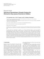
Figure 18: The epipolar geometry of two central catadioptric cameras with hyperbolic mirrors. (a) epipolar plane of two SVP ODVS, and
(b) epipolar plane with two epipolar lines.
(a)
O
A
θ
A
(b)
w
h
A
(c)
Figure 19: Epipolar geometry. (a) Imaging model. (b) The epipolar
lines for a pair of coaxial omnidirectional images are radial lines. (c)
When the images are projected onto a panorama, the epipolar lines
become parallel.
between the normal and the spindle Z is ε
1
. Due to these
relations, we can get
σ
= 180
◦
− ε,
2ε
= φ − θ
2
,
σ
1
= 180
◦
− ε
1
,
2ε
1
= θ
1
− θ
2
(7)
tan φ
=
t
1
F
1
(
t
1
− s
)
,tanθ
1
=
t
2
F
2
,tanθ
2
=
t
1
− t
2
F
2
− F
1
.
(8)
x
C
up
(φ
1
, β
1
)
φ
up-max
φ
up-90
φ
up-min
(a)
x
y
0
◦
180
◦
360
◦
C
up
(x
1
, y
1
)
Φ
up-max
Φ
up-90
Φ
up-min
(b)
Figure 20: Schematic diagram of panoramic vision photo graphed
by upper ODVS.
In (8), F1 is the firstly reflection mirror curve, F2is
the secondary reflection mirror curve. Using the triangular
relationship and simplifying (8), we can get
F
1
2
− 2αF
1
− 1 = 0,
(9)
F
2
2
− 2βF
2
− 1 = 0.
(10)
14 EURASIP Journal on Image and Video Processing
x
C
down
(φ
2
, β
2
)
φ
down-max
φ
down-90
φ
down-min
(a)
x
y
0
◦
180
◦
360
◦
C
down
(x
2
, y
2
)
Φ
down-max
Φ
down-90
Φ
down-min
(b)
Figure 21: Schematic diagram of panoramic vision photo graphed
by lower ODVS.
C
up
(x
1
,y
1
)
C
down
(x
2
,y
2
)
φ
up-max
φ
up-90
φ
up-min
φ
down-max
φ
down-90
φ
down-min
0
◦
180
◦
360
◦
Figure 22: Image point matching for two ODVS.
Among them,
α
=
(
F
1
− s
)(
F
2
− F
1
)
− t
1
(
t
1
− t
2
)
t
1
(
F
2
− F
1
)
−
(
t
1
− t
2
)(
F
1
− s
)
,
β
=
t
2
(
t
1
− t
2
)
+ F
2
(
F
2
− F
1
)
t
2
(
F
2
− F
1
)
− F
2
(
t
1
− t
2
)
.
(11)
Solutions of (9), (10)canbe
F
1
= α ±
α
2
+1,
(12)
F
2
= β ± β
β
2
+1.
(13)
Among them, F
1
is the differential of curve F
1
, F
2
is the
differential of curve F
2
.
In order to build some certain linear relationship
between a point on the image plane and the angle, it is
necessary to build a linear relationship between the distance
from the pixels P to the spindle Z and the angle, namely
φ
= a
0
· P + b
0
,
(14)
C(r, Φ, β, R, G, B, t)
Figure 23: Imaging point expression in Gaussian reference frame
coordinates.
Z
A
B
dc
Two t im es o f ma xi mu m
elevation (60
◦
)
C
X
F(t
1
):
F(t
2
):
s
F(t
1
):
F(t
2
):
s
Figure 24: The measurement principle of binocular omnistereo
vision sensor.
where a
0
, b
0
are arbitrary parameters.
Let f represent the focal length of the camera modules,
p represent the distance from the pixel point to the spindle
Z,and(t
2
, F
2
) represent the reflex points on the secondary
reflection mirror. According to imaging principle, we have
P
= f ·
t
2
F
2
.
(15)
From (8)and(9), we have
φ
= a
0
·
f ·
t
2
F
2
+ b
0
.
(16)
The mirror curve meeting (16) can meet the require-
ments of average angle resolution.
According to the principle of catadioptric, from (16), we
get
tan
−1
t
1
F
1
− s
=
a
0
·
f ·
t
2
F
2
+ b
0
.
(17)
From (9), (10), and (17), we get the digital solutions of
F
1
and F
2
through the four order Runge-Kutta algorithm
(as shown in Figure 10). Thus, the firstly reflecting mirror
and secondary folding mirror reflection obtained are of the
constant angle resolution.
EURASIP Journal on Image and Video Processing 15
(a) (b)
Figure 25: Panoramic images, detection of reliable line, and deviation compute of epipolar lines.
Figure 26: Unwrap omnidirectional image based on epipolar
match.
Figure 27: Imaging point matching for V-binocular ODVS using
SIFT algorithm.
3.4. Design of Constant Vertical Resolution Mirror. This
design constraint aims to achieve the goal that objects at a
(prespecified) fixed distance from the camera’s optical axis
will always be the same size in the image and independent
of its vertical coordinates. In other words, if we consider a
cylinder of radius, C, around the camera optical axis, we
want to ensure that ratios of distances (measured in the
vertical direction along the surface of the cylinder) remain
unchanged when measured in the image. Such invariance
should be obtained by adequately designing the mirror
profile—yielding a constant vertical resolution mirror.
As a practical example, this viewing geometry would
allow reading signs or text on the surfaces of objects
with minimal distortion. As another example, tracking is
facilitated by reducing the amount of distortion that an
image target undergoes when an object is moving in 3D.
Finally, in visual navigation it helps by providing a larger
degree of invariance of image landmarks with regard to the
viewing geometry.
Similar to the design of constant angular resolution
mirror, we can change constraints condition for (16)toget
constraints (18) in constant vertical resolution [29].
z
= a
0
·
f ·
t
2
F
2
+ b
0
.
(18)
Then, the first reflecting mirror and the second folding
mirror reflection are obtained for the constant vertical
resolution using the four order Runge-Kutta algorithm.
3.5. Fixed Single Viewpoint Camera Calibration. Another
important property of such designed mirrors is distance
sensitivity [25]. This value determines how the linear
projection properties degrade for objects laying at distinct
distances than those considered for the design. Since we
know the geometry of the catadioptric system, we can
compute the direction of light for each pixel passing through
the viewpoint. In this case, single effective viewpoint permits
the construction of geometrically correct panoramic images
as well as perspective [27].
A camera model can be built and calibrated if the mirror
surface is considered as a known revolution shape and is
modeled explicitly. For instance, the reflecting surface can
be a hyperboloidal placed in front of a common camera.
Another way of approaching camera calibration is assuming
that the pair camera-mirror possesses a SVP [25].
In order to satisfy the single viewpoint constraint, hyper-
boloidal omnistereo is composed of the hyperboloidal mirror
and the pinhole camera in the same vertical direction, and
the camera focus at the same position with hyperboloidal
mirror of the virtual focus C. So, the imaging process can be
divided into two steps: the conversion of mirror to the sensor
plane, and the conversion of sensor plane to the image plane,
as shown in Figure 12.
Every line passing through an optical center intersects
the image plane in one point, so we can represent rays of
the image as a set of unit vectors in R
3
such that one vector
corresponds just to one image of a scene point.
Let a scene point X
= [x, y, z]
T
be projected into u
in a sensor plane. Assume that the point u
= [u
, v
]
T
16 EURASIP Journal on Image and Video Processing
−120
−80
−40
0
40
80
120
Y (cm)
0 50 100 150 200 250
X (cm)
Face-to-face configuration
(a)
−400
−300
−200
−100
0
100
200
300
400
Y (cm)
0 200 400 600 800 1000
X (cm)
Face-to-face configuration
(b)
Figure 28: (a) Depth resolution for V-binocular ODVS with face-to-face configuration in 250 cm. (b) Depth resolution for V-binocular
ODVS with face-to-face configuration in 1100 cm.
−80
−40
0
40
80
Y (cm)
0 50 100 150 200 250
X (cm)
Back-to-back configuration
(a)
−400
−300
−200
−100
0
100
200
300
400
Y (cm)
0 200 400 600 800 1000
X (cm)
Back-to-Back configuration
(b)
Figure 29: (a) Depth resolution for V-binocular ODVS with back-to-back configuration in 250 cm. (b) Depth resolution for V-binocular
ODVS with back-to-back configuration in 1100 cm.
in the sensor plane (see Figure 12(a)) and a point u
=
[u
, v
]
T
in a digitized image (see Figure 12(b)) are related
by an affine transformation. Thus, u
= Au
+ t, where and
A
∈ R
2×2
, t ∈ R
2×1
. The complete image formation for
omnidirectional cameras can be written as
∃α>0:α
⎡
⎣
x
T
z
⎤
⎦
=
α
⎡
⎣
h
(
u
)
u
g
(
u
)
⎤
⎦
=
α
⎡
⎣
h
(
Au
+ t
)(
Au
+ t
)
g
(
Au
+ t
)
⎤
⎦
=
PX,
(19)
where matrix X is the homogeneous coordinate of the scene
point, X
= [x, y, z, l]
T
∈ R
4
,matrixP ∈ R
3×4
expresses
perspective projection of the scene X to its digitized image
u
. The nonlinear function g defined the geometrical shape of
mirror, and the nonlinear function h defined in the relation
of u
and h(u
)u
. u
is the distance of image point to
the center in sensor plane.
As the function g, h are the equation on the u
,
Scaramuzza et al. [30] made further analysis on perspective
projection model, and proposed using a function f
= g/h to
replace the function g, h. Then, (19) can be simplified
∃α>0:α
⎡
⎣
x
z
⎤
⎦
=
α
⎡
⎣
u
f
(
u
)
⎤
⎦
=
PX, (20)
where f is rotationally symmetric with respect to the sensor
axis, because both mirror profiles and pinhole camera are
manufactured with micrometric precision.
To take full advantage of this rotation symmetric, and
want this model to compensate for any misalignment
between the focus point of the mirror and the camera
optical center, Scaramuzza proposed the following Taylor
polynomial form for f
f
u
=
a
0
+ a
1
u
+ a
2
u
2
+ ···+ a
N
u
N
,
(21)
where the coefficients A, t, a
0
, a
1
, , a
N
and the polynomial
degree N are the model parameters to be determined by the
calibration. The specific methods of operation are given in
the literature [31].
Establishing a two-dimensional coordinate XoZ with the
focus point F,functionf
= g/hcan be described as the curve
in Figures 13 and 14 mapping the vertical distance of point
u
in the sensor plane, namely, the vertical distance of the
intersection point S
and effective viewpoint f . Here, the
point S
is intersection of the vertical line of point u
and
the incident light. The angle φ of incident light and the z-axis
holds
tan φ
=
u
f
(
u
)
=
u
a
0
+ a
1
u
+ a
2
u
2
+ ···+ a
N
u
N
.
(22)
EURASIP Journal on Image and Video Processing 17
−360
−320
−280
−240
−200
−160
−120
−80
−40
0
40
80
Y (cm)
0 50 100 150 200 250
X (cm)
Face-to-back configuration
(a)
−1200
−1000
−800
−600
−400
−200
0
200
400
Y (cm)
0 200 400 600 800 1000
X (cm)
Face-to-back configuration
(b)
Figure 30: (a) Depth resolution for V-binocular ODVS with face-to-back configuration in 250 cm. (b) Depth resolution for V-binocular
ODVS with face-to-back configuration in 1100 cm.
V-binocular
stereo ODVS
Object
Distance between view
point and object
Figure 31: Experiments for measuring depth of object.
Equations (20)and(22) capture the relationship between
the point u
in the digitized image and the vector P
emanating from the optical center to a scene point X.
4. Design of Vertically Aligned Binocular
Omnistereo Vision Sensor
There are some omnistereo sensors and systems. Some of
the drawbacks in other omnistereo can be overcome by a
vertically aligned binocular omnistereo configuration (Fig-
ures 15, 16,and17). The depth equation of the V-binocular
stereo is simply the same as a traditional perspective stereo.
Previously work in V-binocular omnistereo includes the
approaches using two optical omnidirectional sensors [24,
28] and using a pair of 1D scanning cameras [32]. In the later
approach, high-resolution stereo pair is captured by a pair
of vertically aligned 1D scan cameras. Because of the simple
epipolar geometry, the depth map could be recovered during
rotation in the scanning approach. Although the scanning
approach cannot be applied in dynamic scenes, it is a simple
and practical solution for modeling static scenes in high
resolution.
4.1. Vertically Aligned Binocular Omnistereo Vision Sensor
with Face-to-Face Configuration. Figure 15 shows Design
drawing, Real product image, Vertically-aligned binocular
omnistereo model in cylindrical surface and FOV of various
vertically aligned binocular omnistereo vision sensor by face-
to-face configuration. The diagonal part of the Figure 15(d)
is the range of binocular stereo vision.
The face-to-face configuration with a larger range of
binocular stereo range is more suitable to the mathematic
geometric calculations in the cylindrical coordinate system.
Furthermore, it can implement a longer baseline distance.
Constant vertical resolution mirror is more appropriate for
this configuration.
4.2. Vertically Aligned Binocular Omnistereo Vision Sensor
w ith Back-to-Back Configuration. Figure 16 shows design
drawing, real product image, vertically aligned binocular
omnistereo model in cylindrical surface, and FOV of var-
ious vertically aligned binocular omnistereo vision sensor
by back-to-back configuration. The diagonal part of the
Figure 16(d) is the range of binocular stereo vision.
The face-to-face configuration with a smaller range of
binocular stereo can be captured in 360
◦
× 360
◦
global sur-
face real-time video images and is suitable to the mathematic
geometric calculations in spherical coordinate system. It has
a shorter baseline distance, and is easy to be miniaturized due
to its compact structure. The mirror designed with average
angleresolutionismoreappropriateforthisconfiguration.
4.3. Vertically Aligned Binocular Omnistereo Vision Sensor
w ith Face-to-Back Configuration. Figure 17 shows Design
drawing, Real product image, vertically aligned binocular
omnistereo model in orthogonal coordinates, and FOV of
various vertically aligned binocular omnistereo vision sensor
by face-to-back configuration. The diagonal part of the
Figure 17(d) is the range of binocular stereo vision. The
range of face-to-back configuration of binocular stereo is
isotropic.
As the catadioptric images are in the same direction,
it may be better that hyperbolic mirrors are selected for
binocular stereo catadioptric mirrors. It is more suitable
for the camera measurement and the mathematic geometric
calculations in the rectangular plane system. Baseline length
is shorter than that of Figure 15 case, but longer than that of
Figure 16 case.
18 EURASIP Journal on Image and Video Processing
(a) Sphere
panoramic image
(617, 66)
(617, 129)
(b) Unwrapped panoramic image (depth = 100 cm)
(617, 70)
(617, 126)
(c) Depth =
200 cm
(617, 71)
(617, 123)
(d) Depth =
300 cm
(617, 72)
(617, 120)
(e) Depth =
400 cm
(617, 73)
(617, 118)
(f) Depth =
500 cm
Figure 32: Experiments for matching the object point and measuring the depth of object point.
−10
−5
0
5
10
15
20
25
30
35
40
Error rate (%)
30 50 70 90 110 130 150 170 190 210 230 250
Distance (cm)
Back-to-back configuration
Face-to-back configuration
Face-to-face configuration
Figure 33: Depth error rate of viewing object from 30cm to 250 cm
for there V-binocular ODVS configuration.
4.4. Epipolar Geometry. Epipolar geometry describes a geo-
metric relationship between the positions of the correspond-
ing points in two images acquired by central cameras [33].
Since the epipolar geometry is a property of central projec-
tion cameras, it also exists for central catadioptric cameras,
for example, back-to-back configuration, see Figure 18.
(1) In Figure 18, G(X, Y, Z) is an object point of three-
dimensional space. Point O
m1
,O
m2
is the focus of
hyperbolic mirror. I
1
,I
2
is CCD imaging plane. C
1
,C
2
is the center point of image plane. P
1
, P
2
is the image
point of object point G. L
1
is the line through point
C
1
and P
1
,andL
2
is the line through point C
2
and P
2
.
−50
0
50
100
150
200
Error rate (%)
100 200 300 400 500 600 700 800 900 1000 1100
Distance (cm)
Back-to-back configuration
Face-to-back configuration
Face-to-face configuration
Figure 34: Depth error rate of viewing object from 100 cm to
1100 cm for there V-binocular ODVS configuration.
(2) From the Figure 18, we can see that point P
1
and P
2
is
a pair of imaging points about object point G. As the
points C
1
,C
2
,P
1
, P
2
are in the epipolar plane specified
by points G, O
m1
and O
m2
, and plane I
1
parallel to the
plane I
2
, then points P
1
and P
2
must be located on the
line L
1
and L
2
,respectively.
(3) that is, point P
1
’s match point, P
2
,mustbelocatedon
P
1
’s epipolar line L
2
, and point P
2
’s match point, P
1
,
must be located on P
2
’s epipolar line L
1
.
EURASIP Journal on Image and Video Processing 19
In stereo vision, the epipolar constraint is an important
part (as described above). This constraint reduces the
problem of finding corresponding points to a 1-D search.
The epipolar constraint for catadioptric systems has been
studied by [Nene and Nayar, 1998] and [10]. For hyperbolic
mirror, the epipolar lines are radial lines, and corresponding
points must lie on its epipolar.
Once the image of the hyperboloid is projected onto
a cylinder (panoramic image), the epipolar lines become
parallel. Moreover, if each image in the stereo pair is
projected onto a cylinder of the same size, the epipolar lines
will match up.
5. Unwrap Omnidirectional Image, Match
Feature Points, and Calculate Spatial
Information
5.1. Unwrap Omnidirectional Image. Omnidirectional image
unwrap algorithm unwraps all omnidirectional images from
ODVS. As shown in Figure 19, x-axis of image expresses
azimuth angle, y-axis expresses incidence angle in this paper.
We need to separate image of central part from omni-
directional image. After that, omnidirectional image is
unwrapped: the calculated step at horizontal direction in
the unwrap algorithm is Δβ
= 2π/l; the calculated step
at vertical direction in the unwrap algorithm is Δm
=
(φ
max
− φ
min
)/m; in the equation, φ
max
is the scene lighting
angle corresponding the biggest effective radius (Rmax) of
the panorama relevant, and φ
min
is the scene lighting angle
corresponding the smallest effective radius (Rmin) of the
panorama relevantly. Refer to Pot
´
u
ˇ
cek [26] for details on
omnidirectional image unwrap algorithm.
The coordinate of C corresponding the original point
C(φ, β) represented by polar coordinates is
x
=
β
Δβ
,
y
=
φ − φ
min
Δm
.
(23)
In (23), Δβ is the calculated step in the horizontal
direction, β is azimuth angle, Δm is the calculated step in the
vertical direction, φ is the scene lighting angle corresponding
the effective radius R of the panorama relevant, and φ
min
is
the scene lighting angle corresponding the smallest effective
radius (Rmin) of the panorama relevantly.
5.2. Match of Image Point. Figure 20 shows unfolded image
of SVP ODVS. In unfolded image, x-axis expresses azimuth
angle, and y-axis expresses incidence angle. The principle of
splicing is to match the azimuth angle of two SVP ODVS,
which makes the same object from two unfolded image to
be on the same vertical line in splicing image. If it justifies
the longitude of the two SVP ODVS when designing, it
realizes the condition of bound by a line in the structure.
After meeting the condition of bound by a line in the
structure, the problem of searching corresponding points
from the entire plane is transformed into the problem of
searching corresponding points in a vertical line, which
provides foundation for the rapid match between point-to-
point. From the point of view of latitude, if there are certain
linear relation between the incidence angle and the pixels
on image plane of the SVP ODVS designed, the incidence
angle of the two SVP ODVS combined can be calculated
conveniently, and also we can simplify the problem of
searching corresponding points in a vertical line to that in a
certain area of the vertical line. As shown in (24), (e.g., back-
to-back configuration)
180
◦
≤ φ
1
+ φ
2
≤ 2φ
max
.
(24)
In the equation, φ
1
is the incident angle of ODVS’s
imaging point which is underneath, φ
2
is the incident angle
of ODVS’s imaging point which is aloft, and φ
max
is the
maximum of ODVS imaging point called elevation.
We mark the ODVS aloft as ODVSup and the ODVS
underneath as ODVSdown. Assume that the object point C is
in the range of the binocular vision. Its imaging point in the
panorama relevant of ODVSdown is C
up
(φ
1
, β
1
) (shown in
Figure 20(a)), and its object point in the spherical launched
plans is C
up
(x
1
, y
1
) (shown in Figure 20(b)). In the figure,
φ
up-max
shows the elevation when the incidence angle of
ODVSup is biggest, φ
down−90
shows the value when the
incidence angle of ODVSup is 90
◦
,andΦ
up-min
shows the
depression angle when the incidence angle of ODVSup is the
smallest.
We can also know that object point C’s imaging point
in the panorama relevant of ODVSdown is C
down
(φ
2
, β
2
)
(shown in Figure 21(a)), and its object point in the spherical
launched plans is C
down
(x
2
, y
2
) (shown in Figure 21(b)).
The incidence angle bigger than 90
◦
is called elevation
angle, while the one smaller than 90
◦
is called depression
angle. In this paper, set the incidence angle of the ODVS
as elevation, so it must have some area that both of two
ODVSs can reach, and that is named binocular vision scope.
For the same object point in the space, if it can be seen in
the binocular vision scope, it must have two image points
C
up
(φ
1
, β
1
)andC
down
(φ
2
, β
2
) in the panorama relevant of
the two ODVS which have the same azimuth angle β, that
is, β
1
= β
2
.
As a result, the X coordinate corresponding to the
spherical launched plans is same too, that is, x
1
= x
2
.So
according to this principle, we can justify the azimuth angle
in the spherical launched plans of two ODVS, as shown in
Figure 22.Actually,Figure 22 is the mixture of Figures 20(b)
and 21(b), which can realize the justifying of the azimuth
angle in the spherical launched plans conveniently.
5.3. The Coordinate of Gaussian Sphere and Central Eye.
Human-centered stereo omnidirectional vision has high
third dimension and fidelity. We call the center of binocular
vision’s baseline central eye which is used to describe the
information of object point C(r, Φ,β, R, G, B, t)inspace.The
meaning of each physical parameter is shown in Figure 23.
Equation (25) can be used to represent any object point
in space
c
= C
r, Φ, β, R, G, B, t
.
(25)
20 EURASIP Journal on Image and Video Processing
We adopt a scientific and uniform Gaussian sphere
coordinate in binocular stereo vision to express all object
point by using seven physical parameters. It can lay a good
technology foundation for model simplification and fast
calculation later. It also provides convenience for the follow-
up geometric calculation.
5.4. Object Point’s Spatial Information and Color Information
Acquisition and Calculation. The spatial information of
object point is expressed by three parameters r, Φ,andβ
in Gaussian sphere coordinate. Because we use central eye as
the origin of Gaussian sphere coordinate, the calculation of
spatial information turns into the calculation of the position
relation between object point and central eye. Among them,
r expresses the distance between origin O and object point.
Compared to central eye, object point’s longitude value is
Φ and object point’s latitude value is β. According to the
principle of binocular vision, we can estimate the object
point’s depth information, as shown in Figure 9.
According to the imaging principle of binocular vision,
we can get the distance between object point and viewpoint
that is depth of field only if we obtain the incidence angle of
object point at two ODVSs φ
1
and φ
2
. Because two ODVSs
are composed with Back-to-Back configuration, φ
1
and φ
2
can be calculated by
φ
1
= φ
min
+
φ
max
− φ
min
m ·
m − y
1
,
φ
2
= φ
min
+
φ
max
− φ
min
m · y
2
.
(26)
In the equation, m is the height of unwrapped image.
y
1
, y
2
is match point’s y-axis in two unwrapped images.
φ
min
is the minimum incidence angle. φ
max
is the maximum
incidence angle.
According to the triangular relationship, we can get the
distance r between origin O and object point C
r
= OC =
AC
2
+
dc
2
2
−2AC
dc
2
cos A
=
dc
sin
(
B + A
)
· sin B
2
+
dc
2
2
−
dc
2
sin
(
B + A
)
·sin B cos A
=
dc
sin
φ
1
+ φ
2
·
sin φ
1
2
+
dc
2
2
−
dc
2
sin
φ
1
+ φ
2
·
A,
(27)
where A denotes sin φ
1
cos φ
2
.
In the equation, ∠A
= 180−φ
2
,∠B = 180−φ
1
,anddc is
the distance between ODVSup’s viewpoint and ODVSdown’s
viewpoint.
The angle Φ can be calculated by (28):
Φ
= arcsin
dc
2r
sin φ
2
+ φ
2
− 180
◦
.
(28)
Φ is the incidence angle of object point; dc is the distance
between point A and point B in binocular system; r is the
distance between feature point and central eye; φ
2
is the
incidence angle of ODVSup.
Another parameter of object point β can choose any one
from two ODVS’s azimuth angle. t is the time from computer
system.
The average value of each color components R, G,andB
from matching points of two unwrapped images is adopted
in the calculation of color information as central eye’s color-
coding. First, we obtain color components R
ODVS1
, R
ODVS2
,
G
ODVS1
, G
ODVS2
, B
ODVS1
,and B
ODVS2
and from matching
points of two unwrapped images, then calculate the average
value of each color components as central eye’s color coding.
The equation is shown as follows:
R
=
R
ODVS1
+ R
ODVS2
2
,
G
=
G
ODVS1
+ G
ODVS2
2
,
B
=
B
ODVS1
+ B
ODVS2
2
.
(29)
In the equation, R is the average value of red component,
R
ODVS1
is red component of ODVS one, R
ODVS2
is red
component of ODVS two. G is the average value of green
component, G
ODVS1
is green component of ODVS one,
G
ODVS2
is green component of ODVS two. B is the average
value of blue component, B
ODVS1
is green component of
ODVS one, B
ODVS2
is blue component of ODVS two. The
value range of them are 0
∼255.
5.5. Depth Accuracy. The vertically aligned binocular omnis-
tereo systems have two viewpoints and fixed baseline. For
the stereo matching between the two converted panoramic
views, any conventional algorithms are applicable. Once
correspondence between image points is established, depth
computation in both spherical and cylindrical panorama is
straightforward by simple triangulation in (27). In addition,
the depth resolution mainly depends on camera resolution,
the length of baseline and binocular omnistereo vision sensor
configuration
∂r
= f
r
2
dc
∂φ, (30)
where r is the distance between viewing object and binocular
omnistereo vision sensor, dc is the length of baseline, and
∂φ is similar to the camera resolution. It seems that larger
baseline and higher camera resolution will get better depth
accuracy. Therefore, depth estimation error is proportional
to the square of the distance between viewing object and
binocular omnistereo vision sensor. The depth accuracy of
the V-binocular omnistereo is isotropic in all directions, and
the epipolar lines are simply vertical lines in omnidirectional
image. More detail of the depth resolution and error analysis
can be found in references [34, 35].
EURASIP Journal on Image and Video Processing 21
6. Experiment Results
According to the above idea, we have developed three V-
binocular stereo ODVS types as shown in Figures 15(b),
16(b),and17(b). The video information obtained from
binocular stereo ODVSs are transmitted through two USB
interfaces to computer, which processes the image and
matches the object point, and calculates the distance of object
point. Figure 25 shows the panoramic images obtained
by V-binocular omnidirectional vision sensor shown in
Figure 15(b), where image resolution is 640
× 480 pixels.
6.1. Epipolar Plane with Two Epipolar Lines. In order to verify
the good characteristic on 3D matching of the device, in
this paper, we use SIFT (scale-invariant feature transform)
feature matching algorithm [36] to match the feature points
for Figure 26 and obtain the results shown in Figure 27,
in which all the connections of the matching points are
almost parallel. In other words, it is feasible to match the
feature points got from the unwrap image on the line of
the connections, and, after fixing the device, use binocular
ODVS to demarcate processing. Then, we can get the
position of these matched line and only need to find match
points on the matched line in later matching processes, which
greatly reduces the complexity of the matching.
6.2. Match of Image Point. The two sensor planes formed by
vertically aligned binocular omnistereo vision sensor exist
a parallel error and a coaxial error, which are shown in
Figure 27. Actually, match lines of all image points is not
always in verticality. In other words, the same image point
in the two image planes may be not in the same epipolar
plane, in despite of unwrap omnidirectional image based on
epipolar match, shown as Figure 26. To decrease matching
error, we use normalized cross-correlation arithmetic to
match feature points from up and down panoramic images,
based on feature point which has same brightness in
neighbor window area, shown as
Corr
=
N/2
j
=−N/2
M/2
i
=−M/2
[
r,g,b
]
{
(
A
)
·
(
B
)
}
N/2
j
=−N/2
M/2
i
=−M/2
[
r,g,b
]
(
A
)
2
·
N/2
j
=−N/2
M/2
i
=−M/2
[
r,g,b
]
(
B
)
2
,
A
= C
down
x
2
+i, y
2
+ j
−
C
down
r, g,b
,
B
= C
up
x
1
+ i, y
1
+ j
− C
up
r, g,b
,
(31)
where N and M are the size of the neighbor window area.
C
up
(x
1
, y
1
) is the brightness of feature point I
r
(x
1
, y
1
)inup
panoramic image. C
down
(x
2
, y
2
) is the brightness of searching
feature point in down panoramic image, shown as Figure 22
C
down
r, g,b
=
N/2
j=−N/2
M/2
i=−M/2
C
down
r, g,b
x
2
+ i, y
2
+ j
,
C
up
r, g,b
=
N/2
j=−N/2
M/2
i=−M/2
C
up
r, g,b
x
1
+ i, y
1
+ j
.
(32)
If the Corr of feature point I
s
(x
2
, y
2
)calculatedby(28)
is higher than threshold of normalized cross-correlation,
this point can be the search matching feature point. In this
paper, we adopt the feature point I
r
(x
1
, y
1
) in up panoramic
image to search the cross-correlation feature point I
s
(x
2
, y
2
)
in down panoramic image. As matching feature point must
be near to its epipolar plane, the value of N is used to 6
pixels, and the value of M is determined by the image range
of binocular omnistereo vision.
6.3. Measuring Dep th of Viewing Object. Once the corre-
spondence between image points has been established, depth
measurement in cylindrical panorama is straightforward by
simple triangulation (27)and(28). Figures 28, 29,and
30 show a sampling of depth resolution in three kinds
of FOV of Binocular Omnistereo Vision. The sampling is
obtained by computing depth for every possible pair of image
correspondences.
In there figure, each point represents the estimated
position calculated by all the possible pair of image cor-
respondence in a single epipolar plane, the coordinate (0,
0) expresses the position of “central eye”. These instances
are generated with the three configurations of V-binocular
ODVS, and the parameters of each are given in above.
In order to get better depth accuracy range for special
application requirements, we carry out experiments for
measuring depth of viewing object using three V-binocular
stereo ODVS types, that is, back-to-back configuration, face-
to-face configuration, and face-to-back configuration. One
of the experiment devices is shown in Figure 31 (e.g., back-
to-back configuration).
The panoramic images obtained from binocular stereo
ODVS are transmited to computer through two USBs. Then,
the computer processes the images, matches the object point,
and measures the depth of object point. Figure 32 is the
panoramic image of both the above frame and the below
frame graphed by V-binocular stereo ODVS with back-
to-back configuration, in which sphere panoramic image
resolution is 640
∗ 480 pixels and unwrapped panoramic
image resolution is 1280
∗ 200 pixels. The experiments of
measuring depth between viewing object (in red cross mark)
and central eye (origin O) carried out by using the binocular
stereo ODVS experiment device, from short distance to long
distance, respectively. Figure 31 shows parts of experiments
for matching the object point and measuring the depth of
object point. The software is developed by Java and runs on
Windows XP.
22 EURASIP Journal on Image and Video Processing
Experiment results of measuring depth between view
point and object from 30 cm to 250 cm and 100 cm to
1100 cm are presented in Tables 2 and 3,respectively,which
uses V-binocular ODVS with face-to-face configuration
and chooses baseline length in Figure 15(b) as 40.58 cm.
Experiment resluts of measuring depth between view point
and object from 30 cm to 250 cm and 100 cm to 1100 cm
are presented in Tables 4 and 5, respectively, which uses
V-binocular ODVS with back-to-back configuration and
chooses baseline length in Figure 16(b) as 9.80 cm. And
experiment resluts of measuring depth between view point
and object from 30 cm to 250 cm and 100 cm to 1100 cm
are presented in Tables 6 and 7, respectively, which uses
V-binocular ODVS with face-to-back configuration and
chooses baseline length in Figure 17(b) as 18.70 cm.
The depth errors of viewing object from 30 cm to 250 cm
and 100 cm to 1100 cm for V-binocular ODVS with face-
to-face, back-to-back, and face-to-back configuration are
shown in Figures 33 and 34, respectively. These results
indicate that the measured value of short distance measuring
is close to the actual value. This is because the closer
to the center of stereo ODVS, the more accurate of the
measuring point’s incidence angle. From these figures, noting
V-binocular ODVS with face-to-face configuration has the
longest baseline length, we are aware that this configuration
can get high depth measuring accuracy. In addition, the
farther the target object is, the larger the baseline should be.
Now, we move on to analyze errors. According to the
principle of binocular stereo vision, the position of object
can be measured exactly. But the image is not continuous
when it is obtained by imaging unit; that is, the image is
discrete data which takes pixel as a unit. There is minimum
resolution ratio error in measurement, because of the
camera’s resolution. This problem can be alleviated by using
high resolution camera.
According to results of measurement, depth-estimation
error will increase with the measuring distance enlarge.
The reason is that, when measuring distance increases, the
measuring point’s incidence angle on two ODVS, that is, φ
1
and φ
2
, becomes small and tends to 90
◦
, which makes the
distance from target object r of (30) very sensitive to the
change of incidence angle.
7. Conclusion
In this paper, a novel dynamic omnistereo approach is pre-
sented, in which viewpoints of two omnidirectional cameras
can form the optimal stereo configuration for localizing
moving objects. Further extension is made to the concept
of omnidirectional imaging from viewer-centered to object
centered representation, thus allowing building omnidirec-
tional models of large objects or even our planet. Numerical
analysis is conducted on omnidirectional representation,
epipolar geometry, and depth error character, which helps
for the research and applications of omnidirectional stereo
vision.
In the study, we conduct comparative evaluation of
ODVS which are classified according to five criteria: the
cabrication technology, the resolution, the SVP property, the
VFOV property, and isotropy. Each category is explained
and accompanied with several examples of real ODVSs
with detailed descriptions. Besides, comparative evaluation
of Binocular Omnistereo Vision Sensor (BOSVS) is also
presented, which are classified according to five criterias:
FOV of the BOSVSs, epipolar geometry, matching the image
point, depth accuracy, and coordinate system for each type
of BOSVSs in 3D calculations. The classification parameters
and details of each type of ODVSs and BOSVSs bring
valuable guidelines for the choice of ODVS or BOSVS
depending on the application requirements.
Stereovision has always been an important issue of
computer vision and video measurement, the benefits of
the binocular omnistereo vision sensor-based stereovision
measurement device developed by this work are mainly
manifested in the following.
(1) Capturing the 360
◦
∗ 360
◦
omnidirectional 3D
video images in real time and getting the panoramic
images of the entire monitoring sphere through geo-
metric calculation. Additionally, the tracked moni-
toring objects will not disappear from the camera.
(2) Designing the ODVS with constant angular reso-
lution, constant vertical resolution and hyperbolic
type, which can get images with no distortion
and thus helps to solve the problems existing in
catadioptric ODVS. Providing a complete theoretical
system and model for the realization of real time
tracking of fast-moving targets in large space.
(3) Proposing a new omnidirectional binocular vision.
In the overlapping vision region of the two ODVS,
binocular omnistereo vision sensor has the real-time
perceiving, fusion faculty, and stereo feeling.
(4) Each ODVS with SVP constituting the binocular
omnistereo vision sensor is designed with constant
angular resolution, constant vertical resolution, and
hyperbolic type, and both of the cameras employ
the same criteria, which makes our device capable
of achieving truly symmetry and capturing real
time video image under the spherical coordinates,
cylindrical coordinates, and orthogonal coordinates,
respectively. As a result, we can realize point-to-point
match rapidly, which gives a great convenience for the
following 3D image processing.
(5) The complicated calibration work is no longer
needed. Feature extraction is very convenient, and
rapid 3D image matching can be achieved.
(6) There is no fixed focal length problem any more, as
ODVS is developed with catadioptric technology: the
image clarity is the same in any region.
(7) Double catadioptric imaging technology is employed
which makes the implementation of small or echo
micro device easier.
(8) Adopts a kind of uniform coordinates at the image
gathering, 3D matching, 3D image reconstruction,
and 3D objects measuring are much easier. The
EURASIP Journal on Image and Video Processing 23
device designed and developed can be widely used in
industrial inspection, military reconnaissance, geo-
graphical surveying, medical cosmetic surgery, bone
orthopedics, cultural reproduction, criminal evi-
dence, security identification, air navigation, robot
vision, mold rapid prototyping, virtual reality, ani-
mated films, games, and other application areas.
In the near future, we will investigate active omnistereo
image by using stereo structure light produced by LED (Light
Emitting Diode) or laser radiation device.
Acknowledgments
This project is supported by National Natural Science
Foundation of China under Grant no. 61070134, 60873228
and by Key Science and Technology Project of Zhejiang
Province of China under Grant no. 2009C14033.
References
[1] S. Baker and S. K. Nayar, “A theory of catadioptric image
formation,” in Proceedings of the IEEE 6th International
Conference on Computer Vision (ICCV ’98), pp. 35–42, January
1998.
[2]J.S.ChahlandM.V.Srinivasan,“Reflectivesurfacesfor
panoramic imaging,” Applied Optics, vol. 36, no. 31, pp. 8275–
8285, 1997.
[3] T. L. Conroy and J. B. Moore, “Resolution invariant surfaces
for panoramic vision systems,” in Proceedings of the IEEE 7th
International Conference on Computer Vision (ICCV ’99),pp.
392–397, September 1999.
[4] C. Decc
´
o, J. Gaspar, N. Winters, and J. Santos-Victor,
“Omniviews mirror design and software tools,” Tech. Rep.,
Omniviews deliverable DI-3, September 2001,
.ist.utl.pt/labs/vislab/.
[5] J. Gaspar, N. Winters, and J. Santos-Victor, “Vision-based nav-
igation and environmental representations with an omnidi-
rectional camera,” IEEE Transactions on Robotics and Automa-
tion, vol. 16, no. 6, pp. 890–898, 2000.
[6] C. Geyer and K. Daniilidis, “A unifying theory for central
panoramic systems and practical applications,” in Proceedings
of the European Conference on Computer Vision (ECCV ’00),
vol. 2, pp. 445–461, June 2000.
[7] R. A. Hicks and R. Bajcsy, “Catadioptric sensors that approxi-
mate wide-angle perspective projections,” in Proceedings of the
IEEE Workshop on Omnidirectional Vision (OMNIVIS ’00), vol.
1, pp. 97–103, June 2000.
[8] F. Marchese and D. Sorrenti, “Omni-directional vision with
a multi-part mirror,” in Proceedings of the 4th International
Workshop on Robocup, pp. 289–298, 2000.
[9] S. K. Nayar, “Catadioptric omnidirectional camera,” in Pro-
ceedings of the IEEE Computer Society Conference on Computer
Vision and Pattern Recognition (CVPR ’97), pp. 482–488, San
Juan, Puerto Rico, USA, June 1997.
[10] T. Svoboda, T. Pajdla, and V. Hlav
´
ac, “Epipolar geometry for
panoramic cameras,” in Proceedings of the European Conference
on Computer Vision (ECCV ’98), pp. 218–231, Freiburg,
Germany, July 1998.
[11] K. Yamazawa, Y. Yagi, and M. Yachida, “Obstacle detection
with omnidirectional image sensor HyperOmni vision,” in
Proceedings of the IEEE International Conference on Robotics
and Automation (ICRA ’95), pp. 1062–1067, May 1995.
[12] B. Mi
ˇ
cu
ˇ
s
´
ık and T. Pajdla, “Autocalibration & 3D reconstruc-
tion with non-central catadioptric cameras,” in Proceedings of
the IEEE Computer Society Conference on Computer Vision and
Pattern Recognition (CVPR ’04), vol. 1, pp. 58–65, July 2004.
[13] P. Doubek and T. Svoboda, “Reliable 3D reconstruction from a
few catadioptric images,” in Proceedings of the IEEE Workshop
on Omnidirectional Vision (OMNIVIS ’02), pp. 71–78, 2002.
[14] P. Sturm, “A method for 3D reconstruction of piecewise planar
objects from single panoramic images,” in Proceedings of the
24 EURASIP Journal on Image and Video Processing
IEEE Workshop on Omnidirectional Vision (OMNIVIS ’00),pp.
119–126, 2000.
[15] G B. Kim and S C. Chung, “An accurate and robust stereo
matching algorithm with variable windows for 3D measure-
ments,” Mechatronics, vol. 14, no. 6, pp. 715–735, 2004.
[16] Q. Yang et al., “3D visual new method based on the edge of the
match,” Instrumentation Journal, vol. 22, no. 3, pp. 255–256,
2001.
[17] Z. Xunjie and L. Chengjin, “The key technology of real-time
distance measurement by using binocular stereo system,” Laser
and Infrared, vol. 36, no. 9, pp. 874–877, 2006.
[18] S. You et al., “Stereo vision research and progress,” Chinese
Journal of Graphic Images, vol. 2, no. 1, pp. 17–23, 1997.
[19] Y P. Tang, Y J. Ye, Y H. Zhu, and X K. Gu, “Research on
intelligent omni-directional vision sensors and their applica-
tions,” Chinese Journal of Sensors and Actuators, vol. 20, no. 6,
pp. 1316–1320, 2007.
[20] F. Zhou et al., “Field calibration technology based on binoc-
ular visual sensor,” Instrumentation Journal,vol.21,no.2,pp.
1316–1320, 2000.
[21] Q. Mao-lin, “Camera calibration summary in computer
visual,” Journal of Automation, vol. 26, no. 1, pp. 43–55, 2000.
[22] H. Hirschm
¨
uller, P. R. Innocent, and J. Garibaldi, “Real-time
correlation-based stereo vision with reduced border errors,”
International Journal of Computer Vision, vol. 47, no. 1–3, pp.
229–246, 2002.
[23] Y. Tang, “Omni directional vision sensors without dead angle,”
Chinese Patent no. 200710066757.0, 2007.
[24] J. Gluckman, S. K. Nayar, and K. Thorek, “Real-time omni-
directional and panoramic stereo,” in Proceedings of DARPA
Image Understanding Workshop, pp. 299–303, November 1998.
[25] R. Orghidan, Catadioptric Stereo Based on Structured Light
Projection, Universitat de Girona, Catalonia, Spain, 2005.
[26] I. Pot
´
u
ˇ
cek, Omnidirectional Image Processing for Human
Detection and Tracking, Brno University of Technology, 2006.
[27] S. Barker and S. K. Nayar, “Single viewpoint catadioptric cam-
eras,” in Panoramic Imaging: Sensors, Theory, and Application,
R. Benosman and S. B. Kang, Eds., 2001.
[28] B. Mi
ˇ
cu
ˇ
sik and T. Pajdla, “Estimation of omnidirectional
camera model from epipolar geometry,” in Proceedings of the
IEEE Computer Society Conference on Computer Vision and
Pattern Recognition (CVPR ’03), pp. 485–490, June 2003.
[29] J. Gaspar, C. Decc
´
o, J. Okamoto Jr., and J. Santos, “Con-
stant resolution omnidirectional cameras,” in Proceedings
of Workshop on Omni-Directional Vision (OMNIVIS ’02),
Copenhagen, Denmark, June 2002.
[30] D. Scaramuzza, A. Martinelli, and Siegwart, “A toolbox for
easy calibrating omnidirectional camera,” in Proceeding of
the IEEE International Conference on Intelligent Robots and
Systems, pp. 27–34, Beijing, China, 2006.
[31] D. Scaramuzza, “Omnidirectional camera and calibration
toolbox for matlab,” March 2009, Google for “OCAMCALIB”.
[32] K. G. Konolige and R. C. Bolles, “Extra set of eyes,” in
Proceedings of DARPA Image Understanding Workshop, vol. 1,
pp. 25–32, 1998.
[33] T. Svoboda and T. Pajdla, “Epipolar geometry for central cata-
dioptric cameras,” International Journal of Computer Vision,
vol. 49, no. 1, pp. 23–37, 2002.
[34] Z. Zhu, “Omnidirectional stereo vision,” in
Proceedings of the
10th IEEE Workshop on Omnidirectional Vision (ICAR ’01),pp.
22–25, Budapest, Hungary, August 2001.
[35] G. Jang, S. Kim, and I. Kweon, “Single camera catadioptric
stereo system,” in Proceedings of the 6th Workshop on Omnidi-
rectional Vision, Camera Ne tworks and Non-Classical Cameras
(OMNIVIS/ICCV ’05), Beijing, China, October 2005.
[36] Y. Ke and R. Sukthankar, “PCA-SIFT: a more distinctive
representation for local image descriptors,” in Proceedings of
the IEEE Computer Society Conference on Computer Vision and
Pattern Recognition (CVPR ’04), vol. 2, pp. 506–513, July 2004.