Báo cáo hóa học: " Research Article A Dynamic Tap Allocation for Concurrent CMA-DD Equalizers" pot
Bạn đang xem bản rút gọn của tài liệu. Xem và tải ngay bản đầy đủ của tài liệu tại đây (1.43 MB, 6 trang )
Hindawi Publishing Corporation
EURASIP Journal on Advances in Signal Pr ocessing
Volume 2010, Article ID 278686, 6 pages
doi:10.1155/2010/278686
Research Ar ticle
A Dynamic Tap Allocation for Concurrent CMA-DD Equalizers
Diego von B. M. Trindade, Vitor Halmenschlager, Leonardo Ortolan, Maria C. F. De Castro,
Fernando C. C. De Castro, and Fabr
´
ıcio Ourique
Centro de Pesquisa em Tecnologias Wireless (CPTW), Pontif´ıcia Universidade Cat´olica do Rio Grande do Sul (PUCRS), Avenda
Ipiranga 6681, 90619-000 Porto Alegre, RS, Brazil
Correspondence should be addressed to Fabr
´
ıcio Ourique,
Received 10 August 2010; Revised 23 September 2010; Accepted 20 October 2010
Academic Editor: Christoph F. Mecklenbr
¨
auker
Copyright © 2010 Diego von B. M. Trindade et al. This is an open access article distributed under the Creative Commons
Attribution License, which permits unrestricted use, distribution, and reproduction in any medium, provided the original work is
properly cited.
This paper proposes a dynamic tap allocation for the concurrent CMA-DD equalizer as a low complexity s olution for the blind
channel deconvolution problem. The number of taps is a crucial factor which affects the performance and the complexity of
most adaptive equalizers. Generally an equalizer requires a large number of taps in order to cope with long delays in the channel
multipath profile. Simulationsshow that the proposed new blind equalizer is able to solve the blind channel deconvolution problem
with a specified and reduced number of active taps. As a result, it minimizes the output exc e ss mean square error due to inactive
taps during and after the equalizer convergence and the hardware complexity as well.
1. Introduction
The Concurrent Equalizer (CEQ) is based on a concurrent
architecture which comprises the classical direct decision
(DD) equalizer and Godard’s widespread known constant
modulus (CMA) blind equalizer [1]. In the C EQ architec-
ture, the DD branch is coordinated b y the CMA branch
gradient trajector y. Since the C EQ proposition in 2001 [2],
several contributions have been reported [3–5], to name a
few. A significant complexity reduction is achieved when
both the DD-updated filter and the CMA-updated filter are
replaced by one single equivalent FIR filter located after
the sum block in the original concurrent split architecture,
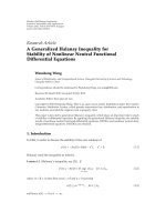
as shown in Figure 1. Notice that the minimization of the
Euclidean distance-based J
DD
cost function is controlled by
a nonlinear directional link between J
CMA
and J
DD
,where
J
CMA
= (1/4)E{(|y|
2
− γ)
2
}, J
DD
= (1/2)E{|Q{y}−y|
2
}, y is
the equalizer output, γ is the CMA dispersion constant, Q
{·}
is the operator which returns the reference constellation
IQ symbol with the smallest Euclidean distance to the
argument, and E
{·} is the statistical expectancy operator [6].
The nonlinear directional link controls J
DD
minimization
such that it only takes place when the minimization of the
energy dispersion-based J
CMA
cost function is judged to
have achieved a successful adjustment with high certainty.
Certainty is measured as the closeness of the output to the
same IQ symbol in the reference constellation before and
after a perturbation is imposed to the equalizer [2].
Let B
= [B
0
B
1
··· B
L−1
]
T
be the vector whose
components B
k
represent the taps of the CMA&DD-updated
FIR filter shown in Figure 1 and let r
= [r
0
r
1
··· r
L−1
]
T
be the vector which defines the channel regressor, where L
is the equalizer length [2]. The components r
k
of the nth
regressor r(n)areT/2-spaced noisy samples received from
the channel, where an even k index refers to an on-baud
sample. T is the baud interval and k
= 0, 1, , L − 1. Thus,
the governing algorithm for the fractionally spaced [2]CEQ
of Figure 1 is as shown in Algorithm 1.
Algorithm 1. CEQ algor ithm with one single FIR filter. γ
=
E{|A|
4
}/E{|A|
2
} is the CMA dispersion constant [6]. A is
the IQ symbol alphabet. Q
{·} returns the IQ symbol from A
with the smallest Euclidean distance to the argument. η
CMA
and η
DD
are the gradient step sizes.
CEQ Algorithm
Step 1. n
= 0 & init B(0)
Step 2. y(n)
= B
T
(n)r(n)
2 EURASIP Journal on Advances in Signal Processing
Output
y
Input
r
Noise
IQ
symbols
Channel
Concurrent equalizer
Non-linear
link
J
DD
J
CMA
CMA and
DD-updated
adaptive FIR filter
Figure 1: CEQ equivalent baseband model.
01234 5678910
×10
4
0
0.2
0.4
0.6
0.8
n
|B
k
|
(a)
01234 5678910
×10
4
n
0
50
100
150
200
250
Number of taps
MaxNTap
(b)
Figure 2: Curves for “Brazil A” profile Table 1 with 150 Hz Doppler rotation, SNR = 30 dB. σ = (D
min
/γ)
2
= 0.015 is the MSE convergence
level, D
min
=|s
k
− s
k−1
|/2, s
k
∈ A. L = 256, FIR init @B
L/2
= 1.0, η
CMA
= 3 × 10
−4
,andη
DD
= 10η
CMA
. MaxNTap = 64, α
max
= 16, and
ξ
= 3 × 10
−3
. (a) CEQ filter tap magnitude value |B
k
| in the range k = 0, 1, ,9, L = 256. (b) CEQTR tap rank distribution.
Table 1: “Brazil A” channel multipath profile.
Description
Path
123456
Delay (μs) 0.00 0.15 2.22 3.05 5.86 5.93
Gain (dB) 0.0
−13.8 −16.2 −14.9 −13.6 −16.4
Step 3. B(n +1)= B(n)+η
CMA
y(n)(γ −|y(n)|
2
)r
∗
(n)
Step 4.
y(n) = B
T
(n +1)r(n)
Step 5. B(n +1)
= B(n +1)+η
DD
[Q{y(n)}−y(n)]r
∗
(n)if
Q
{y(n)}=Q{ y(n) }
Step 6. n = n +1
Step 7. GOTO Step 2.
For digital television (DTV) implementation, the sparse
nature of the broadcast channel suggests the use of a dynamic
tap allocation (DTA) algorithm, not only as a means to
reduce the equalizer complexity, but also as a means to
minimize the excess output mean squared error (MSE).
Several algorithms have been proposed to this end [7–11].
A detailed survey is presented by Wei et al. [ 12]. Among the
low complexity methods, Fan et al. [13] proposed that the
dynamics of the allocation p rocess should be determined by
the taps magnitude.
In this paper, we propose a DTA suited for the CEQ
and based on a ranking procedure which ranks the filter
taps according to three fitness levels
{−1, 0,1} determined
from the tap magnitudes compared to a fixed threshold, t hus
avoiding the complexity of magnitude ordering, adopted in
some proposals.
2. Tap Ranking and Dynamic Allocation
As in any gradient-based algorithm, the CEQ gradient
trajectory wanders around the minimum of the J
CMA
and
J
DD
functions as a consequence of the adaption noise [12],
increasing the output MSE during and after the convergence.
Given a channel profile, the adaption noise is g enerated by
those filter taps whose values present a random behavior
along time. Such randomness stems from the fact that
these taps are uncorrelated with the J
CMA
and J
DD
gradient
minimization for the given channel. On the other hand, taps
which are correlated with the gradient dynamics present a
nearly monotonic value behavior along time.
For example, Figure 2(a) shows the behavior of FIR
filter t aps B
0
–B
9
when the CEQ is operating under the
“Brazil A” DTV channel profile [14]showninTabl e 1.
We assume an 8-VSB ATSC [15] baseband sequence
uniformly drawn from the unit variance alphabet A
=
{
1.528, 1.091, 0.655, 0.218, −0.218, −0.655, −1.091,
1.528
} with γ = 1.762 [15]. The baud rate is f
s
= 10.762 MHz
and the baud interval is T
= 1/f
s
. The signal-to-noise ratio
(SNR) at the equalizer input is set to 30 dB.
EURASIP Journal on Advances in Sig nal Processing 3
Except for the active taps B
0
and B
2
,whichincrease
monotonically until steady state is reached, all other taps
in the range ar e inactive, since they present a random
magnitude value behavior. Inactive taps play no effective and
sustained role in the J
CMA
and J
DD
gradient minimization
procedure. Intrinsic to the CEQ operation is the larger
gradient step size (η
DD
≈ 10η
CMA
)fortheDDbranch.
Therefore, since the larger B update generated by the DD
branch is certainty-activated along time, it imposes a strong
trend on the B components (taps) B
k
which reinforces the
distinction between monotonic and random tap behavior
along the gradient trajectory. Thus a fixed magnitude
threshold ξ separates the taps in two well-defined classes—
active and inactive.
Todeterminewhichoftheequalizertapsareactiveor
inactive, the L taps are ranked in three levels of hierarchy
{−1, 0, 1}, along the lines of genetic algorithms. Active taps—
those subject to the gradient update and that contribute to
the output y—are taps which belong to rank 1 and rank
0 hierarchies. Inactive taps belong to rank
−1hierarchy,
and therefore are deactivated in all steps on Algorithm 1.
The most fitted taps are that ones with magnitude greater
than threshold ξ, and thus belong to rank 1 hierarchy. Rank
0 taps—independently of their magnitudes—are randomly
picked with a low probability 0.05 <p
0
< 0.10. The
parameter p
0
plays a similar role here as the mutation
factor does in genetic algorithms. That is, a small number
of L taps can be considered as active, given t hat the total
number of rank 1 and rank 0 taps is less than an arbitrary
Max NTap < L.Therandompickingoftapsisnecessary
when operating under a dynamic multipath scenario, that is,
when the receiver is under mobile operation. A quantitative
measure of the multipath dynamics is the Doppler deviation.
Under mobile operation, the channel impulse response
varies periodically with a period given by approximately
the inverse of the Doppler frequency. Thus, the channel
frequency domain transfer function varies accordingly. Since
the equalizer should ideally implement the channel inverse
transfer function in order to cancel the multipath effects,
it follows that the equalizer taps must track the channel
variations at nearly the Doppler rate. The DTA procedure
reinforces the largest magnitude taps during the gradient
convergence phase, and this action interlocks the active tap
set even after the equalizer convergence. Therefore, when the
channel is time variant, as is the case under mobile operation,
it is necessary to refresh the active tap set population via
random picking in order to cope with the dynamic channel.
Algorithm 2 shows the proposed DTA.
Algorithm 2 (DTA procedure).
Tap Ranking and Dynamic Allocation
Step 1. The rank χ
k
∈{−1, 0, 1} of each tap B
k
, k =
0, 1, , L − 1, is obtained according to
⎧
⎪
⎪
⎪
⎨
⎪
⎪
⎪
⎩
χ
k
←− − 1ifα
/
= 0and|B
k
| <ξ,
⎧
⎨
⎩
χ
k
←− 1if|B
k
|≥ξ,
χ
k
←− 0otherwise,
otherwise,
(1)
0
12345678910
×10
4
n
0
0.005
0.01
0.015
0.02
0.025
0.03
MSE
CEQTR
CEQTR
CEQ
CEQ
(a)
0
12345678910
×10
4
n
−4
−2
0
2
4
y(n)
(b)
Figure 3: Curves with simulation parameters as in Figure 2.(a)
CEQ and CEQTR output MSE. (b) CEQTR output y corresponding
to (a) MSE curve.
where α is a random integer draw with probability p
0
from
the set
{0, 1, , α
max
− 1},withp
0
= 1/α
max
. ξ is the
magnitude threshold.
Step 2. Each tap B
k
with rank χ
k
= 1 is labeled as “active” up
to a maximum number MaxNTap of active taps.
Step 3. Each tap B
k
with rank χ
k
= 0 is labeled as “active” up
to a maximum number MaxNTap of active taps.
3. Simulation Results
In order to evaluate t he proposed DTA method for operation
under dynamic DTV channels, we vary the magnitude of
the largest echo in the channel discrete impulse response
according to cos(π( f
doppler
/f
s
)m), m is the mth sample index
in the T/2-spaced baseband received sequence, and f
doppler
is the amount of the applied Doppler rotation. Denote
as CEQTR the CEQ with filter taps ranked and allocated
according to Algorithm 2 procedure. For the SER and MSE
computation at least 50 runs are performed, and the average
is taken.
Figures 3(a) and 3(b) show the operation with “Brazil A”
profile for f
doppler
= 150 Hz applied to −13.6 dB echo. Notice
that the CEQTR with a maximum 64 active taps not only
does converge faster than the CEQ with 256 active taps but
also attains a lower MSE under the same conditions. Notice
in Figure 2(b) that the curve “active taps” is hard-limited to
MaxNTap
= 64, thus reducing t he complexity by a factor of
L/MaxNTap. It also should be noted that MaxNTap is usually
determined by hardware constraints, such as the number
of DSP blocks available in the programmable logic device
4 EURASIP Journal on Advances in Signal Processing
0
0.005
0.01
0.015
0.02
0.025
MSE
CEQTR
CEQTR
CEQ
CEQ
012345678910
×10
4
n
Figure 4: CEQ and CEQTR output MSE under “Brazil B” channel
profile, no Doppler rotation applied, SNR
= 30 dB. L, FIR init, η
CMA
,
and η
DD
as in Figure 2.
8 10121416182022
10
−1
10
−2
10
−3
10
−4
10
−5
10
−6
SER
SNR (dB)
CEQTR
CEQ
AWG N
Figure 5: CEQ and CEQTR SER × SNR under “Brazil A” channel
profile, no Doppler rotation applied. L, FIR init, η
CMA
,andη
DD
as
in Figure 2. AWGN refers to the CEQTR output SER for an AWGN
[6] channel.
which runs the equalizer algorithm. In this paper, the DTA
algorithm is executed at each received modulation symbol.
However, it might be executed sparsely along time, at each
received symbols. In this situation, we achieve a complexity
reduction at the expense of a performance reduction, mainly
under dynamic multipath operation.
For operation under static DTV channels, as is the case
of the “Brazil B” profile in Table 2 [14], the CEQTR also
outperforms the CEQ, as shown in Figure 4.Itconvergesin
8 101214161820222426
10
−1
10
−2
10
−3
10
−4
10
−5
SER
SNR (dB)
ξ
= η
DD
ξ = η
DD
/2
ξ = η
DD
/3
ξ
= 2η
DD
ξ = 3η
DD
ξ = 4η
DD
ξ = 5η
DD
Figure 6: CEQTR SER × SNR having threshold ξ as a parameter.
“Brazil A” channel profile, no Doppler. Notice that the best
performance is obtained for ξ
= η
DD
, value also found for “Brazil
B–E” profiles.
Table 2: “Brazil B” channel multipath profile.
Description
Path
12345 6
Delay (μs) 0.0 0.3 3.5 4.4 9.5 12.7
Gain (dB) 0.0
−12 −4 −7 −15 −22
Table 3: ATSC R2.1 channel multipath profile.
Description
Path
12 3456
Delay (μs)0.0−1.8 0.15 1.8 5.7 35
Gain (dB) 0.0
−14 −14 −4 −8 −12
Phase or Doppler 0
◦
125
◦
80
◦
45
◦
5Hz 90
◦
less than half the time and achieves a nearly half MSE after
convergence.
Simulations with “Brazil C”, “D”, and “E” DTV profiles
[5]—not shown in this letter due to space limitation—
yielded similar results of Figure 4. It was also observed
with these profiles that the CEQTR requires a much more
“careless” initialization than the standard CEQ for a suc-
cessful convergence, whether its filter is initialized or not
in a position nearby the peak magnitude of the channel
impulse response—position which is known to yield the
fastest convergence.
Figure 5 shows the comparative symbol error rate (SER)
under operation with “Brazil A” (Tab l e 1)profile.Italso
showstheCEQTRSERforanAWGN[6] channel. Figure 6
shows the CEQTR SER sensitivity to the threshold ξ.
EURASIP Journal on Advances in Sig nal Processing 5
8 101214161820222426
10
−1
10
−2
10
−3
10
−4
10
−5
SER
SNR (dB)
α
= 8
α
= 16
α
= 32
α
= 64
α
= 128
Figure 7: CEQTR SER × SNR having α = α
max
= 1/p
0
as a
parameter, with p
0
being the random tap picking probability in
the DTA procedure of Algorithm 2. “Brazil A” channel profile, no
Doppler. Notice that the best performance is obtained for α
max
=
16, value also found for “Brazil B–E” profiles.
0 50 100 150 200 250
10
−1
10
−2
10
−3
SER
α
Figure 8: CEQTR SER ×α,whereα = α
max
= 1/p
0
(see Ta b l e 3 ).
“Brazil A” profile with 150 Hz Doppler rotation and SNR
= 20 dB.
Notice that the random tap picking probability p
0
= 1/α
max
plays
a significant role in the gradient convergence rate when Doppler
effects are present in the channel.
Figures 7 and 8 show the SER sensitivity to the random
tap picking probability p
0
= 1/α
max
in the DTA procedure
(see Algorithm 2); SER var iation is almost independent of
the value for α
max
.
In Figure 9, we compare the proposed algorithm
(CEQTR) with the algorithm presented in [13](LS-DFE),
under the ATSC R2.1 3# channel (see Tab l e 3). Notice
that the CEQTR outperforms the LS-DFE for any SNR
below 25 dB. This behavior stems from the intrinsic error
14 16 18 20 22
24 26 28
−5
−4.5
−4
−3.5
−3
−2.5
−2
−1.5
−1
−0.5
0
log
10
(SER)
SNR
CEQTR
LS-DFE
Figure 9: CEQTR, and LS-DFE Comparison, L = 768, MaxNTap =
176, α
max
= 16, FIR init @B
L/2
= 1.0, η
CMA
= 10
−4
and η
DD
=
10η
CMA
.
propagation in the DFE when operating under high noise
levels.
4. Conclusion
This paper has proposed a novel adaptive concurrent equal-
izer with dynamic tap allocation as a low complexity solution
for the blind channel deconvolution problem. Results have
shown that the proposed equalizer is able to solve the blind
channel deconvolution problem with a specified and reduced
number of active taps in the equalizer filter, even when
operating under an intense dynamic multipath scenario
( f
doppler
= 150 Hz). Not only does it minimize the cumulative
noisewhichstemsfromalargenumberofinactivetaps
during and after the equalizer convergence, but also reduces
the hardware implementation complexity.
References
[1] D. N. Godard, “Self-recovering equalization and carrier
tracking in two dimensional data communication systems,”
IEEE transactions on communications systems, vol. 28, no. 11,
pp. 1867–1875, 1980.
[2] F. C.C. De Castro, M. C.F. De Castro, and D. S. Arantes,
“Concurrent blind deconvolution for channel equalization,” in
Proceedings of the IEEE International Conference on Communi-
cations (ICC ’01), vol. 2, pp. 366–371, 2001.
[3] S. Chen and E. S. Chng, “Fractionally spaced blind equal-
ization with low-complexity concurrent constant modulus
algorithm and soft decision-directed scheme,” International
Journal of Adaptive Control and Signal Processing, vol. 19, no.
6, pp. 471–484, 2005.
[4]L.Ortolan,T.L.S.Santos,M.C.F.DeCastro,andF.C.C.
De Castro, “Blind concurrent beamformer,” Electronics Letters,
vol. 43, no. 1, pp. 5–7, 2007.
6 EURASIP Journal on Advances in Signal Processing
[5]F.D’Agostini,S.CarboniJr.,M.C.F.DeCastro,F.C.C.
De Castro, and D. V. B. M. Trindade, “Adaptive concurrent
equalization applied to multicarrier OFDM systems,” IEEE
Transactions on Broadcasting, vol. 54, no. 3, pp. 441–447, 2008.
[6] J. G. Proakis, Digital Communication, McGraw-Hill, New
York, NY, USA, 2nd edition, 2001.
[7] J. L. Rojo-
`
Alvarez, M. Mart
´
ınez-Ram
´
on, J. Mu
˜
noz-Mar
´
ı, G.
Camps-Valls, C. M. Cruz, and A. R. Figueiras-Vidal, “Sparse
deconvolution using support vector machines,” EURASIP
Journal on Advances in Signal Processing, vol. 2008, Article ID
816507, 2008.
[8] S. Gezici, Z. Sahinoglu, A. F. Molisch, H. Kobayashi, and H.
V. Poor, “Two-step time of arrival estimation for pulse-based
ultra-wideband systems,” Eurasip Journal on Advances in Signal
Processing, vol. 2008, Article ID 529134, 2008.
[9] I. Barhumi and M. Moonen, “Two-step time of arrival esti-
mation for pulse-based ultra-wideband systems,” EURASIP
Journal on Advances in Signal Processing, vol. 2010, Article ID
704350, 2010.
[10] S. Baheci and M. Koca, “Iterative frequency-domain channel
estimation and equalization for ultra-wideband systems with
short cyclic prefix,” EURASIP Journal on Advances in Signal
Processing, vol. 2010, Article ID 819591, 2010.
[11] E.
¨
Onen, A. Akan, and L. F. Chaparro, “Time-frequency
based channel estimation for high-mobility OFDM systems-
part I: MIMO case,” EURASIP Journal on Advances in Signal
Processing, vol. 2010, Article ID 549197, 2010.
[12] X. Wei, D. G. M. Cruickshank, B. Mulgrew, and F. Riera-Palou,
“A unified approach to dynamic length algorithms for adaptive
linear equalizers,” IEEE Transactions on Signal Processing,vol.
55, no. 3, pp. 908–920, 2007.
[13] L. Fan, C. He, D. Wang, and L. Jiang, “Efficient robust adaptive
decision feedback equalizer for large delay sparse channel,”
IEEE Transactions on Consumer Electronics, vol. 51, no. 2, pp.
449–456, 2005.
[14] “Itu radiocommunication study groups: Document 6e/temp/
131-e,” Guidelines and Techniques for the Evaluation of DTTB
Systems, March 2003.
[15] “Atsc digital television standard,” ATSC Standard A/53, May
2004.