Báo cáo hóa học: " Research Article Multiobjective Reinforcement Learning for Traffic Signal Control Using Vehicular Ad Hoc Network" docx
Bạn đang xem bản rút gọn của tài liệu. Xem và tải ngay bản đầy đủ của tài liệu tại đây (769.81 KB, 7 trang )
Hindawi Publishing Corporation
EURASIP Journal on Advances in Signal Processing
Volume 2010, Article ID 724035, 7 pages
doi:10.1155/2010/724035
Research Article
Multiobjective Reinforcement Learning for
Traffic Signal Control Using Vehicular Ad Hoc Network
Duan Houli, Li Zhiheng, and Zhang Yi
Department of Automation, Tsinghua University, Beijing 100084, China
Correspondence should be addressed to Duan Houli,
Received 1 December 2009; Accepted 5 September 2010
Academic Editor: Hossein Pishro-Nik
Copyright © 2010 Duan Houli et al. This is an open access article distributed under the Creative Commons Attribution License,
which permits unrestricted use, distribution, and reproduction in any medium, provided the original work is properly cited.
We propose a new multiobjective control algorithm based on reinforcement learning for urban traffic signal control, named multi-
RL. A multiagent structure is used to describe the traffic system. A vehicular ad hoc network is used for the data exchange among
agents. A reinforcement learning algorithm is applied to predict the overall value of the optimization objective given vehicles’ states.
The policy which minimizes the cumulative value of the optimization objective is regarded as the optimal one. In order to make
the method adaptive to various traffic conditions, we also introduce a multiobjective control scheme in which the optimization
objective is selected adaptively to real-time traffic states. The optimization objectives include the vehicle stops, the average waiting
time, and the maximum queue length of the next intersection. In addition, we also accommodate a priority control to the buses
and the emergency vehicles through our model. The simulation results indicated that our algorithm could perform more efficiently
than traditional traffic light control methods.
1. Introduction
Increasing traffic congestion over the road networks makes
the development of more intelligent and efficient traffic
control systems an urgent and important requirement. How-
ever, traffic systems are typically complex large-scale systems
consisting of a great number of interacting participants. It
is very difficult to use traditional control algorithms to get
satisfied control effect. Thus, various intelligent algorithms
have been used in attempts to build an efficient trafficcontrol
system, such as fuzzy control technologies [1, 2], artificial
neural networks [3, 4], and genetic algorithms [5, 6], which
greatly improve the efficiency of urban traffic signal control
systems.
Reinforcement learning is a category of machine learning
algorithms including Q learning, temporal difference, and
SARSA algorithm [7–9]. Reinforcement learning is to learn
the optimal policy by a trial-and-error process including
perceiving states from the environment, choosing an action
according to current states and receiving rewards from the
environment. The policy which maximizes the expected
long-term cumulative reward is considered as the optimal
one. Reinforcement learning is a self-learning algorithm
which does not need an explicit model of the environment.
Thus, it can be applied in traffic signal control effectively
to respond to the constant changes of trafficflowand
outperform traditional traffic control algorithms. Thorpe
studied reinforcement learning for traffic light control in
1997. He used a neural network to predict the waiting
time for all cars standing at the intersection and selected
the best control policy using the SARSA algorithm [10].
Abdulhai et al. presented a basic framework of applying
Q-learning to traffic signal control and got encouraging
results while applying it to an isolated intersection [11].
Mikami and Kakazu combined the evolutionary algorithm
and reinforcement learning for coordination traffic signal
control [12]. However, the above methods use traffic-light-
based value functions, which means that the state space is
too large to handle. Therefore, these methods suffer from
the “dimension curse” and achieve limited success when
applied to large-scale road networks. Wiering et al. utilized
a car-based value function to solve this problem [13, 14].
2 EURASIP Journal on Advances in Signal Processing
They predicted each car’s total expected waiting time until
it arrived its destination given possible choices of related
traffic lights using reinforcement learning, and chose the
action which minimized the summed waiting time of all
cars in the network. This method effectively reduces the
state space and thus can be applied to large-network control.
Experiments in a network with 12 edge nodes and 16
junctions proved the effectiveness of this method.
However, Wiering’s method uses the total waiting time
as the optimization goal which is mainly suitable for the
medium traffic condition. In practical trafficsystems,we
should consider different optimization objectives adaptive to
different traffic situations, called the multiobjective control
scheme in this paper. Under the free traffic condition, the
average vehicle speed is high and the average waiting time
is short, so the waiting time is not the focal point, while
the vehicle stops will increase the vehicle emission and oil
consumption. Therefore, we should try to minimize the
overall vehicle stops in the network. Under the medium
traffic condition, the overall waiting time is regarded as the
optimization goal because most drivers want to arrive at
their destinations as soon as possible. Under the congested
traffic situation, queue spillovers must be avoided to keep
the network from large-scale congestion, thus, the queue
length must be regarded as the control goal [15]. Since the
multiobjective control scheme can adapt to various traffic
conditions and make a more intelligent control system, we
propose a multiobjective control st rategy based on Wiering’s
model. In our model, data exchanges among vehicles and
roadside equipments are necessary. Thus, a vehicular ad hoc
network is utilized to build a wireless traffic information
system.
This paper is organized as follows: in Section 2,wewill
introduce how to model the road network with an agent-
based structure; Section 3 describes how to exchange traffic
data using the ad hoc network; in Section 4,amultiagent
traffic control strategy using reinforcement learning is pro-
posed; in Section 5, the proposed method is applied to a road
network with 7 intersections to prove its effectiveness; finally,
in Section 6, we draw the conclusion of this paper.
2. Agent-Based Model of Traffic System
We use an agent-based model to describe the practical traffic
system. Vehicles and traffic signal controllers in the road
network are regarded as two types of agents. Data will be
exchanged among these agents. A typical road network is
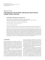
built based on Wiering’s model [14] as shown in Figure 1.
There are six possible settings for each traffic controller
to prevent accidents: two traffic lights from opposing
directions allow cars to go straight ahead or to turn right
(2 possibilities), two traffic lights in the same direction of
the intersection allow the cars from there to go straight
ahead, turn right, or turn left (4 possibilities). Road lanes
are discretized into a number of cells at each traffic light.
The capacity of each road lane is determined according
to its pr actical length. At each time step, new cars with
particular destinations are generated and enter the network
from outside. After new cars have been added, trafficlight
decisions are made and each car moves to the subsequent
cell if it is not occupied or the car’s predecessor is moved
forward. All vehicles are assumed to have the same speed
in this system. Thus, each car is at a specific trafficnode
(node), a direction at the node (dir), a position in the queue
(place), and has a particular destination (des). Thus, we
can use [node, dir, place, des] ([n, d, p, des] for short) to
denote the state of each vehicle [13]. Vehicles follow the
shortest path through the road network to their destinations.
As mentioned before, a multiobjective control scheme is
adopted in this method. The optimization objectives include
the total waiting time, vehicle stops, and the queue length,
which will be chosen adaptively to the traffic condition. We
use Q([n,d,p,des],action)todenotethetotalexpectedvalue
of the optimization objective for each car until it arrives at
the destination given its current node, direction, place and
the decision of the light. The optimal action of a node j is
determined by the following formulation:
A
opt
j
= arg max
A
j
i ∈A
j
(
n,d,p,des
)
∈ queue
i
Q
n, d, p, des
,red
−
Q
n, d, p, des
,green
.
(1)
It should be noticed that Q([n,d,p,des],action) here does
not only refer to the total waiting time but also refer to
vehicle stops or queue lengths, according to the real-time
traffic states. This is the most important difference between
our model and Wiering’s model, which will be explained in
detail in Section 4.
3. Traffic Information Exchange System Using
Vehicular Ad Hoc Network
We need to exchange a lot of information during the signal
control process. Thus, a wireless t raffic information exchange
system based on a vehicular ad hoc network is built to
exchange data among the vehicles and signal controllers.
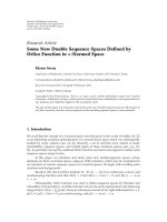
An illustration of such information exchange system is
showed in Figure 2. It is assumed that all vehicles in the
network are intelligent ones equipped with Vehicular Ad
Hoc Network communication devices, so that they have
the ability of communicating with other vehicles and the
roadside controllers. Thus, all necessary information can be
collected through the intercommunication of vehicles and
controllers. The data to b e collected include the followings:
(a) traffic flow through each intersection within each
time step;
(b) queue length at each traffic light within each time
step;
(c) type of each vehicle (car, bus, or emergent vehicle);
(d) destination of each vehicle;
(e) node where each vehicle stands at;
(f) direction each vehicle moving towards;
EURASIP Journal on Advances in Signal Processing 3
Figure 1: Agent-based traffic model illustration.
Wireless
network
Controller
Trafficcontrol
center
Figure 2: Illustration of traffic information exchange system.
(g) p osition in the queue where each vehicle stands at;
(h) total waiting time each vehicle used to pass through
the network;
(i) total number of stops each vehicle used to pass
through the network.
4. Multiobjective Control Algorithm Based on
Reinforcement Learning (Multi-RL)
We extend Wiering’s algorithm to a multiobjective scheme
by selecting the optimization objective according to the real-
time traffic condition. In addition, it is assumed that some
special vehicles such as buses and ambulances need a priority
control, and thus they should b e considered separately.
The multiobjective control algorithm considers three
types of traffic conditions as follows. The method to estimate
traffic conditions should be defined carefully according to the
actual situation of the road network.
4.1. Free Traffic Condition. Under this condition, we aim to
minimize the number of stops, in other words, we expect to
have the vehicles pass through the network with the fewest
stops. Thus, the cumulative number of stops is selected as
the optimization objective.
The number of stops will increase when a vehicle
moving to a green light at current time step meets a red
light at the next time step. Therefore, we denote Q([node,
dir,pos,des],L) as the expected cumulative number of stops
while V([node, dir, pos, des]) denotes the number of stops
(without knowing the traffic light decision) for a car at
[node, dir, pos] until it reaches its destination. The iterative
formulation of Q([node, dir, pos, des], L) is shown as follows:
Q
node, dir, pos, des
, L
=
(
node
,dir
,pos
, L, L
)
P
L
|
node, dir, pos, des
, L,
node
, dir
,pos
,des
×
R
node, dir, pos, des
,
node
, dir
,pos
,des
+γV
node
, dir
,pos
,des
,
V
node, dir, pos, des
=
L
P
L |
node, dir, pos, des
Q
node, dir, pos, des
, L
,
(2)
4 EURASIP Journal on Advances in Signal Processing
where [node
, dir
,pos
, des] means the state of a vehicle at
the next time step; L is the action of the trafficlightat
the current time step, while L
is the action of the traffic
light at the next time step. P(L
| [node, dir, pos, des], L,
[node
, dir
,pos
, des]) gives the probability that the traffic
light turns L
at the next time step given the current state
and the next state of this vehicle; R([node, dir, pos, des],
[node
, dir
,pos
, des]) is a reward function as follows: if L =
Green, L
= Red, which means the vehicle moving to a green
light at the current time step meets a red light at the next time
step, then the number of vehicle stops will increase, R
= 1;
otherwise, R
= 0; γ is the discount factor (0 <γ<1) which
ensures that the Q-values are bounded. The probability that
atraffic light turns red is calculated as follows:
P
L
|
node, dir, pos, des
, L,
node
, dir
,pos
,des
=
C
node, dir, pos, des
, L,
node
, dir
,pos
,des
, L
C
node, dir, pos, des
, L,
node
, dir
,pos
,des
,
(3)
where C([node, dir, pos, des], L,[node
, dir
,pos
,des])
means the number of times a car in the state of [node,dir,
pos, des] transiting to the state of [node
, dir
,pos
,des]
and the transiting light is L, C([node, dir, pos, des], L,
[node
, dir
,pos
,des],L
) is the number of times the light
turns L
after such a transiting procedure.
4.2. Medium Traffic Condition. Under this medium traffic
condition, we focus on the overall waiting time of vehi-
cles, which is the same as in Wiering’s model [13, 14].
Q([node, dir, pos, des], action) is used to denote the total
waiting time before all traffic lights for each car until it
arrives at the destination given its current state and the
action of the light. V([node, dir, pos, des]) denotes the total
waiting time (without knowing the traffic light decision)
for a car at [node, dir, pos]until it reaches its destination.
Q([node, dir, pos, des], action) and V([node, dir, pos, des])
are iteratively updated as follows:
V
node, dir, pos, des
=
L
P
L |
node, dir, pos, des
Q
node, dir, pos, des
, L
,
(4)
Q
node, dir, pos, des
, L
=
(
node
,dir
,pos
)
P
node, dir, pos, des
, L,
node
, dir
,pos
,des
×
R
node, dir, pos, des
,
node
, dir
,pos
,des
+γV
node
, dir
,pos
,des
,
(5)
where L is the traffic lig ht state (red or green), P(L
|
[node, dir, pos, des]) is calculated in the same way as (3),
R([node, dir, pos, des], [node
, dir
,pos
, des]) is defined as
follows: if a car stays at the same place, then R
= 1, otherwise,
R
= 0(thecarcanmoveforward).
4.3. Congested Traffic Condition. Under the congested traffic
condition, we must do our best to avoid the queue spillovers,
which will seriously degrade the trafficcontroleffect and
probably cause large-scale trafficcongestion[15]. Therefore,
the queue length is taken into consideration when we design
the Q learning procedure. Denote the maximum queue
length at the next trafficlighttl
as K
tl
, shortly written as
K. When the traffic light is red, no vehicle can pass through
to the next light. Thus, the equations at a red light do not
change, we focus on the function when light is green. Then
(5) can be rewr itten as follows:
Q
node, dir, pos, des
,Green
=
(
node
,dir
,pos
)
P
node, dir, pos, des
,Green,
node
, dir
,pos
,des
×
R
node, dir, pos, des
,
node
, dir
,pos
,des
+ αR
node, dir, pos, des
,
node
, dir
,pos
,des
+γV
node
, dir
,pos
,des
,
(6)
Q
node, dir, pos, des
,Red
=
(
node
,dir
,pos
)
P
node, dir, pos, des
,Red,
node
, dir
,pos
,des
×
R
node, dir, pos, des
,
node
, dir
,pos
,des
+γV
node
, dir
,pos
,des
,
(7)
where Q([node, dir, pos, des], L)andV([node, dir, pos, des])
have the same meanings as under the medium traffic
condition. Compared (6)with(5), another reward func tion
R
([node, dir, pos, des], [node
, dir
,pos
,des]) is added to
indicate the influence from traffic condition at the next light.
R([node, dir, pos, des], [node
, dir
,pos
, des]) is the reward
of vehicles’ waiting time while R
([node, dir, pos, des],
[node
, dir
,pos
, des]) indicates the reward from the queue
length increasing at the next traffic light. The parameter α is
an adjusting factor.
R([node, dir, pos, des], [node
, dir
,pos
,des]) is defined
as follows: if a car stays at the same place, then R
= 1,
otherwise, R
= 0 (the car c an move forward).
R
([node, dir, pos, des], [node
, dir
,pos
,des])isdefined
as follows: if a car passes through the current intersection to
the next traffic l ight, which means that the queue length at
EURASIP Journal on Advances in Signal Processing 5
the next traffic light will increase by 1 in a short time, then
R
= 1, otherwise, R = 0.
Given the capacity of the lane of next traffic light is L,
then the adjusting factor α is determined by the queue length
K
tl
as follows. Note when queue spillovers happen, K
tl
will
be larger than L [15]
α
=
⎧
⎪
⎪
⎪
⎪
⎪
⎨
⎪
⎪
⎪
⎪
⎪
⎩
0, if K
tl
≤ 0.8L,
10
K
tl
L
− 0.8
,if0.8L<K
tl
≤ L,
2, if K
tl
>L.
(8)
Through the definition we can find that α will increase
sharply when the queue length approaches the capacity of
the lane, which means that queue spillovers would like
to happen. Thus, under such a situation, Q([node, dir,
pos, des], Green) will increase sharply and make the gain
of this policy decrease. Therefore, the green phase length
and the number of vehicles allowed to pass through will be
decreased until the queue at the next light has been dispersed.
The largest value of α is set to 2 in this paper, but you can
adjust its v alue according to the practical traffic condition.
4.4. Priority Control for Buses and Emergency Vehicles. When
buses or emergency vehicles (fire trucks or ambulances)
enter the road network, they should have a priorit y to pass
through. It is necessary to realize the priority control of these
special vehicles with least disturbance to the regular traffic
order.Thus,werevise(5)asfollows.Apriorityfactorβ
is added to describe the emergency degree of these special
vehicles, which needs to be determined separately by the
traffic management department
Q
node, dir, pos, des
, L
=
(
node
,dir
,pos
)
P
node, dir, pos, des
, L,
node
, dir
,pos
,des
×
βR
node, dir, pos, des
,
node
, dir
,pos
,des
+γV
node
, dir
,pos
,des
.
(9)
5. Case Studies
We have done some case studies to prove the effectiveness
of our model. Since it is very hard to apply a model to
the real traffic system management, traffic simulation is
chosen to do the case studies. Paramics V6.3 was selected
as the simulation platform because it is a professional traffic
simulation tool which is recognized by traffic engineers all
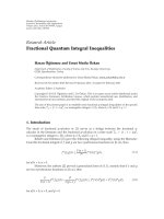
over the world. A pr actical road network within Beijing
Second Ring Road was modeled in Paramics as shown
in Figure 3. This is a network with 7 intersections (N1–
N7) and 8 OD zones (Zone1–Zone8). Intersections N1–N7
correspond to the real intersections Xiaoweihutong, Dong-
dansantiao, Jingyuhutong, Dengshidongkou, Dengshikou,
Wangfujingbeikou, and Taiwanfandian.
N5
N4
N6
N3N2
N1 N7
Zone1
Zone2
Zone3
Zone4
Zone5
Zone6
Zone7
Zone8
Figure 3: Sketch diagram of a practical road network in Beijing.
The simulation ran for 10000 time steps, the first 4000
steps made up the learning process, and the latter 6000 steps
was used to collect the simulation results. Factor γ is set to
be 0.9 and β is set to be 3. The lanes in the network are
divided into cells with length of 7.5 m. The capacity of the
lanes equals to the number of the cells.
We compared our method with the fixed control, the
actuated control and also Wiering’s method. The setting of
fixed control is as follows, the cycle is 2 minutes and the green
time is equally assigned to all phases. In the actuated control
strategy, the minimum green time is 10 s, the maximum
green time is 50 s, and the extension of green time is set to 4 s.
Parameters of Wiering’s method are the same as our model
under the medium traffic condition.
We wanted to estimate the effectiveness of the mul-
tiobjective scheme, thus, we estimated the control effects
of these four algorithms under different traffic conditions.
We changed the traffic volume entering the network every
minute from 30 to 270 and estimated the average waiting
time, the number of stops, and maximum queue length of
these four methods.
In our model, when the traffic volume entering the
network in a minute is less than 90, it is regarded as the
free traffic; when the volume is larger than 90 but less than
180, it is regarded as the medium traffic; when the traffic
volume is larger than 180, it is regarded as the congested
traffic condition.
5.1. Comparison of the Number of Stops. The comparison of
the number of stops with respect to the increasing of traffic
volume is shown in Figure 4. Fixed means the fixed control
strategy, actuated means the vehicle actuated method, RL
means the algorithm proposed by Wiering [13, 14], and
multi-RL means the model proposed in this paper.
It is obvious that when the traffic volume is less than
90, which means that the traffic state is free. The number
of stops under the multi-RL control is less than those under
other control strategies. This is because the multi-RL is
6 EURASIP Journal on Advances in Signal Processing
0 50 100 150 200 250 300
1
2
3
4
5
6
7
Traffic volume
Average stops
Fixed
Actuated
RL
Multi-RL
Figure 4: Control effects comparison estimated by average stops.
the only one that aims to minimize the number of stops.
However, with the increase of traffic volume, the multi-RL
method changes its objective, and the actuated control gets
the minimum stops.
5.2. Comparison of the Average Waiting Time. The com-
parison of the average waiting time with respect to the
increasing of traffic volume is shown in Figure 5. Since
the multi-RL is the same as the RL method under the
medium traffic condition, they have almost the same average
waiting time in the middle. Under the free traffic state,
the RL gets the minimum waiting time because this is its
optimization objective. It should be noticed the multi-RL
gets the minimum waiting time when the traffic is congested.
This indicates that although the RL aims to minimize the
waiting time, the queue spillover which is not considered will
decrease the tr afficefficiency and increase the waiting time.
5.3. Comparison of Maximum Queue Length. The compari-
son of the average waiting time w ith respect to the increasing
of traffic volume is shown in Figure 6. The maximum queue
length exceeds 40 under the fixed control, which indicates
that there must be some queue spillovers. This is taken into
consideration in the multi-RL, thus, we get a short queue
under the congested traffic condition.
6. Conclusion
In this paper, a multiobject ive control algorithm based on
reinforcement learning is proposed. The simulation results
indicate that the multi-RL gets the minimum stops under
the free traffic, though not the minimum waiting time;
the multi-RL has almost the same performance with the
0 50 100 150 200 250 300
Traffic volume
Fixed
Actuated
RL
Multi-RL
150
200
250
300
350
400
Average waiting time
Figure 5: Control effects comparison estimated by average waiting
time.
0 50 100 150 200 250 300
Traffic volume
Fixed
Actuated
RL
Multi-RL
Maximum queue length
0
5
10
15
20
25
30
35
40
45
Figure 6: Control effects comparison estimated by maximum
queue length.
RL method under the medium traffic, which is better than
the fixed control and the actuated control; under congested
condition, the multi-RL can effectively prevent the queue
spillovers to avoid large-scale traffic jams. It should be also
noticed that multi-RL is a car-based algorithm. Therefore,
it is less time consuming than the light-based reinforcement
learning algorithms [13].
EURASIP Journal on Advances in Signal Processing 7
However, there are still some system parameters that
should be carefully determined by hand, for example, the
adjusting factor α indicating the influence of the queue at
next traffic light to the waiting time of vehicles at current
light under the congested traffic condition. This is a very
important parameter, which we should further research its
determining way based on the traffic flow theory. In addition,
some phenomena in real traffic system such as the lane
changing and overtaking of cars will influence their travel
time. The assumption that all vehicles run at the same
speed is also not so reasonable. We would take these into
consideration and build a model closer to the real traffic
system in future work. Besides, the communications between
traffic signal controllers will help to observe the network-
wide traffic states and predict future traffic conditions, which
will improve the trafficcontroleffect and should be further
researched in the future.
Acknowledgments
This work is supported by the National High Technology
Research and Development Program (“863” Program) of
China, Contract no.s 2006AA11Z229, 2007AA11Z215; by the
Key Project of Chinese National Programs for Fundamental
Research and D evelopment (973 program), Contract no.
2006CB705506; by Chinese National Natural Science Foun-
dation, Contract nos. 60834001, 60774034.
References
[1] C. P. Pappis and E. H. Mamdani, “Fuzzy logic controller for
atraffic junction,” IEEE Transactions on Systems, Man and
Cybernetics, vol. 7, no. 10, pp. 707–717, 1977.
[2] M. B. Trabia, M. S. Kaseko, and M. Ande, “A two-stage fuzzy
logic controller for traffic signals,” Transportat ion Research
Part C, vol. 7, no. 6, pp. 353–367, 1999.
[3] J. C. Spall and D. C. Chin, “Traffic-responsive signal timing
for system-wide traffic control,” Transportation Research Part
C, vol. 5, no. 3-4, pp. 153–163, 1997.
[4] Z. Liu, “Hierarchical fuzzy neural network control for large
scale urban t rafficsystems,”Information and Control, vol. 26,
no. 6, pp. 441–448, 1997.
[5] M. D. Foy et al., “Signal timing determination using genetic
algorithms,” Transportation Research Record 1365, National
Research Council, Washington, DC, USA, 1992.
[6] B. Park et al., “Enhanced genetic algorithm for signal timing
optimization of oversaturated intersections,” Transportation
Research Record 1727, National Research Council, Washing-
ton, DC, USA, 2000.
[7] R. S. Sutton, “Learning to predict by the methods of temporal
differences,” Machine Learning, vol. 3, no. 1, pp. 9–44, 1988.
[8] C. Watkins, Learning from delayed rewards, Ph.D. thesis, King’s
College, Cambridge, UK, 1989.
[9] L. P. Kaelbling, M. L. Littman, and A. W. Moore, “Rein-
forcement learning: a survey,” Journal of Artificial Intelligence
Research, vol. 4, pp. 237–285, 1996.
[10] T. Thorpe, Vehicl e t ra ffic light control using SARSA, M.S. thesis,
Colorado State University, 1997.
[11] B. Abdulhai, R. Pringle, and G. J. Karakoulas, “Reinforcement
learning for true adaptive traffic signal control,” Journal of
Transportation Engineering, vol. 129, no. 3, pp. 278–285, 2003.
[12] S. Mikami and Y. Kakazu, “Genetic reinforcement learning for
cooperative traffic signal control,” in Proceedings of the 1st IEEE
Conference on Evolutionary Computation, vol. 1, pp. 223–228,
Orlando, Fla, USA, June 1994.
[13] M. Wiering et al., “Intelligent traffic light control,” Tech. Rep.
UU-CS-2004-029, University Utrecht, 2004.
[14] M. Wiering, “Multi-agent reinforcement learning for traffic
light control,” in Proceedings of the 17th International Confer-
ence on Machine Learning (ICML’ 2000), pp. 1151–1158, 2000.
[15] C. F. Daganzo, “Queue spillovers in transportation networks
with a route choice,” Transportation Science,vol.32,no.1,pp.
3–11, 1998.