Báo cáo hóa học: " Research Article Interference Management Schemes for the Shared Relay Concept" docx
Bạn đang xem bản rút gọn của tài liệu. Xem và tải ngay bản đầy đủ của tài liệu tại đây (1014.68 KB, 14 trang )
Hindawi Publishing Corporation
EURASIP Journal on Advances in Signal Processing
Volume 2011, Article ID 269817, 14 pages
doi:10.1155/2011/269817
Research Article
Interference Management Schemes for the Shared Relay Concept
Ali Y. Panah, Kien T. Truong, Steven W. Peters, and Robert W. Heath Jr.
Department of Electrical and Computer Engineering, The University of Texas at Austin, University Station C0806,
Austin, TX 78712-0240, USA
Correspondence should be addressed to Ali Y. Panah,
Received 30 June 2010; Accepted 8 September 2010
Academic Editor: Robert Schober
Copyright © 2011 Ali Y. Panah et al. This is an open access article distributed under the Creative Commons Attribution License,
which permits unrestricted use, distribution, and reproduction in any medium, provided the original work is properly cited.
Sharing a multiantenna relay among several sectors is a simple and cost-effective way to achieving much of the gains of local
interference mitigation in cellular networks. Next generation wireless systems, such as ones based on the Third Generation
Partnership Projects Long-Term Evolution Advanced, will employ universal frequency reuse to simplify network deployment.
This strategy is anticipated to create significant cell-edge interference in the location of the shared relays, thus rendering advanced
interference management strategies a necessity. This paper proposes several interference management strategies for the shared
relays ranging from simple channel inversion at the relay, to more sophisticated techniques based on channel inversion in
combination with partial and full base station coordination in the downlink and uplink. Given that the relay functionality
influences total interference, both amplify-and-forward and decode-and-forward type relays are considered throughout. In this
context, channel cancelation techniques are investigated for one-way relaying and also the spectrally efficient two-way relaying
protocol. Simulations show that strategies based on two-way shared relaying with bidirectional channel inversion at the relay often
perform best in terms of total system throughput while one-way techniques are promising when the relay power is low.
1. Introduction
The IEEE 802.16j wireless standard was one of the first
commercial standards to embrace the use of relay terminals
within a cellular network [1]. The use of relay terminals
is also provisioned in many upcoming wireless standards
such ones emerging from the Third Generation Partnership
Program’s Long-Term Evolution Advanced (3GPP LTE-A)
task group [2–7]. Such deployments are expected to operate
under universal frequency reuse patterns so as to maximize
area spectral efficiency. Intercell interference, therefore, is
omnipresent throughout the network and interference man-
agement strategies such as intercell interference coordination
[8–12] are of utmost importance in realizing the true gains
promised by the standards. While to facilitate interference
management, certain means of exchanging information via
the X2 interface connecting the base stations have been
foreseen in 3GPP LTE-Advanced, practical considerations
(such as latency) warrant more research toward interference
management at the relay terminals.
Within this context, previously in [7] we evaluated the
benefits of several promising relaying strategies for 3GPP
LTE-Advanced including: one-way shared relaying, two-way
relaying, and IEEE 802.16j relaying. Our simulations revealed
some key behaviors pertinent to each relaying scheme. The
two-way relaying strategy, for instance, exhibited severe
interference enhancement in both the uplink and downlink
transmissions. This was not surprising since the strategy
here was to amplify and forward all received signals at the
relays; the amplification process simply did not differentiate
between desired signal and interfe rence (or even noise).
Even after the subtraction of self-interference (as a benefit
to two-way relaying), considerable intersector and intercell
interferences aggregated at the receivers. The demodulation
processes were subsequently severely degraded, resulting in
relevantly low total sum rates. To make matters worse,
each sector in each cell contained a two-way relay terminal
which individually contributed to such interferences. The
“sharedrelayconcept”,however,provedtobewellsuited
to handle such interferences, providing adequate sum rate
performances comparable even to base station cooperation
schemes. Two factors undoubtably attributed to the success
of the shared relay concept: (i) interference cancelation:
the shared relay did not simply forward signals to the
2 EURASIP Journal on Advances in Signal Processing
destination, it first decoded and demodulated the received
signals in the presence of interference, and subsequently
forwarded a virtually “interference-free” signal to the desti-
nation; a process known as decode and forwarding in relay
literature and (ii) minimal infrastructure: unlike the two-
way relaying scheme (also the one-way 802.16j scheme), the
shared relay concept, by virtue of its name, was physically
shared between several sectors throughout the network.
Naturally, less relays were deployed within the network
leading not only to possible network cost reduction, but
perhaps more importantly the potential to reduce total
interference caused by such terminals. As a result, the shared
relay concept exhibited a kind resiliency to interference very
much desired from a systems design perspective (see, e.g.,
Figure 8 of [7]). These benefits, however, come at the expense
of increased complexity both at the relays, to perform
successive interference cancelation, and at the base stations,
to perform dirty paper coding. The need for coordination
within the shared sectors and issues in synchronization add
to these concerns, diminishing the prospects of practical
implementation using current hardware capabilities.
In this paper, we expand upon our original shared relay
concept to include more intelligent interference management
strategies. The main contributions of this paper are as
follows. For the one-way shared relay, and in contrast to
dirty-paper coding and successive interference cancelation,
we reformulate the transmissions to and from the relay
to include more practical linear techniques such as zero-
forcing precoding and zero-forcing combining (reception).
For one-way nonshared (IEEE 802.16j-type) relaying, we
include a formulation based on base station coordination
via multi-cell cooperative processing, where the coordinated
base stations form one virtual antenna array [13–16]. Here,
we consider channel inversion (zero-forcing) in the downlink
and joint processing to form a multiple-antenna multiple
access channels in the uplink. The combination of these
strategies improves upon the performance of naive decode
and forwarding in our previous work, especially when the
receivers are close to the relay terminals. Finally, inspired by
observations regarding the original shared relay concept (as
briefly touched upon above) the two-way relaying strategy is
enhanced in several ways. Firstly, instead of including a relay
in each sector of each cell, we resort to a shared two-way relay
model. Secondly, we consider interference management, and
specifically interference cancelation, at each relay. In this way,
the two-way relay will hopefully benefit from the interference
cancelation and minimal infrastructure attributes enjoyed by
the original shared relay concept.
We also acknowledge, and address, the important fact
that the original two-phase two-way protocol has potential
power-masking problems, meaning the downlink signals
might mask the uplink signals in terms of received power at
the relay. This is an artifact of the two-phase protocol where
the uplink and downlink signals are received simultaneously
at the two-way relay. As a consequence, if the relay makes
an effort, for example, to decode the uplink signals, it must
do so under extreme interference owing to the downlink
transmission. As a remedy, we relax the simultaneous
transmission protocol required by the two-way protocol and
instead include a three-phase protocol in which the uplink
and downlink transmissions are received at different time
slots by the relay. While the three-phase protocol takes a hit in
terms of multiplexing gain it is still appealing in many ways
compared to the two-phase counterpart. A full treatment
of this topic is beyond the scope of this paper, we simply
note that the three-phase protocol provides the relay with
individual processing capabilities of the uplink-downlink
signals. As a consequence, the relay has the potential, for
example, to distribute its available resources (such as power)
differently between the uplink and downlink streams as it
broadcasts its common message in the third phase (time
slot). The details of this process will become apparent in the
two-way relaying section.
The rest of the paper is organized as follows. Section 2
presents the system model while Sections 3 and 4 are
devoted to details leading to sum rate expressions for the
one and two-way proposed strategies. In Section 5 we
present Monte-Carlo simulations assessing the performance
of our solutions along with discussion. Finally, Sections 6
and Acknowledgment give summarizing comments and
acknowledgments, thus concluding the paper.
This paper uses the following notations. Bold uppercase
letters, such as A denote matrices, bold lowercase letters, such
as a denote column vectors, and normal letters a denote
scalars. The notation A
∗
denotes the Hermitian transpose
of matrix A. The letter
E denotes expectation, min{a, b}
denotes the minimum of a and b, |a| is the magnitude of
the complex number a,and
a
2
2
is the Euclidean norm of
vector a.
2. System Model
2.1. General System Model. Consider a network where the
cells are labeled by the set C
={1,2, , C}, such that C =
|
C| denotes the total number of cells. Each cell contains a
single base station (BS) with N
t
transmit antennas. Moreover,
each cell is sectorized and the sectors of the ith cell are
labeled by the set S
i
={1,2, , S},whereS =|S| is the
total number of sectors per cell. For simplicity, we assume
equal numbers of BS antennas and sectors in all the cells
and that each sector contains a single mobile station (MS).
Each BS antenna (corresponding to a sector) transmits one
data stream in the downlink (DL) to the MS in its sector
and receives a single stream in the uplink from that MS. The
DL/UL transmissions occur in nonoverlapping time intervals
in TDMA fashion, that is, time-sharing.
2.2. Shared Relay Model. At the joint corner of any three
adjacent cells there exists a single relay terminal equipped
with N
r
antennas. Such shared relays are labeled by the set
M
={1, 2, , M}. The purpose of each shared relay is to
assist, that is, coordinate, the DL and/or UL transmissions
occurring in its assigned adjacent cells.
Specifically, the shared relay assists the transmission in a
subset of sectors in the adjacent cells. For example, consider
the mth shared relay in coordination with adjacent cells
labeled by A
m
={m
1
, m
2
, m
3
}⊂C.Let
S
m
1
⊆ S
m
1
,
S
m
2
⊆
S
m
2
and
S
m
3
⊆ S
m
3
denote subsets of sectors in these cells
EURASIP Journal on Advances in Signal Processing 3
Base station antennas
Shared relay stations
Mobile stations
(a)
Base station antennas
Shared relay stations
Mobile stations
Boundaries of combined sectors
served by coordinated BSs
(b)
Base station antennas
802.16j-like relay stations
Mobile stations
Boundaries of combined sectors
served by coordinated BSs
(c)
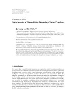
Figure 1: System models for (a) shared relaying (one-way and two-way), (b) shared relaying with BS cooperation (one-way) and (c)
nonshared, 802.16j, relaying with BS cooperation.
that are being coordinated. Here, we denote the “sectors of
interest” for this shared relay by the set
S
m
=
S
m
1
∪
S
m
2
∪
S
m
3
.
For simplicity, we assume henceforth that each shared relay
coordinates an equal number of sectors denoted by N
c
=
|
S
m
|, m = 1,2, , M. Also since we assume that each MS
has one antenna, each sector of each BS transmits only a
single data stream. Figure 1(a) shows a typical scenario which
we consider in our simulations consisting of a 3-cell network
(C
= 3), with each cell sectorized into S = 6sectorsand
three center sectors, that is, N
c
= 3, coordinated by a single
(M
= 1) shared relay.
2.3. Nonshared (IEEE 802.16j-type) Relay Model. We
describe in this section a scenario where IEEE 802.16j-
type relays are used to help the transmission between
cooperative base stations and their associate mobile stations.
For fair comparison and practicality, we assume localized
coordination among the base stations serving the same
sectors of interest as in the other architectures. In particular,
we assume that there exists a half-duplex decode and forward
relay in each sector aiding the data transmission between the
base station antenna and one single-antenna mobile station.
Moreover, we assume that base station coordination are
deployed for intersector interference management (perhaps,
intercell interference management if the sectors belong to
different cells) for N
c
adjacent sectors, for example, the
three center sectors in Figure 1(c).TheN
c
sectors are of our
interest. For notational convenience, the nodes associated
with the kth sector of interest are labeled as BS
k
,RS
k
and MS
k
for k = 1, , N
c
. The transmissions in the other sectors are
assumed to be uncoordinated and thus cause interference to
the signal reception in the N
c
sectors of interest. Let N
i
be the
number of uncoordinated sectors. We will interchangeably
use the terms “802.16j” and “nonshared relay” for modeling
this type of relay configuration throughout the paper.
3. One-Way Relaying Schemes
In this section, we present two classes of interference
management solutions for one-way cellular relaying. In one
scheme, which we call one-way shared relaying, the shared
relay model as described in Section 2.2 is utilized. The basis
for this scheme is the shared relay concept explained in
depth in [7], where we evaluated the system employing high-
complexity techniques such as the use of dirty paper coding
and joint detection. Here we take a more pragmatic approach
to the shared relay concept and formulate the problem using
practical transmission-recepetion techniques such as block
diagonalization transmission and zero-forcing reception. In
this context, we extend the core notion of shared relaying
to include more sophisticated transmission schemes that
include BS coordination. In yet another scheme, which we
simply call one-way nonshared relaying (or 802.16j relaying),
we assume that instead of a shared relay, each sector of
each cell contains a dedicated relay terminal as explained
in Section 2.3; a concept also explained in depth in our
previous work [7]. Here, we extend this scheme to include
BS coordination as a means of interference management and
explain key concepts relating to this configuration.
4 EURASIP Journal on Advances in Signal Processing
3.1. One-Way Shared Relay ing with Base Station Coordina-
tion. A conventional shared relay serves multiple sectors,
communicating with multiple base stations and multiple
mobile stations located in different cells. In this manner,
a shared relay network operates with less total interference
than a conventional tree architecture, where each relay
communicates with only one base station, and intercell
coordination is very limited. This reduced interference comes
with the price of a sophisticated relay with multiple antennas
and the ability to communicate using multiuser MIMO
techniques. The one-way shared relay transmission protocol
was explained in more detail in [7], We begin with a
simple nonbasestation-coordination setup similar to the one
analyzed in [7], where the transmission protocol was divided
into two phases: (i) MIMO multiple access channel (MAC)
and (ii) MIMO broadcast channel (BC). We overview each
phase separately below and in doing so we introduce various
notation used throughout the paper. While our overview is
in the context of the DL transmission, the UL treatments
follows in a similar fashion and is omitted here.
Multiple Access Channel (MAC). Define h
ij
as the length
N
r
channel vector from the BS antenna serving the jth
sector of the ith cell to the shared relay and let s
ij
be
the transmitted symbol from this BS antenna. To allow for
possible powerloading over the sectors of each BS we let
E
s
{s
ij
s
∗
ij
}=P
b
ij
and the signals are uncorrelated across the
antenna arrays and over the BSs. Consider the mth shared
relay, in coordination with cells A
m
. The sectors of interest,
that is, sectors coordinated by the shared relay, are labeled
by
S
m
. Other sectors belonging to the cells in A
m
are termed
“intersectors” and are labeled by
S
I
m
while cells other than
A
m
are termed “intercells”. The received signal at the shared
relay is
y
R
=
C
i=1
S
j=1
h
ij
s
ij
+ n
R
=
i∈A
m
j∈
S
m
h
ij
s
ij
+
intersector interference
i∈A
m
j∈
S
I
m
h
ij
s
ij
+
i
/
∈A
m
S
j=1
h
ij
s
ij
intercell interference
+ n
R
= Hs + ζ
b
+ v
b
+ n
R
,
(1)
where n
R
∼ CN (0, N
0
I) is AWGN at the shared relay.
We dropped the relay index m for convenience in the last
expression and defined the N
r
×N
c
matrix H whose columns
are constructed from h
ij
(for the sectors of interest), and s
as the vector of transmitted symbols from these sectors. The
intersector interference (ISI) and intercell (ICI) terms are is
collected in ζ
b
and v
b
,respectively.
The relay proceeds to decode the transmitted symbols.
With N
r
≥ N
c
, a zero-forcing (ZF) receiver will use a spatial
filter W
DL,1
= H
†
= (H
∗
H)
−1
H
∗
to decouple the streams in
the sectors of interest and decode the signals from the vector
W
DL,1
y
R
. This may be accomplished at an instantaneous sum
rate of
R
DL
1
=
N
c
i=1
log
2
⎛
⎜
⎝
1+
P
b
i
W
DL,1
q
b
q
∗
b
W
∗
DL,1
i,i
⎞
⎟
⎠
,(2)
where P
b
i
is the power of the ith element of s and q
b
=
E
s
{ζ
b
ζ
∗
b
+ v
b
v
∗
b
} + N
0
I
N
r
is the interference-plus-noise
covariance. The UL is characterized similar to the DL, with
the uplink channels (and signals) replacing the downlink
ones. For instance the received signal at the relay in the UL
is y
R
= Gx + ζ
m
+ n
R
,whereG and x are analogues of
H and s in the DL. With W
UL,1
= G
†
= (G
∗
G)
−1
G
∗
and
q
m
= E
x
{ζ
m
ζ
∗
m
+ v
m
v
∗
m
}+ N
0
I
N
r
the UL sum rate in the MAC
phase is
R
UL
1
=
N
c
i=1
log
2
⎛
⎜
⎝
1+
P
m
W
UL,1
q
m
q
∗
m
W
∗
UL,1
i,i
⎞
⎟
⎠
,(3)
where P
m
is the average transmit power of any MS and we
collected all transmissions outside the sectors of interest in
ζ
m
.
Broadcast Channel (BC). Once the relay has decoded the
received signals in the sectors of interest it must broadcast
the information to the MSs in those sectors. While in
[7] we assumed a DPC scheme, here we take a more
pragmatic approach and assume a linear precoder at the
relay. Specifically, we assume the MSs each have a single
antenna and therefore receive a single stream. The precoder
at the relay is then designed to cancel, that is, zero force, the
channel to the MSs. To this end, define g
ij
as the length N
r
channel vector from the jth MS of the ith cell to the shared
relay and assume reciprocal channel so that the channel from
the relay to the MSs in the the sectors of interest is G
∗
. Similar
to H (above), the columns of G are g
ij
for sectors indexed by
S
m
. The transmitted signal from the relay is r = W
DL,2
Γs,
where
s is the decoded signal (assumed to be correct) with
unity energy per element and Γ is a diagonal matrix with
elements γ
i
, i = 1, 2, , N
c
that controls the power for each
element of
s.MoreoverΓ is such that the average transmit
power of P
r
is satisfied at the relay. A ZF filter in this case is
W
DL,2
= G(G
∗
G)
−1
leading to a sum rate of
R
DL
2
=
N
c
i=1
log
2
1+
γ
2
i
N
0
.
(4)
The sum rate of the entire communication link from BS to
MS in the MAC and BC described above is then
R
DL
shared
=
1
2
min
R
DL
1
, R
DL
2
.
(5)
A similar analysis may be done on the UL to obtain
R
UL
shared
=
1
2
min
R
UL
1
, R
UL
2
,
(6)
and the the average sum of the end-to-end rates of both
downlink and uplink is R
sum
shared
= R
DL
shared
+ R
UL
shared
.
EURASIP Journal on Advances in Signal Processing 5
Extension-Base Station Coordination. The shared relay
model does not consider base station coordination.
Joint reception and transmission of disjoint base stations,
however, is becoming a practical option for future generation
networks. Thus, shared relays can be envisioned to operate
in a network with coordinated base stations, so this section
considers such a model for analysis. For this model, we allow
multiple base stations to jointly transmit (downlink) or
receive (uplink) signals to and from the shared relays and
we assume each shared relay still serves N
c
of the mobile
stations (data streams).
In the first hop of the downlink, the model is now
a MIMO broadcast channel, rather than a MAC channel
in the normal shared relay model. Figure 1(b) shows an
embodiment of this scenario where C
= 4 cells, that is, base
stations, are connected via a high capacity backhaul link and
are able to cooperate in real-time (no delay). Here a total
of 6 antennas, that is, S
= 6 sectors, are jointly utilized
to transmit 6 streams intended for the indicated M
= 2
shared relays. Each relay will decode N
c
= 3 independent
streams intended for mobile stations in its sectors of interest.
This broadcast channel may readily be realized via block
diagonalization. The precoding matrix for shared relay m
is in the form of W
(m)
BD
=
V
m
V
m
,where
V
m
lies in the
null space of
H
m
= [H
∗
1
···H
m−1
, H
m+1
···H
∗
M
]
∗
,and
V
m
is the matrix with columns of dominant eigenvectors of
H
m
V
m
.InthiscaseeachrelaywillreceiveN
c
streams, free
of interuser interference. Intersector interference, however, is
still present (along with intercell interference) however fewer
sectors contribute to such interference since a group of such
sectors are now in cooperation. Similar to (1), the received
signal at the shared relay is y
R
=
Hs +
ζ
b
+ v
b
+ n
R
,where
ζ
b
and v
b
are equivalent intersector and intercell interferences.
The sum rate at each shared relay is then
R
DL
1,coop
=
N
c
i=1
log
2
⎛
⎜
⎝
1+
P
b
i
q
b
q
∗
b
i,i
⎞
⎟
⎠
,(7)
where
q
b
= E
s
{
ζ
b
ζ
∗
b
+ v
b
v
∗
b
} + N
0
I
N
r
. In the second
hop of the downlink, the relays are not able to coordinate
their transmissions, so the model resorts to the identical
MIMO broadcast channel of the conventional shared relay
channel. In other words the relays cannot preform zero-
forcing between themselves as was done in the previous phase
by the base stations. Thus, the rate in the second hop of the
downlink (and, conversely, in the first hop of the uplink)
is identical to that of the conventional shared relay channel
with zero-forcing precoding given by (4), R
DL
2,coop
= R
DL
2
,and
the total DL sum rate is
R
DL
coop
=
1
2
min
R
DL
1,coop
, R
DL
2,coop
.
(8)
3.2. One-Way Relaying (802.16 j-type) with Base Station
Coordination. In this section, we compute the sum of the
end-to-end achievable rates for both the uplink and the
downlink in the model of one-way relaying with base station
coordination. This is the (nonshared) 802.16j-type relay
model explain in Section 2.3 and in detail in [7]. The
coordinated base stations are assumed to share perfectly the
data to be transmitted and the knowledge of the channels
between base stations and relays via a high-capacity low-
delay wired backhaul link. The information exchange allows
for multi-cell cooperative processing, where the coordinated
base stations form one virtual antenna array.
We analyze first the downlink transmission. The down-
link transmission requires two nonoverlapping stages. In the
first stage, the base stations coordinate their transmissions
to each relay, forming a multiple-antenna broadcast channel;
while in the second stage, the relays decode their intended
signals, re-encode and forward to the mobile stations,
forming an interference channel. Let s
k
be the symbol to be
transmitted from the N
c
coordinated base stations antennas
to MS
k
such that E{|s
k
|
2
}=P
b
k
and E{s
k
s
∗
j
}=0for
j
/
=k.Wedenoteh
∗
k
,whereh
k
∈ C
N
c
×1
, as the channel
vector from the K coordinated base station antennas to the
kth relay. Similarly, let s
N
i
∈ C
N
i
×1
be the symbol vector
to be transmitted from the N
i
uncoordinated base station
antennas to their associate mobile users. We assume that the
uncoordinated base station antennas use the same transmit
power P
b
, then E{s
N
i
s
∗
N
i
}=P
b
I. Also, we denote θ
∗
k
,where
θ
k
∈ C
N
i
×1
, as the channel vector from the N
i
uncoordinated
base station antennas to the kth relay. Moreover, we assume
n
k
∼ CN (0, N
0
) is the noise vector at the kth relay. For the
first stage of the downlink, although achieving the capacity
of multiple-antenna broadcast channel, the DPC requires an
extensive optimization, leading to significant computational
load and overhead. Instead, for simple analysis and practi-
cality, the channel inversion method is employed. We assume
w
k
∈ C
N
c
×1
is the beamforming vector corresponding to s
k
.
To remove the intersector interference within the cluster of
coordinated sectors, we must have h
∗
j
w
k
= 0forallj
/
=k, that
is, the zero intersector interference constraint. Let us define
the combined channel matrix from the N
c
coordinated base
station antennas to the (N
c
−1) relays other than the kth relay
as
H
k
=
h
1
··· h
k−1
h
k+1
··· h
N
c
∗
.
(9)
Under the zero intersector interference constraint and also
to maximize the desired signal power, w
k
is nothing but the
projection of h
k
onto the null space of H
k
. With the set of
beamforming vectors, the received signal at the kth relay in
the first-hop downlink transmission is written as
r
k
= h
∗
k
w
k
s
k
+ θ
∗
k
s
N
i
+ n
k
.
(10)
The achievable rate of the first-hop downlink transmission
from the N
c
coordinated base station antennas to the kth
relay is
R
DL
1,k
= log
2
⎛
⎜
⎝
1+
P
b
k
h
∗
k
w
k
2
P
b
θ
∗
k
θ
k
+ N
0
⎞
⎟
⎠
.
(11)
In the second stage of the downlink transmission, after
decoding s
k
, the relay in the kth coordinated sector re-
encodes it as x
k
for retransmission to its associate mobile
6 EURASIP Journal on Advances in Signal Processing
station in the same sector. We assume P
r
k
is the transmit
power at the relay in the kth coordinated sector. Let g
k, j
be
the channel from the relay in the jth coordinated sector to
the mobile user in the kth coordinated sector. Moreover, we
denote β
∗
k
,whereβ
k
∈ C
N
i
×1
, as the channel vector from
the relays in the N
i
uncoordinated sectors to the mobile
user in the kth coordinated sectors. We assume that x
N
i
is the transmitted symbol vectors from the uncoordinated
relays. Note that we also have
E{x
N
i
x
∗
N
i
}=P
r
I,where
P
r
is the transmit power at an uncoordinated relay. Let
v
k
∼ CN (0, N
0
) be the noise at the mobile user in the kth
coordinated sector. The mobile user in the kth coordinated
sector receives
y
k
= g
k,k
x
k
+
j
/
=k
g
k, j
x
j
+ β
∗
k
x
N
i
+ v
k
.
(12)
The achievable rate of the second-hop downlink transmis-
sion in the kth coordinated sector is
R
DL
2,k
= log
2
⎛
⎜
⎝
1+
P
r
k
g
k,k
2
j
/
=k
P
r
j
g
k, j
2
+ P
m
β
∗
k
β
k
+ N
0
⎞
⎟
⎠
.
(13)
We now analyze the uplink transmission in which the kth
mobile station transmits
s
k
to the kth base station. The uplink
transmission also requires two stages. In the first stage, the
mobile stations transmit signals to the relays, forming an
interference channel; and in the second phase, the relays
forward the signals to the base stations, which cooperate
to perform joint processing to form a multiple-antenna
multiple access channel. Let
g
k, j
be the channel from the
mobile station in the jth coordinated sector to the relay in
the kth coordinated sector and φ
∗
k
,whereφ
k
∈ C
N
i
×1
,be
the channel from the mobile users in the N
i
uncoordinated
sectors to the relay in the kth coordinated sector. Similar to
the second-hop downlink channel, we obtain the achievable
rate of the first-hop uplink channel from the kth mobile
station to the kth relay is
R
UL
1,k
= log
2
⎛
⎜
⎝
1+
P
m
k
g
k,k
2
j
/
=k
P
m
j
g
k, j
2
+ P
m
φ
∗
k
φ
k
+ N
0
⎞
⎟
⎠
.
(14)
In the second stage of the uplink transmission, we have
a multiple-antenna multiple access channel since the base
stations can cooperate for joint reception. After decoding
s
k
, the kth relay re-encodes it as x
k
(with E{|x
k
|
2
= P
r
k
})
according to the highest rate supported by the transmission
from the kth relay to the N
c
coordinated base station
antennas. Let
H
k
∈ C
N
c
×N
c
be the channel matrix from the
relays in the N
c
coordinated sector to the N
c
coordinated
base station antennas. We denote Ψ
k
∈ C
N
c
×N
i
as the channel
matrix from the relays in the uncoordinated sectors to the N
c
coordinated base station antennas and x
N
i
as the transmitted
symbol vector from the relays in the N
i
uncoordinated
sectors. The received signal at the N
c
coordinated base station
antennas is
y =
H
k
x
k
+ Ψ
k
x
N
i
+ z,
(15)
where
x
k
= [x
1
···x
N
c
]
T
∈ C
N
c
×1
and z is the noise vector
at the N
c
coordinated base station antennas. We assume the
zero-forcing receiver W
= (
H
∗
H)
−1
H is applied to y to
decouple the data streams. The achievable data rate in the
second-hop of the uplink is given by
R
UL
2,k
= log
2
1+
P
r
k
W
Ψ
k
Ψ
∗
k
+ N
0
W
∗
k,k
.
(16)
We a ssume t
∈ (0, 1) be the fraction of time used for the first-
hop transmission in the downlink and hence (1
− t) is that
for the second-hop transmission in the downlink. The end-
to-end achievable rate of the two-hop downlink transmission
from the kth base station to the kth mobile station via the
kth relay station is R
DL
k
= (1/2) min{R
DL
1,k
, R
DL
2,k
}, where for
fair comparison with the other approaches in the paper,
we assume that equal time sharing for two hops in both
directions is used. In other words, we have
R
DL
nonshared
=
N
c
k=1
1
2
min
R
DL
1,k
, R
DL
2,k
.
(17)
This is analogous to (8) for the shared relay model. Similarly,
the end-to-end achievable rate in the uplink is R
UL
k
=
(1/2) min{R
UL
1,k
, R
UL
2,k
} with
R
UL
nonshared
=
N
c
k=1
1
2
min
R
UL
1,k
, R
UL
2,k
,
(18)
and the average sum of the end-to-end rates of both dow-
nlink and uplink is R
nonshared
sum
= R
DL
nonshared
+ R
UL
nonshared
.
4. Two-Way Relaying Schemes
In this section, we present three classes of interference
management solutions for two-way cellular relaying. Two-
way relaying differs from its one-way counterpart mainly
in the structure of the UL-DL transmission protocol (see
[17–22] for an overview of two-way relaying). Figure 2
highlights this difference, illustrating how the UL and DL
transmissions are time-multiplexed (as is assumed in this
paper), the one-way relaying scheme requires a total of four
time slots while the two-way relaying protocol only requires
three. In this regard the two-way protocol is potentially more
spectrally efficient than its one-way counterpart. Specifically,
one complete UL-DL transmission in the two-way protocol
proceeds as follows: (i) the BS transmits a signal to the
relay while the MS is silent, that is, the DL, (ii) the MS
transmits its signal to the relay while the BS is silent, that
is, the UL and (iii) the relay jointly processes the DL and UL
signals and proceeds to broadcast a unified signal to the BS
and MS. After such, the BS and MS extract their intended
signals by first canceling their own transmitted signal which
has essentially been “reflected” off the relay. The process
of subtracting this so-called self-interferece is crucial to the
underlying performance of two-way relaying.
In [7] we proposed a two-way protocol in a cellular
setting where we assumed naive signal processing at the
EURASIP Journal on Advances in Signal Processing 7
One-way relaying
DL
DL
UL
UL
(a)
Two-way relaying
DL
UL
UL + DLUL + DL
(b)
Figure 2: One-way and two-way transmission protocols.
relay, meaning that no effort was made on dealing with
interferences other than removing self-interference inherent
to the protocol. As a result the performance of the two-way
protocol was severely undermined by intercell and intersec-
tor interferences (see, e.g., Figure 8 of [7]). As a remedy, we
now propose more sophisticated relay processing techniques
tailored for the shared relay model (see Section 2.2). As our
simulations show, such efforts may dramatically improve
the performance of two-way relaying in interference limited
cellular settings.
4.1. Decode Superimpose Orthogonalize and Forward (DSOF)
Relaying. As a natural extension of the one-way shared relay
scheme of Section 3, assume that the shared relay decodes
its received signal. In two-way relaying fashion, the following
three-phase scheme is proposed.
Phase I—Downlink. the relay receives DL transmission from
the sectors of interest labeled by
S
m
while the MSs in
these sectors are silent. Denote the received signal in this
phase as y
(I)
R
which is exactly (1). In fact this is precisely
the MAC phase of the previously discussed one-way shared
relay strategy. Again, using a ZF filter to separate the spatial
streams from the BS sectors the sum rate of (2)isachievable.
Phase II—Uplink. The roles of the BS and MSs are reversed
in the sectors of interest. Denote the received signal in this
phase as y
(II)
R
= Gx + ζ
m
+ n
R
which is similar to (1)exempt
formulated for the UL. The MSs each transmit at a power
of P
m
to the relay thus forming another MAC phase at an
achievable rate given by (3).
Phase III—Relay Processing. The relay constructs a single
signal to broadcast to both the BS sectors and the MSs (in the
sectors of interest). Specifically, after decoding the received
signals (assuming the decoding is correct) from phase I and
II the relay re-encodes the messages and subsequently pairs
the signals by superposition at the signal level. For ease of
notation, henceforth consider the three cell network with
a central shared relay and sectors of interest as depicted in
Figure 1(a). Here, the relay is coordinating one sector in each
cell, that is,
|
S
m
|=1. Specifically, the relay coordinates with
the adjacent sectors of each cell which following the notion
of Section 2.2 we assume to be labeled as
S
m
1
=
S
m
2
=
S
m
3
=
{
1}.ClearlyN
c
= 3 in this case and the relay constructs the
following superposition
t
i
= s
i1
1+γ
2
+ x
i1
1 − γ
2
,
−1 ≤ γ ≤ 1,
i
= 1, 2, , N
c
(
= 3
)
.
(19)
Note how the subscript i denotes a pair of BS-MS in the
sector of interest for the ith cell. Next, to spatially separate
such BS-MS pairs between the different cells, the relay assigns
unique beamforming vectors w
i
to each t
i
. The transmitted
vector from the relay is t
R
=
√
P
r
N
c
i=1
w
i
t
i
=
√
P
r
Wt,
where W
Δ
= [w
1
, w
2
, , w
N
c
]withtr(WW
∗
) = 1, t
[t
1
, t
2
, , t
N
c
]
T
,andP
r
is the total average power from the
relay terminal. The signal t
R
is broadcasted to the sectors
of interest pertaining to the corresponding shared relay.
Assuming reciprocity in the channels, the received signal in
the sectors of interest in the ith BS is
y
i
= h
∗
i1
t
R
+ n
i
,
(20)
where n
i
∼ CN (0, N
0
) is AWGN. Similarly, at the ith MS
z
i
= g
∗
i1
t
R
+ v
i
,
(21)
where v
i
∼ CN (0, N
0
) is AWGN. Viewing these signals in
corresponding pairs we define the 2
× 1vectord
i
[y
i
, z
i
]
T
so that
d
i
=
h
i1
g
i1
∗
t
R
+
[
n
i
, v
i
]
T
=
√
P
r
F
i
Wt + n
i
=
√
P
r
F
i
w
i
t
i
+
√
P
r
j
/
=i
F
i
w
j
t
j
+ n
ij
,
(22)
8 EURASIP Journal on Advances in Signal Processing
where F
i
[h
i1
g
i1
]
∗
is a composite BS-MS channel for the
ith cell and n
i
∼ CN (0,N
0
I
2
). To enforce spatial separation
in (22), that is, cancel the interference from other BS-MS
pairs, we set the following constraint on the beamforming
vectors F
i
w
j
= 0
2
,forallj
/
=i. By defining the 4 ×N
r
matrix
F
i
[F
∗
1
··· F
∗
i−1
F
∗
i+1
··· F
∗
3
]
∗
, the beamforming
vectors may be obtained from a “block diagonalization”
constraint
F
i
w
i
= 0
4
, i = 1, 2, 3. Denote the SVD of
F
i
as
U
i
[Σ
i
0
4×M
]V
∗
i
,whereV
i
= [V
(1)
i
V
(0)
i
]andU
i
are unitary
matrices, Σ
i
is a 4×4 diagonal matrix with nonzero elements
and the columns of V
(1)
i
are the corresponding right singular
vectors. The N
r
× (N
r
− 4) matrix V
(0)
i
represents the null-
space of
F
i
which for N
r
= 5 consist of a single column
vector that may be chosen for the beamforming vector w
i
(with normalization by
√
3 to preserve the power constraint
since
V
(0)
i
2
2
= 1). With this solution (22)reducestod
i
=
F
i
w
i
t
i
+ n
i
. The self-interference is manifested in the received
signals by substituting for the superposition from (19) into
(20)and(21). For example, at the BSs we have
y
i
=
√
P
r
h
∗
i1
w
i
t
i
+ n
i
=
P
r
2
h
∗
i1
w
i
1+γs
i1
+
1 − γx
i1
+ n
i
=
P
r
(1 + γ)
2
h
∗
i1
w
i
s
i1
self-interference
+
P
r
(1 − γ)
2
h
∗
i1
w
i
x
i1
desired
+ n
i
,
(23)
such that the desired signal from the MS may be detected
from
y
i
= y
i
−
P
r
(1 + γ)/2h
∗
i1
w
i
s
i1
. The uplink sum rate in
this third phase is then
R
UL
3
=
N
c
i=1
log
2
1+
P
r
1 − γ
2N
0
h
∗
i1
w
i
w
∗
i
h
i1
.
(24)
Similarly at the MS, detection of the signal from the BS (via
the relay) may be obtained from
z
i
= z
i
−
P
r
(1 − γ)/2g
∗
i1
w
i
x
i1
, and the downlink sum rate is
R
DL
3
=
N
c
i=1
log
2
1+
P
r
1+γ
2N
0
g
∗
i1
w
i
w
∗
i
g
i1
(25)
Combining (2), (3), (25)and(24), the uplink and downlink
sum rates are given by
R
DL
DSOF
=
1
3
min
R
DL
1
, R
DL
3
, (26)
R
UL
DSOF
=
1
3
min
R
UL
2
, R
UL
3
. (27)
4.2. Amplify Superimpose and Forward (ASF) Relaying. Aless
sophisticated relay may choose not to decode the symbols in
phase I and II but instead form a scaled superposition t
R
=
μ
d
y
(I)
R
+μ
u
y
(II)
R
to broadcast in the third phase, where μ
u
, μ
d
>
0 are a scalers chosen such that the average power constraint
E{tr(t
R
t
∗
R
)}=P
r
is not violated at the relay. To allow for a fair
comparison with previous relay strategies while satisfying the
power constraint for this scheme we set
μ
2
d
y
(I)
R
2
2
μ
2
d
y
(II)
R
2
2
=
1+γ
1 − γ
,
P
r
= μ
2
d
y
(I)
R
2
2
+ μ
2
u
y
(II)
R
2
2
,
(28)
where
−1 ≤ γ ≤ 1. Combining these conditions we have
μ
d
=
1+γ
2
P
r
y
(I)
R
2
2
, μ
u
=
1 − γ
2
P
r
y
(II)
R
2
2
,
(29)
which by substitution from y
(I)
R
and y
(II)
R
simplifies to
μ
d
=
1+γ
2
P
r
P
b
H
2
F
+tr
ζ
∗
b
ζ
b
+ N
r
N
0
,
μ
u
=
1 − γ
2
P
r
P
m
G
2
F
+tr
ζ
∗
m
ζ
m
+ N
r
N
0
.
(30)
Using y
(I)
R
and y
(II)
R
we have
t
R
= μ
d
N
c
i=1
S
j=1
h
ij
s
ij
+ μ
d
n
(I)
R
+ μ
u
N
c
i=1
S
j=1
g
ij
x
ij
+ μ
u
n
(II)
R
.
(31)
Assuming reciprocity in the channels, the received signal in
first sector of the ith BS after phase III is
y
i
= h
∗
i1
t
R
+ n
i
= μ
d
h
∗
i1
N
c
i=1
S
j=1
h
ij
s
ij
+ μ
u
h
∗
i1
N
c
i=1
S
j=1
g
ij
x
ij
+ n
i
= μ
d
6
j=1
h
∗
i1
h
ij
s
ij
self-interference
+ μ
u
h
∗
i1
g
i1
x
i1
desired signal
+ μ
u
h
∗
i1
S
j=2
g
ij
x
ij
a priori decoded
+ ζ
b
+ ζ
m
+ n
i
,
(32)
where n
i
∼ CN (0, N
0
)isAWGN,n
i
∼ CN (0, N
0
(1 +
(μ
2
d
+ μ
2
u
)h
i1
2
2
)). We highlighted a portion as “a priori
decoded” meaning it can be subtracted from y
i
without
error. This is reasonable since this term relates to intra-
MS transmissions within the cell that are not utilizing the
shared relay and hence may be decoded in (for example)
phase II of the three-phase protocol. Also, ζ
b
and ζ
m
are
intercell BS and MS interferences, respectively, where ζ
b
=
μ
d
h
∗
i1
k
/
=i
6
j=1
h
kj
s
kj
and ζ
m
= μ
u
h
∗
i1
3
k
/
=i
S
j=1
g
kj
x
kj
.
EURASIP Journal on Advances in Signal Processing 9
The transmission rate from the ith MS may be obtained
after removing the self-interference and the uplink sum rate
is obtained as
R
UL
ASF
=
1
3
N
c
i=1
log
2
⎛
⎜
⎝
1+
P
m
μ
2
u
h
∗
i1
g
i1
2
N
0
+N
0
μ
2
d
+μ
2
u
h
i1
2
2
+
ζ
b
2
+
ζ
m
2
⎞
⎟
⎠
.
(33)
Similarly, in the downlink we have
z
i
= g
∗
i1
t
R
+ v
i
= μ
u
g
∗
i1
g
i1
x
i1
self-interference
+ μ
d
g
∗
i1
h
i1
s
i1
desired signal
+ ζ
b
+ ζ
m
+ n
i
,
(34)
where
n
i
∼ CN (0, N
0
(1 + (μ
2
d
+ μ
2
u
)g
i1
2
2
)) and ζ
b
=
μ
d
g
∗
i1
N
c
i=1
S
j=1
h
ij
s
ij
−μ
d
g
∗
i1
h
i1
s
i1
and ζ
m
= μ
u
g
∗
i1
N
c
i=1
S
j=1
×g
ij
x
ij
−μ
u
g
∗
i1
g
i1
x
i1
R
DL
ASF
=
1
3
N
c
i=1
log
2
⎛
⎜
⎝
1+
P
b
μ
2
d
g
∗
i1
h
i1
2
N
0
+N
0
μ
2
d
+ μ
2
u
g
i1
2
2
+
ζ
b
2
+
ζ
m
2
⎞
⎟
⎠
.
(35)
In summary, the ASF strategy reduces potential inter-
ference via the subtraction of “a priori decoded” signals.
While this process is performed at the BSs, the relay terminal
opts for a rather naive approach to signal reception by
simply adding the UL/DL signals. The next strategy proposes
more aggressive interference management at the relay, while
maintaining the amplify and forward nature of the relay.
4.3. Amplify Superimpose Orthogonalize and Forward (ASOF)
Relaying. The interference from other sectors of interest
in (32) may be eliminated by using a pair of zero-forcing
precoders, A
d
and A
u
, at the relay such that the composite
channels to the relay are orthogonalized. We call this scheme
the amplify superimpos e orthogonalize and forward (ASOF)
scheme. The relay first linearly precodes the uplink and
downlink streams to construct t
= A
d
y
(I)
R
+ A
u
y
(II)
R
where
A
d
and A
d
are full-rank N
r
× N
r
matrices that process the
downlink and uplink streams, respectively. Substituting for
y
(I)
R
and y
(II)
R
we have
t
= A
d
Hs + A
d
ζ
b
+ A
d
n
(I)
R
+ A
u
Gx + A
u
ζ
m
+ A
u
n
(II)
R
= A
d
Hs + A
u
Gx + n
R
,
(36)
where
n
R
= A
d
n
(I)
R
+ A
u
n
(II)
R
+ A
u
ζ
m
+ A
d
ζ
b
. Setting A
d
=
a
d
H
†
= (H
∗
H)
−1
H
∗
and A
u
= a
u
G
†
= a
u
(G
∗
G)
−1
G
∗
, the
channels to the relay in phase I and II are equalized such that
t
= a
d
s + a
u
x + n
R
.
Next, a common transmit precoder W is used to spatially
separate the BS-MS pairs such that the transmitted vector
from the relay is t
R
Wt,whereW [w
1
, w
2
, w
3
]with
tr(WW
∗
) = 1. The design of W is identical to the block-
diagonalization explained before. At the BSs we have
y
i
= h
∗
i1
w
i
t
i
+ h
∗
i1
Wn
R
+ n
i
= h
∗
i1
w
i
(
a
d
s
i1
+ a
u
x
i1
)
+
n
i
= a
d
h
∗
i1
w
i
s
i1
self-interference
+ a
u
h
∗
i1
w
i
x
i1
desired
+ n
i
.
(37)
The uplink sum rate is then
R
UL
ASOF
=
1
3
N
c
i=1
log
2
1+
P
m
a
2
u
h
∗
i1
w
i
w
∗
i
h
i1
N
0
+ h
∗
i1
W
(
Q
)
W
∗
h
i1
, (38)
where Q denotes A
d
A
∗
d
N
0
+ A
u
A
∗
u
N
0
+ A
d
ζ
b
ζ
∗
b
A
∗
d
+
A
u
ζ
m
ζ
∗
m
A
∗
u
, Similarly the downlink sum rate is
R
DL
ASOF
=
1
3
N
c
i=1
log
2
1+
P
b
a
2
d
g
∗
i1
w
i
w
∗
i
g
i1
N
0
+ g
∗
i1
W
(
Q
)
W
∗
g
i1
,
(39)
where Q denotes A
d
A
∗
d
N
0
+ A
u
A
∗
u
N
0
+ A
d
ζ
b
ζ
∗
b
A
∗
d
+
A
u
ζ
m
ζ
∗
m
A
∗
u
. Finally, Section 6 gives summarizing comments
concluding the paper. Noting that P
r
= E{t
R
2
2
}=E{t
2
2
}
the scalers a
d
and a
u
are determined similar to (30)as
a
2
d
H
†
y
(I)
R
2
2
a
2
u
G
†
y
(II)
R
2
2
=
1+γ
1 − γ
,
P
r
= a
2
d
H
†
y
(I)
R
2
2
+ a
2
u
G
†
y
(II)
R
2
2
,
(40)
where
−1 ≤ γ ≤ 1. Combining these conditions we have
a
d
=
1+γ
2
P
r
H
†
y
(I)
R
2
2
, μ
u
=
1 − γ
2
P
r
G
†
y
(II)
R
2
2
(41)
which by substitution for y
(I)
R
and y
(II)
R
simplifies to
a
d
=
1+γ
2
P
r
N
c
P
b
+tr
H
(
H
∗
H
)
−2
H
∗
ζ
b
ζ
∗
b
+ N
0
I
M
,
a
u
=
1 − γ
2
P
r
N
c
P
m
+tr
G
(
G
∗
G
)
−2
G
∗
ζ
m
ζ
∗
m
+ N
0
I
M
.
(42)
5. Numerical Results
The above schemes were simulated under system conditions
similar to [7], and without a direct link. Starting with the
basic 3-cell cellular topology of the shared relay concept in
Figure 1(a), BS coordination is added as in Figure 1(b) to
form the basis of the first proposed scheme of Section 3.
Figure 1(c) shows the system topology used to simulate the
10 EURASIP Journal on Advances in Signal Processing
Table 1: Parameters for multi-cell simulation.
BS transmit power 47 dBm
MS transmit power 24 dBm
RS transmit power 5
∼ 37 dBm
Noise power (AWGN)
−109 dBm
Sectors per BS 6
Frequency reuse factor 1
BS-RS model (NLOS) IEEE 802.16j (H)
RS-MS model (NLOS) IEEE 802.16j (E)
Cell radius 876 m
Building separation 30 m
MS height 1 m
RS height 15 m
BS height 30 m
Carrier frequency 2 GHz
City environment Urban
nonshared scheme. Although Figure 1(a) was introduced for
one-way relaying it also serves as the system model for
the two-way schemes of Section 4, where instead the relay
is operating as a bidirectional terminal. Regardless of the
scheme, we are interested in the uplink and downlink sum
rate performances of the schemes in the sectors of interest
which are sectors in which all three base stations share
with the relay. Except for one-way shared relaying with BS
cooperation, we consider a single shared relay as depicted in
our system models in conjunction with a single tier, that is, 3
cells, network. As in [7], we assume arbitrary scheduling and
orthogonal signaling inside each sector (corresponding to a
single subchannel of the OFDM waveform), and that the sum
rate is calculated over three users for the various schemes.
Ta bl e 1 shows the general parameters used throughout
the simulations, many of which are unchanged from our
previous work. Naturally, since we are concerned about
interference management schemes, the network transmit
powers will dictate interference powers throughout the
network that prominently influence the performance. To
quantify this interference and better interpret the simulations
we give a brief overview of our channel models below, before
presenting the results.
5.1. Channel Models. We adopt the channel models based on
modifications of COST 231 (Walfisch-Ikegami) as proposed
for the evaluation and comparison of relay-based IEEE
802.16j deployments. Note that the channel between each
sector in each cell to the relay is a single-input multiple-
output channel (SIMO). Here, we model the link between
the jth sector of the ith BS (cell) to the N
r
-antenna shared
relay terminal as h
ij
Δ
=
√
α
ij
h
ij
,where
h
ij
∼ CN (0
M
, I
M
)
captures the small-scale fading, with the assumption of
sufficient scattering in the cell, while α
ij
captures the path
loss (and possibly shadowing). α
ij
is a function of the
system parameters, such as carrier frequency (We assume a
narrowband single carrier system.), and also of the relative
distances between the terminals in the network. Similarly, the
channel between the jth MS in the ith cell to the relay is g
ij
β
ij
g
ij
,whereg
ij
∼ CN (0
M
, I
M
), and β
ij
is the path loss. The
IEEE 802.16j-COST-231 model provides various categories
of modeling (types A through J) providing empirically
derived equations for α
ij
and β
ij
for various topological
configuration such as line of sight (LOS) and nonline of sight
(NLOS) channels, hilly, flat and heavy tree density terrains,
above and below roof top terminal mountings (ART) and
(BRT), urban and suburban city densities, and so forth.
The choice of the category depends on the geographical
characteristics of the specific region in which the system is
to be deployed. The descriptions of each category may be
found in the latest version of the “Multi-hop Relay System
Evaluation Methodology”.
Here, we choose an urban environment with fixed
infrastructure at a carrier frequency of 2 GHz. The BSs and
relay are located at above roof-top levels at a height of 30
and 15 meters, respectively, while each MS is located on
street level, that is, below roof-top, at a height of 1 meter.
The distance from each BS to the shared relay is r
i
= 876
meters (the cell radius) and the MSs are located at a distance
of 0 <d
ij
< 876 meters from their respective sectors.
The BS-RS links are categorized as type H channels since
they are ART-ART while the RS-MS links are categorized
as type E sincetheMSsareBRT.Thepathlossmodels
also include power losses owing to antenna pattern gains,
that is, directivity gains, where each BS is assumed to create
a 6-beam patterns with 0 dB gain in the direction of the
shared relay while we assume the relay and MSs use omni-
directional patterns. For example, the BS beam at an angle
of 180
◦
from the shared relay provides a 23 dB power
loss in the direction of the relay terminal. Note that such
a large power-loss (also known as front-to-back ratio.) is
welcoming here since (with universal frequency reuse) this
sector is effectively creating interference into sector 1, that
is, the sector of interest. Ta ble 2 summarizes the various
parameters discussed above. The resulting path loss variables
that account for all these parameters, are given in Ta b le 2
where the sector of interest (least path loss) is highlighted.
We point out that with the given transmit powers of Ta ble 1 ,
the cellular system is interference limited as apposed to
noise limited. (This can be seen, for example, by calculating
the average total interference from the BS to the relay as
σ
2
ζ
b
= (1/M)E{ζ
b
ζ
∗
b
}=3P
b
6
j
=2
α
1j
=−69.3 N
0
dBm.
Similarly for the interference from the MSs to the relay we
have σ
2
ζ
m
= P
m
6
j
=2
β
1j
/M =−98.4 N
0
dBm.)
5.2. Results. We now present the simulation results based
on our channel models. Ta b le 3 serves as a quick reference,
summarizing the sum rate expressions and equations in the
paper.
5.2.1. User Positioning. Given our path loss model, the posi-
tion of the users is expected to influence the performence.
To quantify this effectwesimulate2,000channelrealizations
and compute the average sum rate in the DL and UL
within the sectors of interest pertaining to our schemes.
For each channel (and noise) realization the MSs in the
EURASIP Journal on Advances in Signal Processing 11
Table 2: Path loss coefficients
i = 1, 2,3 j = 1 j = 2 j = 3 j = 4 j = 5 j = 6
α
ij
(dB) −98.2 −121.7 −121.7 −121.7 −121.7 −121.7
Sectors of interest
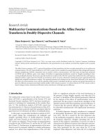
t
1
t
2
t
3
M = 5
t
1
t
2
t
3
M = 5
w
1
w
2
w
3
F
1
= [h
11
g
11
]
∗
F
2
= [h
21
g
21
]
∗
F
3
= [h
31
g
31
]
∗
F
1
= [F
∗
2
| F
∗
3
]
∗
= U
1
Σ
1
0
4×M
V
(1)
1
V
(0)
1
∗
F
2
= [F
∗
1
| F
∗
3
]
∗
= U
2
Σ
2
0
4×M
V
(1)
2
V
(0)
2
∗
F
3
= [F
∗
1
| F
∗
2
]
∗
= U
3
Σ
3
0
4×M
V
(1)
3
V
(0)
3
∗
W
= [w
1
, w
2
, w
3
]
t
R
=
P
r
3
i
=1
w
i
t
i
=
P
r
Wt
Figure 3: Operations of two-way block diagonalization at shared relay via SVD.
Table 3: Sum rate references for proposed schemes.
Scheme DL sum rate UL sum rate
one-way
One-way shared R
DL
shared
(5) R
UL
shared
(6)
One-way shared w/ BS coop. R
DL
coop
(8) R
UL
coop
= R
UL
shared
One-way 802.16j R
DL
nonshared
(17) R
UL
nonshared
(18)
two-way
Two-way DSOF R
DL
DSOF
(26) R
UL
DSOF
(27)
Two - way AS F R
DL
ASF
(35) R
UL
ASF
(33)
Two-way ASOF R
DL
ASOF
(39) R
UL
ASOF
(38)
sectors of interest are positioned at a fixed distance from
their respective base stations and are given a random phase
location within that sector while all other MS’s locations are
chosen uniformly (in distance and phase) within their own
sectors. Figures 4 and 5 show the sum rate performances
versus the MS distance from the BS in the sectors of interest.
Note that the right section of these plots correspond to the
users being located at the cell edge. Several observations
may be made here. The two-way DSOF is superior to all
other schemes as it eliminates interference in both phases
of transmission. The amplify and forward version of this
scheme, that is, ASOF, is also effective at the cell edge where
the average intersector interference is expected to be small.
The nonshared relay performance peaks at an intermediate
location which is expected given the relay positions and the
shared relay surpasses this performance at the cell edge, both
with and without BS coordination. Finally the two-way ASF
is inferior as it lacks any interference management and simply
forwards interference. As expected, the performance here is
similar to the scheme in [7] where a naive AF protocol was
considered. A similar trend holds for the performance in the
UL in Figure 5.
Recall that the decode and forward protocols, such
as the one-way shared relay protocol, amounted to the
minimum rates achieved in two separate phases. For exam-
ple, for the two-way DSOF from (26)wehadR
DL
DSOF
=
(1/3) min{R
DL
1
, R
DL
3
} and Figure 4 did not show the individ-
ual rates R
DL
1
, R
DL
3
but instead ploted the resulting R
DL
DSOF
.
Figure 6 shows a break-down of performance via the two
individual rates for the two-way DSOF scheme. As the MS
moves away from the BS and toward the RS, that is, cell
edge, R
DL
3
increases due to less path loss in the MS-RS link.
After a certain point, for example, 600 m in this figure,
R
DL
3
effectively overtakes R
DL
1
and a bottleneck is created
from the BS-RS link. In summary, this figure shows that the
performance is limited by phase III when the MSs is away
from the cell edge and by phase I when it is near the cell edge.
Therefore one way to improve the performance further is to
12 EURASIP Journal on Advances in Signal Processing
900800700600500400300200100
MS distance from BS (meters)
One-way shared
One-way shared w/ BS coord.
One-way 802.16j
Two-way DSOF
Two -w ay A S F
Two -w ay A S OF
0
1
2
3
4
5
6
7
8
Average DL sum-rate (bps/Hz)
Figure 4: DL sum rate performances versus MS distance from BS.
900800700600500400300200100
MS distance from BS (meters)
One-way shared
One-way shared w/ BS coord.
One-way 802.16j
Two-way DSOF
Two -w ay A S F
Two -w ay A S OF
0
1
2
3
4
5
6
7
8
Average UL sum-rate (bps/Hz)
Figure 5: UL sum rate performance versus MS distance from BS.
increase the relay transmit power when the MS is away from
the cell edge and to increase the BS transmit power when the
MS is near the cell edge.
5.2.2. Cell Edge Performance. The simulations above (par-
ticularly Figure 6) showed that the relay power can have
significant effects on the end performance. While the relay
power was fixed at 37 dBm in those simulations we now
look at the effects of varying relay power when the MSs are
located at the cell edge. Figures 7 and 8 show the sum rate
To w a r d c e l l - e d g e
900800700600500400300200100
MS distance from BS (meters)
R
DL
DSOF
R
DL
1
R
DL
3
1
2
3
4
5
6
7
Average DL sum-rate (bps/Hz)
Figure 6: Performance break down of phases I and III for proposed
two-way DSOF where R
DL
DSOF
= (1/3) min{R
DL
1
, R
DL
3
}.
1050−5−10−15−20−25
Relay power P
r
(dBW)
One-way shared
One-way shared w/ BS coord.
One-way 802.16j
Two-way DSOF
Two -w ay A S F
Two -w ay A S OF
0
1
2
3
4
5
6
7
Average DL sum-rate (bps/Hz)
Figure 7: UL sum rate performance versus average relay transmit
power.
performance as a function of relay transmit power for the
proposed schemes. Increasing the relay transmit power is
expected to improve performance especially when the relay
is employing a strong interference cancelation scheme. The
plots here show again how the two-way DSOF strategy is
superior in this regard, specially at high P
r
. Finally, we note
that this performance gain comes at the expense of higher
EURASIP Journal on Advances in Signal Processing 13
1050−5−10−15−20−25
Relay power P
r
(dBW)
One-way shared
One-way shared w/ BS coord.
One-way 802.16j
Two-way DSOF
Two -w ay A S F
Two -w ay A S OF
0
1
2
3
4
5
6
7
8
9
10
Average UL sum-rate (bps/Hz)
Figure 8: UL sum rate performance versus average relay transmit
power.
transmit complexity, that is, block diagonalization, and the
use of more antennas at the relay compared to the one-way
counterparts.
6. Conclusion
Relay terminals are expected to play an important role in
next generation cellular wireless deployments around the
globe. Such relays are expected to improve link performance
via sophisticated reception and/or transmission techniques
as well as involvement in network interference management
schemes. Previously we had introduced the shared relay
concept, in which a single multi-antenna terminal is shared
between several base stations. In this paper we extended
that concept to incorporate several interference management
schemes in the physical layer at the relays. We considered
both one-way relaying and, the spectrally efficient two-
way relaying categories. For each category we proposed
several relay processing schemes to remove interference
within the network. In some cases we also extended to
include partial or full base station coordination, further
improving the sum rate performances. We conducted link-
level simulations to assess and compare the performance of
the schemes concluding that even simple relay processing
such as zero forcing helps to significantly reduce interference
and improve sum rate. Moreover, sophisticated techniques
such as two-way relaying with block diagonalization surpass
other techniques, specially when the relay is operating at
high transmit power. The improvements here come at the
cost of increased complexity not only at the relay but also
at the receiving terminals by virtue of self-interference. The
performance of the schemes were not optimized here. For
example, given the high transmit asymmetry of the base
stations and mobile stations in the network, power loading
at the relay for dividing the power between transmission
protocols is expected to improve performance. We believe
this to be a promising venue for future work.
Acknowledgment
This work was supported by a gift from Huawei Technolo-
gies, Inc.
References
[1] S. W. Peters and R. W. Heath Jr., “The future of WiMAX:
multihop relaying with IEEE 802.16 j,” IEEE Communications
Magazine, vol. 47, no. 1, pp. 104–111, 2009.
[2] S. Sesia, I. Toufik, and M. Baker, LTE, The UMTS Long Term
Evolution: From Theory to Practice, John Wiley & Sons, New
York, NY, USA, 2009.
[3] D. Ast
´
ely, E. Dahlman, A. Furusk
¨
ar, Y. Jading, M. Lindstr
¨
om,
and S. Parkvall, “LTE: The evolution of mobile broadband,”
IEEE Communications Magazine, vol. 47, no. 4, pp. 44–51,
2009.
[4] E. Dahlman, S. Parkvall, and J. Skold, 3G Evolution: HSPA
and LTE for Mobile Broadband, Academic Press, Edinburg, UK,
2007.
[5] J. Lee, J K. Han, and J. Zhang, “MIMO technologies in
3 G PP LT E a n d LTE - a dv a n ce d ,” EURASIP Journal on Wireless
Communications and Networking, vol. 2009, pp. 1–10, 2009.
[6] S. Parkvall, E. Dahlman, A. Furusk
¨
ar et al., “LTE-Advanced -
Evolving LTE towards IMT-Advanced,” in Proceedings of the
68th Semi-Annual IEEE Vehicular Technology Conference (VTC
’08), pp. 1–5, September 2008.
[7] S. W. Peters, A. Y. Panah, K. T. Truong, and R. W. Heath
Jr., “Relay architectures for 3GPP LTE-advanced,” EURASIP
Journal on Wireless Communications and Networking, vol.
2009, p. 1, 2009.
[8] G. Boudreau, J. Panicker, N. Guo, R. Chang, N. Wang, and
S. Vrzic, “Interference coordination and cancellation for 4G
networks,” IEEE Communications Magazine,vol.47,no.4,pp.
74–81, 2009.
[9] M. Rahman, H. Yanikomeroglu, and W. Wong, “Interference
avoidance with dynamic inter-cell coordination for downlink
LT E s y s te m ,” i n Proceedings of the IEEE Wireless Communica-
tions and Networking Conference (WCNC ’09), April 2009.
[10] J. G. Andrews, W. Choi, and R. W. Heath Jr., “Overcoming
interference in spatial multiplexing mimo cellular networks,”
IEEE Wireless Communications, vol. 14, no. 6, pp. 95–104,
2007.
[11] J. Ellenbeck, C. Hartmann, and L. Berlemann, “Decentralized
inter-cell interference coordination by autonomous spectral
reuse decisions,” in Proceedings of the 14th European Wireless
Conference (EW ’08), pp. 1–7, June 2008.
[12] X. Qiu and K. Chawla, “Intra-cell interference management
for fixed broadband wireless systems,” in Proceedings of the
48th IEEE Vehicular Technology Conference (VTC ’98), pp. 914–
919, May 1998.
[13] G. J. Foschini, K. Karakayali, and R. A. Valenzuela, “Coor-
dinating multiple antenna cellular networks to achieve enor-
mous spectral efficiency,” IEE Proceedings: Communications,
vol. 153, no. 4, pp. 548–555, 2006.
14 EURASIP Journal on Advances in Signal Processing
[14]S.Jing,D.N.C.Tse,J.B.Soriaga,J.Hou,J.E.Smee,and
R. Padovani, “Multicell downlink capacity with coordinated
processing,” EURASIP Journal on Wireless Communications
and Networking, vol. 2008, Article ID 586878, 2008.
[15] M. K. Karakayali, G. J. Foschini, and R. A. Valenzuela, “Net-
work coordination for spectrally efficient communications in
cellular systems,” IEEE Wireless Communications, vol. 13, no.
4, Article ID 1678166, pp. 56–61, 2006.
[16] H. Zhang and H. Dai, “Cochannel interference mitigation
and cooperative processing in downlink multicell multiuser
MIMO networks,” EURASIP Journal on Wireless Communica-
tions and Networking, vol. 2004, no. 2, pp. 222–235, 2004.
[17] J. Ponniah and L L. Xie, “An achievable rate region for
the two-way two-relay channel,” in Proceedings of the IEEE
International Symposium on Information Theory (ISIT ’08),pp.
489–493, July 2008.
[18] M. Chen and A. Yener, “Power allocation for F/TDMA
multiuser two-way relay networks,” IEEE Transactions on
Wireless Communications, vol. 9, no. 2, pp. 546–551, 2010.
[19] C. Es¸li and A. Wittneben, “One-and two-way decode-and-
forward relaying for wireless multiuser MIMO networks,” in
Proceedings of the IEEE Global Telecommunications Conference
(GLOBECOM ’08), pp. 1–6, December 2008.
[20] V. Havary-Nassab, S. Shahbazpanahi, and A. Grami, “Optimal
network beamforming for bi-directional relay networks,” IEEE
Transactions on Signal Processing, vol. 58, no. 3, pp. 1238–1250,
2010.
[21] M. Chen and A. Yener, “Interference management for mul-
tiuser two-way relaying,” in Proceedings of the 42nd Annual
Conference on Information Sciences and Systems (CISS ’08),pp.
246–251, March 2008.
[22] B. Rankov and A. Wittneben, “Achievable rate regions for
the two-way relay channel,” in Proceedings of the IEEE
International Symposium on Information Theory (ISIT ’06),pp.
1668–1672, July 2006.