Factory Automation Part 2 pot
Bạn đang xem bản rút gọn của tài liệu. Xem và tải ngay bản đầy đủ của tài liệu tại đây (1.9 MB, 40 trang )
FactoryAutomation32
erals may vary between < 10 Bytes…> 100 Bytes. Hence, the bandwidth and data rates are of
major importance. The size of the actual data packets depends on the structure of the field
bus system and whether it uses multi-slave or single-slave frames. The network topologies
for wireless solutions range from simple cable replacement point-to-point and point-to-
multipoint connections up to cellular networks with roaming capabilities (production lines,
automated guided vehicles).
Because of the high quantities of devices, the costs for acquisition, installation, commission-
ing, and operation are of major importance on the sensor/actuator level. The sphere of ac-
tion is restricted to small production cells (10 m³…100 m³) with high node densities. The
amount of process data of a single sensor or actuator typically ranges from 1 Byte…10 Bytes.
Hence, lower data rates and bandwidth are sufficient. In its simplest form, wireless solu-
tions operate as cable replacements in point-to-point topology, as well. However, the devel-
opment is focused on high speed wireless sensor/actuator networks (WSANs), supporting
large numbers of devices. These networks are usually arranged in star topology and consist
of wireless sensors/actuators, wireless I/O-concentrators, and a master base station, which
acts as the interface to a super ordinate control system. Due to the increasing latencies, mul-
tihop topologies are currently not considered for WSANs in factory automation.
3. Industrial Wireless Communication Channels
Communication systems have to comply with the stringent requirements concerning reli-
ability, availability, and determinism in order to serve automation applications. In contrast
to that, the quality of a wireless transmission channel experiences random time and fre-
quency variant fluctuations. Hence, the development of wireless communication systems,
for the extreme time critical area of factory automation, is a big challenge.
Industrial environments are often characterised by a high degree of metallic surfaces and
time-varying influences. Besides the movement of the radio systems itself the movements of
materials/tools, rotating machines and persons are responsible for this time variant proper-
ties. In principle industrial radio channels are akin to mobile radio channels. Thus, most
phenomena of industrial radio channels comply with the ones of mobile radio channels.
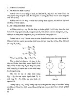
The occurring physical phenomena of transmitted electromagnetic (EM) waves are illus-
trated in figure 2:
Reflexions occur, when EM-waves encounter reflecting objects, whose dimensions
are much larger than the wavelength.
Scattering appears, either when the dimensions of the encountered object are much
smaller than the wavelength of the EM-wave, or when the surface structure is clas-
sified very rough in comparison to the wavelength.
Diffraction occurs when EM-waves encounter sharp edges.
Shadowing is caused by obstacles, which completely block the propagation paths
of EM-waves.
Doppler effects arise, either when there is a relative movement between transmitter
and receiver, or a mobile obstacle in the propagation field reflects, scatters, dif-
fracts, or shadows the EM-wave.
Fig. 2. The classical propagation of electromagnetic waves in a typical industrial
environment.
Because of these wave phenomena a received signal is a composition of different attenuated
and phase shifted versions of the original transmitted signal. Depending on the phase of
these versions, a constructive or destructive overlapping occurs at the receiver. This effect is
called multipath scattering. The absence of a direct non reflected version of the transmitted
signal is typical for industrial radio channels. Does a relative proper motion between the
transmitter and receiver take additionally place, or does the environment change due to
rotating machines or forklift trucks, a shift in frequency based on the doppler effect influ-
ences the transmitted signal. Simultaneously, the path of the signal versions change, result-
ing in a new form of the received signal. Hence, the transmission behaviour of such a radio
channel is time-variant and the signal power experiences high fluctuations.
3.1 Large Scale Fading
The large scale fading results from widespread movements. It depicts the mean signal
power over spatial areas of about 10 wavelengths . Consequently, the local mean values of
the propagation losses (path loss), which depend on the environment (shadowing, reflexion,
diffraction, scattering), are characterised. In this conjunction the log-distance path loss
model (Rappaport, 2002) is often used to describe path losses. The model states, that the
mean received power
decreases logarithmical with the distance between transmitter
and receiver, following
.
is a reference distance near the transmitter, where
the transmit power
is measured with respect to the far-field characteristics of the transmit
antenna. The degree of signal attenuation is expressed by the path loss exponent . A de-
tailed overview of the values of is given in (Rappaport, 2002). In buildings may vary
very much. At frequencies of 400 MHz…4 GHz can take values of
(Hashemi,
1993). In analysis of Rappaport (Rappaport, 2002; Rappaport & Mcgillem, 1989, Rappaport,
WirelessTechnologiesinFactoryAutomation 33
erals may vary between < 10 Bytes…> 100 Bytes. Hence, the bandwidth and data rates are of
major importance. The size of the actual data packets depends on the structure of the field
bus system and whether it uses multi-slave or single-slave frames. The network topologies
for wireless solutions range from simple cable replacement point-to-point and point-to-
multipoint connections up to cellular networks with roaming capabilities (production lines,
automated guided vehicles).
Because of the high quantities of devices, the costs for acquisition, installation, commission-
ing, and operation are of major importance on the sensor/actuator level. The sphere of ac-
tion is restricted to small production cells (10 m³…100 m³) with high node densities. The
amount of process data of a single sensor or actuator typically ranges from 1 Byte…10 Bytes.
Hence, lower data rates and bandwidth are sufficient. In its simplest form, wireless solu-
tions operate as cable replacements in point-to-point topology, as well. However, the devel-
opment is focused on high speed wireless sensor/actuator networks (WSANs), supporting
large numbers of devices. These networks are usually arranged in star topology and consist
of wireless sensors/actuators, wireless I/O-concentrators, and a master base station, which
acts as the interface to a super ordinate control system. Due to the increasing latencies, mul-
tihop topologies are currently not considered for WSANs in factory automation.
3. Industrial Wireless Communication Channels
Communication systems have to comply with the stringent requirements concerning reli-
ability, availability, and determinism in order to serve automation applications. In contrast
to that, the quality of a wireless transmission channel experiences random time and fre-
quency variant fluctuations. Hence, the development of wireless communication systems,
for the extreme time critical area of factory automation, is a big challenge.
Industrial environments are often characterised by a high degree of metallic surfaces and
time-varying influences. Besides the movement of the radio systems itself the movements of
materials/tools, rotating machines and persons are responsible for this time variant proper-
ties. In principle industrial radio channels are akin to mobile radio channels. Thus, most
phenomena of industrial radio channels comply with the ones of mobile radio channels.
The occurring physical phenomena of transmitted electromagnetic (EM) waves are illus-
trated in figure 2:
Reflexions occur, when EM-waves encounter reflecting objects, whose dimensions
are much larger than the wavelength.
Scattering appears, either when the dimensions of the encountered object are much
smaller than the wavelength of the EM-wave, or when the surface structure is clas-
sified very rough in comparison to the wavelength.
Diffraction occurs when EM-waves encounter sharp edges.
Shadowing is caused by obstacles, which completely block the propagation paths
of EM-waves.
Doppler effects arise, either when there is a relative movement between transmitter
and receiver, or a mobile obstacle in the propagation field reflects, scatters, dif-
fracts, or shadows the EM-wave.
Fig. 2. The classical propagation of electromagnetic waves in a typical industrial
environment.
Because of these wave phenomena a received signal is a composition of different attenuated
and phase shifted versions of the original transmitted signal. Depending on the phase of
these versions, a constructive or destructive overlapping occurs at the receiver. This effect is
called multipath scattering. The absence of a direct non reflected version of the transmitted
signal is typical for industrial radio channels. Does a relative proper motion between the
transmitter and receiver take additionally place, or does the environment change due to
rotating machines or forklift trucks, a shift in frequency based on the doppler effect influ-
ences the transmitted signal. Simultaneously, the path of the signal versions change, result-
ing in a new form of the received signal. Hence, the transmission behaviour of such a radio
channel is time-variant and the signal power experiences high fluctuations.
3.1 Large Scale Fading
The large scale fading results from widespread movements. It depicts the mean signal
power over spatial areas of about 10 wavelengths . Consequently, the local mean values of
the propagation losses (path loss), which depend on the environment (shadowing, reflexion,
diffraction, scattering), are characterised. In this conjunction the log-distance path loss
model (Rappaport, 2002) is often used to describe path losses. The model states, that the
mean received power
decreases logarithmical with the distance between transmitter
and receiver, following
.
is a reference distance near the transmitter, where
the transmit power
is measured with respect to the far-field characteristics of the transmit
antenna. The degree of signal attenuation is expressed by the path loss exponent . A de-
tailed overview of the values of is given in (Rappaport, 2002). In buildings may vary
very much. At frequencies of 400 MHz…4 GHz can take values of
(Hashemi,
1993). In analysis of Rappaport (Rappaport, 2002; Rappaport & Mcgillem, 1989, Rappaport,
FactoryAutomation34
1989a), performed in five different factory environments, mean values of
were
measured.
3.2 Small Scale Fading
Small scale fading characterises the fast fluctuations of radio channels over short distances
(fraction ). Primarily, these fast fluctuations of the channel are caused by doppler effects
and multipath scattering. If, for example, a narrow band carrier signal is transmitted, several
randomly organised signal copies arrive at the receiving antenna via different paths. For
every location in a propagation environment, the received signal is the sum of all signal
versions. If the signal versions, which arrive at the receiver, are uncorrelated in phase, the
angles of arrival uniformly distributed, and the signal delay of each path much lower than
the alteration speed of the radio channel, then the behaviour of attenuation can be described
by two complex gaussian processes with mean values of
. If there is no direct
line of sight (NLOS) between transmitter and receiver, the mean value is . In this case
the probability distribution of the absolute amplitude values corresponds to the rayleigh
distribution. If there is a direct line of sight (LOS), the mean value takes the amplitude
value of the signal version, transmitted over the direct path
. The absolute ampli-
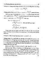
tude values of these channels correspond to the rice distribution. Figure 3 shows a classical
course of the absolute amplitude values of a rayleigh fading channel. The deep fades of up
to 40 dB are characteristic. Analysis in industrial environments (Rappaport & Mcgillem,
1989) showed a dynamic range of 20 dB in signal power, for stationary transmitters and
receivers. When the receiver was moved with a velocity of
, the dynamic range
of the received signal increased to 30 dB…40 dB. If a channel experiences such a deep fade,
several channel errors occur, whose positions show a strong statistical dependence (Paet-
zold, 1999). The occurrence of channel errors temporarily appears in complex blocks.
Fig. 3. The course of amplitudes of a rayleigh fading channel.
Since the rayleigh and the rice models are derived on the assumption of a non modulated
carrier signal, their application is restricted to narrow band signals.
In order to completely characterise a radio channel with respect to the domains of time and
frequency, the time variant impulse response ݄ሺ߬ǡ ݐሻ is an appropriate measure. On the
supposition of a wide sense stationary uncorrelated scattering (WSSUS) channel, the follow-
ing characteristics can be approximated on the basis of Fourier transformations of ݄ሺ߬ǡ ݐሻ and
the computation of first and second order statistics (Bello, 1963):
Delay spread:
The delay spread ߬
௦
describes the mean spread in time of transmitted ߜ-impulse. Scientific
studies showed a delay spread of ߬
௦
ൌ ʹͲǡ ǥ ǡ͵Ͳ݊ݏ at frequencies of 1.3 GHz in industrial
environments (Hashemi, 1993; Rappaport, 1989b). In this conjunction the works of
Haehniche et al. (Haehniche et al., 2000; Haehniche, 2001) are of great practical interest. The
delay spread for the 2.45 GHz ISM frequency band was analysed in different industrial
environments. A mean value of 72 ns and a maximal value of 121 ns were measured. Hoeing
et al. (Hoeing et al., 2006) analysed the delay spread in a production cell with several scatter-
ing obstacles. The transmission distance was 3 m with LOS between transmitter and re-
ceiver. Within the propagation area of interest, fast cyclic movements of machines took
place. Under these conditions a delay spread of ߬
௦
ൌ ͻ݊ݏ was measured, which corre-
sponds to a path difference of about 23.7 m in length.
Coherence bandwidth:
Within a frequency area of ο݂, which is smaller than the coherence bandwidth ܤ
, the
course of ampitudes is expected to be constant. Between the delay spread and the coherence
bandwidth the approximation ߬
௦
ൎ ܤ
ିଵ
is valid. Haehniche et al. analysed the coherence
bandwidth in different industrial environments, as well. Mean values of the coherence
bandwidth ܤ
ൌ ͷǤܯܪݖ were measured for the 2.45 GHz frequency band. In (Scheible,
2007) a coherence bandwidth of up to 10 MHz is reported for this frequency range.
Coherence time:
The coherence time ܶ
is a measure for a radio channels alteration speed.
Doppler spread:
The doppler spread ܦ
ௌ
describes the mean frequency spread of a tranmitted narrow band
carrier signal. Between the coherence time and the doppler spread the approximation
ܶ
ൎ ܦ
ௌ
ିଵ
is valid. The impact of the doppler spread in industrial radio channels may be
enorm. Fast moving or rotating machines may induce high values of the doppler spread.
Hoeing et al. have measured values for ܦ
ௌ
of up to 400 Hz.
On the basis of the presented characteristics, the small scale fading can be further classified
with respect to the variance in time and frequency of a radio channel. If the signal band-
width is much smaller than the coherence bandwidth ܤ
ௌ
ا ܤ
, and the delay spread much
smaller than the symbol duration ߬
௦
ا ܶ
ௌ
, the radio channel is characterised as flat fading
(non frequency selective). Flat fading channels are often referred to as narrow band chan-
nels. If the signal bandwidth is larger than the coherence bandwidth ܤ
ௌ
ب ܤ
, the channel is
frequency selective. In this case the delay ߬ of single paths is larger than the symbol duration
ܶ
ௌ
, what might induce intersymbol interferences (ISI) at the receiver. The time selectivity of a
radio channel may either be described on the basis of the coherence time ܶ
or the doppler
spread ܦ
ௌ
. If the symbol duration is much samller than the coherence time ܶ
ௌ
ا ܶ
, the form
of the transmitted symbol is not altered by the radio channel. These channels are referred as
WirelessTechnologiesinFactoryAutomation 35
1989a), performed in five different factory environments, mean values of
were
measured.
3.2 Small Scale Fading
Small scale fading characterises the fast fluctuations of radio channels over short distances
(fraction ). Primarily, these fast fluctuations of the channel are caused by doppler effects
and multipath scattering. If, for example, a narrow band carrier signal is transmitted, several
randomly organised signal copies arrive at the receiving antenna via different paths. For
every location in a propagation environment, the received signal is the sum of all signal
versions. If the signal versions, which arrive at the receiver, are uncorrelated in phase, the
angles of arrival uniformly distributed, and the signal delay of each path much lower than
the alteration speed of the radio channel, then the behaviour of attenuation can be described
by two complex gaussian processes with mean values of
. If there is no direct
line of sight (NLOS) between transmitter and receiver, the mean value is . In this case
the probability distribution of the absolute amplitude values corresponds to the rayleigh
distribution. If there is a direct line of sight (LOS), the mean value takes the amplitude
value of the signal version, transmitted over the direct path
. The absolute ampli-
tude values of these channels correspond to the rice distribution. Figure 3 shows a classical
course of the absolute amplitude values of a rayleigh fading channel. The deep fades of up
to 40 dB are characteristic. Analysis in industrial environments (Rappaport & Mcgillem,
1989) showed a dynamic range of 20 dB in signal power, for stationary transmitters and
receivers. When the receiver was moved with a velocity of
, the dynamic range
of the received signal increased to 30 dB…40 dB. If a channel experiences such a deep fade,
several channel errors occur, whose positions show a strong statistical dependence (Paet-
zold, 1999). The occurrence of channel errors temporarily appears in complex blocks.
Fig. 3. The course of amplitudes of a rayleigh fading channel.
Since the rayleigh and the rice models are derived on the assumption of a non modulated
carrier signal, their application is restricted to narrow band signals.
In order to completely characterise a radio channel with respect to the domains of time and
frequency, the time variant impulse response ݄
ሺ߬ǡ ݐሻ is an appropriate measure. On the
supposition of a wide sense stationary uncorrelated scattering (WSSUS) channel, the follow-
ing characteristics can be approximated on the basis of Fourier transformations of ݄
ሺ߬ǡ ݐሻ and
the computation of first and second order statistics (Bello, 1963):
Delay spread:
The delay spread ߬
௦
describes the mean spread in time of transmitted ߜ-impulse. Scientific
studies showed a delay spread of ߬
௦
ൌ ʹͲǡ ǥ ǡ͵Ͳ݊ݏ at frequencies of 1.3 GHz in industrial
environments (Hashemi, 1993; Rappaport, 1989b). In this conjunction the works of
Haehniche et al. (Haehniche et al., 2000; Haehniche, 2001) are of great practical interest. The
delay spread for the 2.45 GHz ISM frequency band was analysed in different industrial
environments. A mean value of 72 ns and a maximal value of 121 ns were measured. Hoeing
et al. (Hoeing et al., 2006) analysed the delay spread in a production cell with several scatter-
ing obstacles. The transmission distance was 3 m with LOS between transmitter and re-
ceiver. Within the propagation area of interest, fast cyclic movements of machines took
place. Under these conditions a delay spread of ߬
௦
ൌ ͻ݊ݏ was measured, which corre-
sponds to a path difference of about 23.7 m in length.
Coherence bandwidth:
Within a frequency area of ο݂, which is smaller than the coherence bandwidth ܤ
, the
course of ampitudes is expected to be constant. Between the delay spread and the coherence
bandwidth the approximation ߬
௦
ൎ ܤ
ିଵ
is valid. Haehniche et al. analysed the coherence
bandwidth in different industrial environments, as well. Mean values of the coherence
bandwidth ܤ
ൌ ͷǤܯܪݖ were measured for the 2.45 GHz frequency band. In (Scheible,
2007) a coherence bandwidth of up to 10 MHz is reported for this frequency range.
Coherence time:
The coherence time ܶ
is a measure for a radio channels alteration speed.
Doppler spread:
The doppler spread ܦ
ௌ
describes the mean frequency spread of a tranmitted narrow band
carrier signal. Between the coherence time and the doppler spread the approximation
ܶ
ൎ ܦ
ௌ
ିଵ
is valid. The impact of the doppler spread in industrial radio channels may be
enorm. Fast moving or rotating machines may induce high values of the doppler spread.
Hoeing et al. have measured values for ܦ
ௌ
of up to 400 Hz.
On the basis of the presented characteristics, the small scale fading can be further classified
with respect to the variance in time and frequency of a radio channel. If the signal band-
width is much smaller than the coherence bandwidth ܤ
ௌ
ا ܤ
, and the delay spread much
smaller than the symbol duration ߬
௦
ا ܶ
ௌ
, the radio channel is characterised as flat fading
(non frequency selective). Flat fading channels are often referred to as narrow band chan-
nels. If the signal bandwidth is larger than the coherence bandwidth ܤ
ௌ
ب ܤ
, the channel is
frequency selective. In this case the delay ߬ of single paths is larger than the symbol duration
ܶ
ௌ
, what might induce intersymbol interferences (ISI) at the receiver. The time selectivity of a
radio channel may either be described on the basis of the coherence time ܶ
or the doppler
spread ܦ
ௌ
. If the symbol duration is much samller than the coherence time ܶ
ௌ
ا ܶ
, the form
of the transmitted symbol is not altered by the radio channel. These channels are referred as
FactoryAutomation36
slow fading (non time selective). The opposite is a time selective radio channel referred to as
fast fading.
For a more detailed description of industrial radio channels the authors refer to (Vedral,
2007).
3.3 Performance-Enhancing Strategies
In order to comply with the challenging requirements of automation in the face of the de-
picted fluctuations of industrial radio channels, several performance enhancing strategies
can be applied. It is obvious, that these methods are most effective, when implemented in
the PHY or MAC layers. However, with the given architectures of available transceivers it is
often necessary and only possible to implement appropriate protocols on application layer
(Pellegrini et al., 2006).
Classical methods to improve the performance of radio channels are error detecting (re-
transmissions) or error correcting codes (Liu et al., 1997; Haccoun & Pierre, 1996; Biglieri,
2005), which add further redundancy to the transmitted data. Since these methods are typi-
cally applied to a single channel, their effectiveness mostly depends on the small scale
properties of the channel. Deep fades induce dense blocks of errors, which can be hardly
corrected by error correcting codes. The success of a retransmitted signal depends on the
duration of these deep fading (coherence time). A way to overcome these problems is the
utilisation of diversity techniques. In general diversity describes the transmission of infor-
mation over different channels. The achievable gain depends on the statistical independence
of each transmission channel. With an increasing number of independent transmission
channels the probability increases, that at least one channel is in a good state, and the trans-
mitted signal can be decoded at the receiver. If the error generating processes are completely
uncorrelated, the theoretical minimal error probability is ܲ
ൌ ܲ
for n transmission chan-
nels. Diversity techniques can be applied in the domains of time, frequency, space and an-
gle. Since time diversity implies an increasing latency, its operation in time critical applica-
tions is not suitable. However, by applying spatial or frequency diversity, significant gains
at reasonable costs can be achieved.
Spatial diversity may be applied in different forms. A classification is made for single-user
and multi-user approaches. In the case of single-user, there is only one transmitter and one
receiver, with at least one of which having multiple antennas. In (Diggavi, 2004) it is proven,
that the achievable capacity nearly linearly increases with ܰ ՜ λ, if both transmitter and
receiver are equipped with the same number of antennas ܰ. In its simplest form, multiple
antennas are used at the receiver (SIMO). The single signal versions are combined at the
receiver in order to produce the received signal. Well known combining techniques are
switched combining, equal gain combining or maximum ratio combining (Goldsmith, 2005).
The achievable diversity gain thereby depends on the statistical independence of the re-
ceived signals. On the assumption of a rayleigh fading channel the normalised correlation
coefficients ߩ
ሺ
ߞ
ሻ
of two envelopes can be expressed as a function of antenna separation
(Clarke, 1969) ߩ
ሺ
ߞ
ሻ
ൌ ܬ
ଶ
ȉ ሺʹߨߞሻ. ߞ represents the seperation of two vertical monopole anten-
nas in wavelengths and ܬ
is the Bessel function of first kind and zero order (Zeppernick &
Wysocki, 1999). In (Vedral et al., 2007) practical measurements, in order to evaluate digital
diversity techniques, were performed, based on a multi-transceiver platform, operating in
the 2.45 GHz frequency band. By utilising three receiving antennas at a separation of
4.69 cm a diversity gain of 3.5 dB could be realised in an industrial environment. Bit error
rates (BER) could be reduced by half an order of magnitude compared to a single branch.
The packet error rate (PER) could even be reduced by more than one order of magnitude.
Based on more complex MIMO approaches (Boelcskei, 2006; Paulraj et al., 2004), i.e. applied
in the upcoming standard IEEE 802.11n, performance gains can be further increased. The
capabilities of multi-user approaches, i.e. relaying (Lanemann et al., 2004; Kramer et al.,
2005), for industrial applications has been demonstrated in (Willig, 2008).
A second form of diversity is the transmission of Information over multiple frequencies. The
achievable diversity gains depend on the statistical independence of the single transmission
channels, as well. To obtain statistical independence between two channels their frequency
separation should at least be larger than the actual coherence bandwidth. Following (Clarke,
1969), the normalised correlation coefficient
of two envolpes can be expressed as a
function of frequency seperation
. Thereby describes the se-
peration of the two frequencies and is the maximal delay spread of a current environment.
In narrow band systems frequency diversity is often combined with time diversity in the
form of “frequency hopping spread spectrum” (FHSS). In wide band systems, which use
“orthogonal frequency division multiplex” (OFDM), frequency diversity is often applied on
the basis of channel coding combined with interleaving in the frequency domain. In (Todd
et al., 1992; Corazza et al., 1996) the performance of frequency diversity at frequencies of
1.75 GHz…1.8 GHz has been evaluated in typical office buildings. At an availability of 99 %,
the achieved diversity gains varied between 5 dB 9.6 dB for frequency separations larger
than 5 MHz.
Having in mind the limitation of bandwidth and consumption of energy, spatial diversity is
the more attractive strategy. However, frequency diversity is also considered a suitable
instrument to compensate deep fading. Although it is proven, that optimum combining,
using spatial diversity, may increase the signal to noise plus interference ration (SINR) in
order to mitigate co-channel interferences (Winters, 1984), the application of frequency di-
versity is more effective and less complex.
4. Current Wireless Base Technologies and its Utilisation in Factory
Automation
As already mentioned, most of the industrial wireless solutions use the unlicensed 2.45 GHz
ISM frequency band. This section gives an overview of the regulation and the most impor-
tant technologies operating in this frequency range.
4.1 Regulation for the 2.4 GHz ISM Frequency Band
Within the scope of the regulation 5.138 and 5.150 of the international telecommunication
union, radiocommunication sector (ITU-R), besides others, the frequency range from
2.4 GHz to 2.5 GHz is enabled for industrial, scientific, and medical (ISM) applications. The
European norm EN 300 328 (ETSI 2006) regulates the frequency range from 2.4 GHz to
2.4835 GHz for general utilisation in Europe. The maximal EIRP transmit power is limited to
100 mW. For devices, that do not use the modulation of “frequency hopping spread spec-
trum” (FHSS), the maximal spectral EIRP power density is further limited to 10 mW/MHz.
There are no restrictions concerning the duty cycle of the radios. Depending on the applica-
tion domain and the country, transmit powers above 10 mW have to be registered. In gen-
WirelessTechnologiesinFactoryAutomation 37
slow fading (non time selective). The opposite is a time selective radio channel referred to as
fast fading.
For a more detailed description of industrial radio channels the authors refer to (Vedral,
2007).
3.3 Performance-Enhancing Strategies
In order to comply with the challenging requirements of automation in the face of the de-
picted fluctuations of industrial radio channels, several performance enhancing strategies
can be applied. It is obvious, that these methods are most effective, when implemented in
the PHY or MAC layers. However, with the given architectures of available transceivers it is
often necessary and only possible to implement appropriate protocols on application layer
(Pellegrini et al., 2006).
Classical methods to improve the performance of radio channels are error detecting (re-
transmissions) or error correcting codes (Liu et al., 1997; Haccoun & Pierre, 1996; Biglieri,
2005), which add further redundancy to the transmitted data. Since these methods are typi-
cally applied to a single channel, their effectiveness mostly depends on the small scale
properties of the channel. Deep fades induce dense blocks of errors, which can be hardly
corrected by error correcting codes. The success of a retransmitted signal depends on the
duration of these deep fading (coherence time). A way to overcome these problems is the
utilisation of diversity techniques. In general diversity describes the transmission of infor-
mation over different channels. The achievable gain depends on the statistical independence
of each transmission channel. With an increasing number of independent transmission
channels the probability increases, that at least one channel is in a good state, and the trans-
mitted signal can be decoded at the receiver. If the error generating processes are completely
uncorrelated, the theoretical minimal error probability is ܲ
ൌ ܲ
for n transmission chan-
nels. Diversity techniques can be applied in the domains of time, frequency, space and an-
gle. Since time diversity implies an increasing latency, its operation in time critical applica-
tions is not suitable. However, by applying spatial or frequency diversity, significant gains
at reasonable costs can be achieved.
Spatial diversity may be applied in different forms. A classification is made for single-user
and multi-user approaches. In the case of single-user, there is only one transmitter and one
receiver, with at least one of which having multiple antennas. In (Diggavi, 2004) it is proven,
that the achievable capacity nearly linearly increases with ܰ ՜ λ, if both transmitter and
receiver are equipped with the same number of antennas ܰ. In its simplest form, multiple
antennas are used at the receiver (SIMO). The single signal versions are combined at the
receiver in order to produce the received signal. Well known combining techniques are
switched combining, equal gain combining or maximum ratio combining (Goldsmith, 2005).
The achievable diversity gain thereby depends on the statistical independence of the re-
ceived signals. On the assumption of a rayleigh fading channel the normalised correlation
coefficients ߩ
ሺ
ߞ
ሻ
of two envelopes can be expressed as a function of antenna separation
(Clarke, 1969) ߩ
ሺ
ߞ
ሻ
ൌ ܬ
ଶ
ȉ ሺʹߨߞሻ. ߞ represents the seperation of two vertical monopole anten-
nas in wavelengths and ܬ
is the Bessel function of first kind and zero order (Zeppernick &
Wysocki, 1999). In (Vedral et al., 2007) practical measurements, in order to evaluate digital
diversity techniques, were performed, based on a multi-transceiver platform, operating in
the 2.45 GHz frequency band. By utilising three receiving antennas at a separation of
4.69 cm a diversity gain of 3.5 dB could be realised in an industrial environment. Bit error
rates (BER) could be reduced by half an order of magnitude compared to a single branch.
The packet error rate (PER) could even be reduced by more than one order of magnitude.
Based on more complex MIMO approaches (Boelcskei, 2006; Paulraj et al., 2004), i.e. applied
in the upcoming standard IEEE 802.11n, performance gains can be further increased. The
capabilities of multi-user approaches, i.e. relaying (Lanemann et al., 2004; Kramer et al.,
2005), for industrial applications has been demonstrated in (Willig, 2008).
A second form of diversity is the transmission of Information over multiple frequencies. The
achievable diversity gains depend on the statistical independence of the single transmission
channels, as well. To obtain statistical independence between two channels their frequency
separation should at least be larger than the actual coherence bandwidth. Following (Clarke,
1969), the normalised correlation coefficient
of two envolpes can be expressed as a
function of frequency seperation
. Thereby describes the se-
peration of the two frequencies and is the maximal delay spread of a current environment.
In narrow band systems frequency diversity is often combined with time diversity in the
form of “frequency hopping spread spectrum” (FHSS). In wide band systems, which use
“orthogonal frequency division multiplex” (OFDM), frequency diversity is often applied on
the basis of channel coding combined with interleaving in the frequency domain. In (Todd
et al., 1992; Corazza et al., 1996) the performance of frequency diversity at frequencies of
1.75 GHz…1.8 GHz has been evaluated in typical office buildings. At an availability of 99 %,
the achieved diversity gains varied between 5 dB 9.6 dB for frequency separations larger
than 5 MHz.
Having in mind the limitation of bandwidth and consumption of energy, spatial diversity is
the more attractive strategy. However, frequency diversity is also considered a suitable
instrument to compensate deep fading. Although it is proven, that optimum combining,
using spatial diversity, may increase the signal to noise plus interference ration (SINR) in
order to mitigate co-channel interferences (Winters, 1984), the application of frequency di-
versity is more effective and less complex.
4. Current Wireless Base Technologies and its Utilisation in Factory
Automation
As already mentioned, most of the industrial wireless solutions use the unlicensed 2.45 GHz
ISM frequency band. This section gives an overview of the regulation and the most impor-
tant technologies operating in this frequency range.
4.1 Regulation for the 2.4 GHz ISM Frequency Band
Within the scope of the regulation 5.138 and 5.150 of the international telecommunication
union, radiocommunication sector (ITU-R), besides others, the frequency range from
2.4 GHz to 2.5 GHz is enabled for industrial, scientific, and medical (ISM) applications. The
European norm EN 300 328 (ETSI 2006) regulates the frequency range from 2.4 GHz to
2.4835 GHz for general utilisation in Europe. The maximal EIRP transmit power is limited to
100 mW. For devices, that do not use the modulation of “frequency hopping spread spec-
trum” (FHSS), the maximal spectral EIRP power density is further limited to 10 mW/MHz.
There are no restrictions concerning the duty cycle of the radios. Depending on the applica-
tion domain and the country, transmit powers above 10 mW have to be registered. In gen-
FactoryAutomation38
eral, there are country specific limitations to the utilisation of the 2.45 GHz ISM band (i.e.
Spain and France).
In North America, the utilisation of unlicensed frequency bands is ruled by the Federal
Communications Commission (FCC 2007) in the document CFR 47, Part 15. The maximal
transmit power for the 2.45 GHz band is limited to 1 W for systems using FHSS over more
than 75 frequency channels. For systems with less than 75 channels, the maximal transmit
power is limited to 125 mW. In addition to that, a spectral power density of 8 dBm/3 kHz
must not be exceeded.
4.2 Wireless Local Area Networks - IEEE 802.11
The most popular radio technologies operating within the 2.45 GHz band are compliant to
the standards of IEEE 802.11b and IEEE 802.11g. Both standards specify 13 channels with
spacing of 5 MHz for Europe and 11 for North America.
Fig. 4. IEEE 802.11 defines 13 channels for Europe and 14 Channels for North America.
With a transmit bandwidth of about 20 MHz, three non overlapping channels with a spacing
of 30 MHz are available. The maximal transmit power is limited to 100 mW.
IEEE 802.11b supports data rates of 1 Mbps…11 Mbps. According to the selected data rates,
the modulations of “differential binary phase shift keying“ (DBPSK), „differential quadra-
ture phase shift keying“ (DQPSK) or, „complementary code keying“ (CCK) are used. “Direct
sequence spread spectrum” (DSSS) is used as a spreading technique. The amendment of
IEEE 802.11g is an extension and supports data rates of up to 54 Mbps by introducing “or-
thogonal frequency division multiplex” (OFDM) with 52 sub-carriers as a spreading tech-
nique. These sub-carriers are either modulated using „binary phase shift keying“ (BPSK),
„quadrature phase shift keying (QPSK), „16- or 64-quadrature amplitude modulation“ (16-
QAM, 64-QAM) depending on the selected data rates. Furthermore this standard supports
forward error correction (FEC) with coding rates of 1/2, 2/3, or 3/4. As the channel access
method, both standards use “carrier sense multiple access/collision avoidance”, which is
based on a “clear channel assessment” (CCA) module. Prior to any transmission, the CCA
module validates the occupation of the medium. If the medium is classified “busy”, the
transmit operation is interrupted for a pseudo random period of time and the channel is
validated again. A prioritised medium access, comprising eight priority levels, was intro-
duced by the extension of IEEE 802.11e. In order to classify the medium, three modes are
specified and one of them must at least be supported. In mode 1 the medium is considered
busy, as soon as the detected energy is above a predefined threshold. In mode 2 the medium
is considered busy, if an IEEE 802.11 modulated signal is detected. In mode 3 the medium is
considered busy, if an IEEE 802.11 modulated signal is detected and its energy is above a
predefined threshold. In general, the end-user has no access to the configuration of the CCA
mode.
In automation applications IEEE 802.11 is recommended by the PROFIBUS & PROFINET
International (PI) as a wireless communication system for connecting PLCs and decentral-
ised peripherals. With adapted IEEE 802.11 systems, PROFINET-I/O communications with
update times of up to 8 ms can be served. Common use cases are forklift trucks and auto-
mated guided vehicles. In mobile scenarios the transition from one cell to another (roaming)
is extremely critical. Currently, roaming times of < 50 % can be realised.
The next Amendment of the task group IEEE 802.11n is shortly before being published. This
standard specifies either channels with 20 MHz bandwidth and 56 OFDM sub-carriers and
channels with 40 MHz bandwidth and 112 sub-carriers within the frequency bands of
2.45 GHz and 5 GHz. By applying performance enhancing techniques like “MIMO”, “Chan-
nel Bonding“, “Frame Aggregation“, “Spatial Multiplexing“, and “Beam forming“, data
rates of 300 Mbps and beyond can be achieved. At the moment the draft standard, revision
8, is available (LAN/MAN Standards Committee of the IEEE Computer Society, 2008). The
release of the final standard is expected in late 2009. Similar to the standards IEEE 802.11b
and IEEE 802.11g a fast market penetration can be expected for the standard IEEE 802.11n,
as well.
4.3 Bluetooth – IEEE 802.15.1
The latest specification of Bluetooth version 3.0 (Bluetooth Special Interest Group – SIG,
2009) was published in 2009. The PHY and MAC layer of the Bluetooth version 1.1 are pub-
lished as the standard IEEE 802.15.1, as well. In its classical form 79 channels, with a spacing
of 1 MHz, are specified in the range of 2.402 GHz…2.480 GHz. The radio signals are modu-
lated using “Gaussian frequency shift keying“ (GFSK, 1 Mbps), “π/4 differential quaternary
phase shift keying“ (π/4-DQPSK, 2 Mbps), or “8-ary differential encoded phase shift key-
ing“ (8DPSK, 3 Mbps). Bluetooth uses “Time Division Multiple Access“ (TDMA) as the
channel access method and FHSS for spreading. Three device classes with transmit powers
of 1 mW, 2.5 mW and 100 mW are defined.
Bluetooth networks, called piconets, are formed in star topology. A piconet consists of a
master and up to seven active slaves. In order to communicate, timeslots with a length of
625 µs are predefined. The specification defines synchronous connections (SCO) for the
transmission of i.e. speech and asynchronous connections (ACL) for data transmission.
Depending on the type, data packets occupy one to five timeslots and use “automated re-
peat requests” (ARQ) or FEC as channel coding. In each timeslot, or at leas after the trans-
mission of a data packet, a change in frequency is performed respectively.
Fig. 5. IEEE 802.15.1 defines 79 Channels within the 2.45 GHz ISM Band.
In avoidance of coexistence problems, the standard supports an “adaptive power control”
(APC) and “adaptive frequency hopping“ (AFH). When using AFH, frequency channels
WirelessTechnologiesinFactoryAutomation 39
eral, there are country specific limitations to the utilisation of the 2.45 GHz ISM band (i.e.
Spain and France).
In North America, the utilisation of unlicensed frequency bands is ruled by the Federal
Communications Commission (FCC 2007) in the document CFR 47, Part 15. The maximal
transmit power for the 2.45 GHz band is limited to 1 W for systems using FHSS over more
than 75 frequency channels. For systems with less than 75 channels, the maximal transmit
power is limited to 125 mW. In addition to that, a spectral power density of 8 dBm/3 kHz
must not be exceeded.
4.2 Wireless Local Area Networks - IEEE 802.11
The most popular radio technologies operating within the 2.45 GHz band are compliant to
the standards of IEEE 802.11b and IEEE 802.11g. Both standards specify 13 channels with
spacing of 5 MHz for Europe and 11 for North America.
Fig. 4. IEEE 802.11 defines 13 channels for Europe and 14 Channels for North America.
With a transmit bandwidth of about 20 MHz, three non overlapping channels with a spacing
of 30 MHz are available. The maximal transmit power is limited to 100 mW.
IEEE 802.11b supports data rates of 1 Mbps…11 Mbps. According to the selected data rates,
the modulations of “differential binary phase shift keying“ (DBPSK), „differential quadra-
ture phase shift keying“ (DQPSK) or, „complementary code keying“ (CCK) are used. “Direct
sequence spread spectrum” (DSSS) is used as a spreading technique. The amendment of
IEEE 802.11g is an extension and supports data rates of up to 54 Mbps by introducing “or-
thogonal frequency division multiplex” (OFDM) with 52 sub-carriers as a spreading tech-
nique. These sub-carriers are either modulated using „binary phase shift keying“ (BPSK),
„quadrature phase shift keying (QPSK), „16- or 64-quadrature amplitude modulation“ (16-
QAM, 64-QAM) depending on the selected data rates. Furthermore this standard supports
forward error correction (FEC) with coding rates of 1/2, 2/3, or 3/4. As the channel access
method, both standards use “carrier sense multiple access/collision avoidance”, which is
based on a “clear channel assessment” (CCA) module. Prior to any transmission, the CCA
module validates the occupation of the medium. If the medium is classified “busy”, the
transmit operation is interrupted for a pseudo random period of time and the channel is
validated again. A prioritised medium access, comprising eight priority levels, was intro-
duced by the extension of IEEE 802.11e. In order to classify the medium, three modes are
specified and one of them must at least be supported. In mode 1 the medium is considered
busy, as soon as the detected energy is above a predefined threshold. In mode 2 the medium
is considered busy, if an IEEE 802.11 modulated signal is detected. In mode 3 the medium is
considered busy, if an IEEE 802.11 modulated signal is detected and its energy is above a
predefined threshold. In general, the end-user has no access to the configuration of the CCA
mode.
In automation applications IEEE 802.11 is recommended by the PROFIBUS & PROFINET
International (PI) as a wireless communication system for connecting PLCs and decentral-
ised peripherals. With adapted IEEE 802.11 systems, PROFINET-I/O communications with
update times of up to 8 ms can be served. Common use cases are forklift trucks and auto-
mated guided vehicles. In mobile scenarios the transition from one cell to another (roaming)
is extremely critical. Currently, roaming times of < 50 % can be realised.
The next Amendment of the task group IEEE 802.11n is shortly before being published. This
standard specifies either channels with 20 MHz bandwidth and 56 OFDM sub-carriers and
channels with 40 MHz bandwidth and 112 sub-carriers within the frequency bands of
2.45 GHz and 5 GHz. By applying performance enhancing techniques like “MIMO”, “Chan-
nel Bonding“, “Frame Aggregation“, “Spatial Multiplexing“, and “Beam forming“, data
rates of 300 Mbps and beyond can be achieved. At the moment the draft standard, revision
8, is available (LAN/MAN Standards Committee of the IEEE Computer Society, 2008). The
release of the final standard is expected in late 2009. Similar to the standards IEEE 802.11b
and IEEE 802.11g a fast market penetration can be expected for the standard IEEE 802.11n,
as well.
4.3 Bluetooth – IEEE 802.15.1
The latest specification of Bluetooth version 3.0 (Bluetooth Special Interest Group – SIG,
2009) was published in 2009. The PHY and MAC layer of the Bluetooth version 1.1 are pub-
lished as the standard IEEE 802.15.1, as well. In its classical form 79 channels, with a spacing
of 1 MHz, are specified in the range of 2.402 GHz…2.480 GHz. The radio signals are modu-
lated using “Gaussian frequency shift keying“ (GFSK, 1 Mbps), “π/4 differential quaternary
phase shift keying“ (π/4-DQPSK, 2 Mbps), or “8-ary differential encoded phase shift key-
ing“ (8DPSK, 3 Mbps). Bluetooth uses “Time Division Multiple Access“ (TDMA) as the
channel access method and FHSS for spreading. Three device classes with transmit powers
of 1 mW, 2.5 mW and 100 mW are defined.
Bluetooth networks, called piconets, are formed in star topology. A piconet consists of a
master and up to seven active slaves. In order to communicate, timeslots with a length of
625 µs are predefined. The specification defines synchronous connections (SCO) for the
transmission of i.e. speech and asynchronous connections (ACL) for data transmission.
Depending on the type, data packets occupy one to five timeslots and use “automated re-
peat requests” (ARQ) or FEC as channel coding. In each timeslot, or at leas after the trans-
mission of a data packet, a change in frequency is performed respectively.
Fig. 5. IEEE 802.15.1 defines 79 Channels within the 2.45 GHz ISM Band.
In avoidance of coexistence problems, the standard supports an “adaptive power control”
(APC) and “adaptive frequency hopping“ (AFH). When using AFH, frequency channels
FactoryAutomation40
occupied by foreign radios are detected and excluded from the hopping scheme. With com-
mon Bluetooth transceiver chips a channel is classified busy, when the occupation is higher
than 15 %. The adaption of the hopping scheme depends on the implementation and may
take up to several seconds. In addition to the adaptive channel classification, frequency
channels can be excluded of the hopping scheme manually, in order to avoid frequencies
known to be in use by other radios. At least 20 channels have to be used. By doing so, a
frequency separation to two coexisting IEEE 802.11 radios can be administered. Solely, the
connection setup uses all frequencies. However, some vendors developed standard compli-
ant solutions, which prevent interferences during the connection setup.
Bluetooth is applicable at control as well as sensor/actuator level. With respect to ABBs
“Wireless interface for sensors and actuators” (WISA), the PROFIBUS & PROFINET Interna-
tional (PI) actually considers the PHY layer of Bluetooth as the basis for “Wireless Sen-
sor/Actor Networks” (WSANs). A standard shall be published in 2010. A WISA network
consists of a base station and up to 120 wireless I/O-concentrators and sensors/actuators in
a star topology. The base station acts as the network coordinator and gateway to a super
ordinate control system. The I/O-concentrators and sensors/actuators use IEEE 802.15.1
standard compliant transceivers. The base station consists of a special multi-transceiver
architecture and thus able to serve multiple devices in parallel. The update time of 120 sen-
sors is typically below 20 ms.
In version 3.0 of Bluetooth, the support of IEEE 802.11 as an “Alternate MAC PHY” (AMP) is
introduced. In addition to that the “Bluetooth Low Energy” specification is to be published
in late 2009. First transceivers for both technologies shall be available in 2010.
4.4 IEEE 802.15.4
The standard IEEE 802.15.4 specifies 16 channels with a separation of 5 MHz for the
2.45 GHz ISM band. With DSSS as spreading and “offset quadrature phase shift keying” (O-
QPSK) as modulation, data rates of 250 kbps are supported. The standard limits the transmit
power to 1 mW. However, the regulations allow the operation at transmit powers of up to
10 mW.
As channel access method CSMA/CA corresponding to IEEE 802.11 is utilised. Optionally,
the standard supports a synchronised data communication in superframes of durations from
15 ms to 246 s. Each superframe consists of a “contention access period” (CAP) and a “con-
tention free period” (CFP). During the CAP, devices willing to transmit, concurrently access
the medium via CSMA/CA. The CFP consists of guaranteed timeslots and gives exclusive
access to medium for higher prioritised transmissions. The standard was designed for low
power industrial “wireless personal area networks” with low data rates.
Fig. 6. IEEE 802.15.4 defines 16 Channels within the 2.45 GHz ISM Band.
The technology is wide spread in combination with the higher layers specified by ZigBee.
ZigBee supports the operation of large multihop networks and addresses domains like
home- and building automation, smart metering, and health care.
Within the scope of the HART 7 specifications, the first wireless standard for process auto-
mation, WirelessHART, was published in 2007. WirelessHART is based on the PHY layer of
IEEE 802.15.4 and uses the “Time Synchronized Mesh Protocol“ (TSMP) for channel access.
In order to improve reliability, it is designed to support large multihop networks in full
mesh topologies with a high degree of redundant paths. In avoidance of coexistence prob-
lems the standard changes frequencies at a rate of 10 ms. Optionally, a channel black list can
be used to avoid frequencies currently in use. First products are successfully in use since late
2008.
At the moment “the International Society of Automation” (ISA) is shortly before publishing
a second standard for the process automation, ISA 100.11a (ISA, 2009), based on the PHY
layer of IEEE 802.15.4.
In the domain of factory automation a few proprietary solutions for the transmission of
sensor data based on IEEE 802.15.4 are available.
Right now the task group of IEEE 802.15.4e is working on MAC layer extensions. In order to
improve the support of time critical industrial applications, shorter transmit times, im-
proved TDMA techniques and frequency hopping are evaluated. In the long run the exten-
sions of IEEE 802.15.4e shall enable the standard to better support applications in factory
automation.
4.5 Coexistence in the 2.4 GHz ISM Frequency Band
With the fast pace growth of wireless solutions, operating in the 2.45 GHz ISM band, in
automation as well as the IT, the end-users demand for a good coexistence of the devices is
getting obvious. In this respect a technologies coexistence properties depend on several
parameters, like the transmit power, signal bandwidth, channel access methods, and duty-
cycle, which often are vendor specific.
In IEEE 802.15.2 (LAN/MAN Standards Committee of the IEEE Computer Society, 2003)
coexistence is defined as “a systems ability to perform a task in a shared medium, while
other systems perform their tasks, complying with the same or a different set of rules”. In a
shared medium the main source of error is caused by interferences. Interferences appear,
when signals overlay in the domains of time, frequency, and space. For the domain of fre-
quency the IEEE Unapproved Draft Std P1900.2/D2.22 (LAN/MAN Standards Committee
of the IEEE Computer Society, 2007b) further subdivides interferences into “In-Band“, con-
sisting of “Co-Channel-“ and “Adjacent Channel- Interference“, and “Out of Band“, consist-
ing of “Band Edge-“ und “Far out of Band Interference“. The most common form of appear-
ance are “Co-Channel” interferences, which occur, when more than one system operates on
the same frequency.
WirelessTechnologiesinFactoryAutomation 41
occupied by foreign radios are detected and excluded from the hopping scheme. With com-
mon Bluetooth transceiver chips a channel is classified busy, when the occupation is higher
than 15 %. The adaption of the hopping scheme depends on the implementation and may
take up to several seconds. In addition to the adaptive channel classification, frequency
channels can be excluded of the hopping scheme manually, in order to avoid frequencies
known to be in use by other radios. At least 20 channels have to be used. By doing so, a
frequency separation to two coexisting IEEE 802.11 radios can be administered. Solely, the
connection setup uses all frequencies. However, some vendors developed standard compli-
ant solutions, which prevent interferences during the connection setup.
Bluetooth is applicable at control as well as sensor/actuator level. With respect to ABBs
“Wireless interface for sensors and actuators” (WISA), the PROFIBUS & PROFINET Interna-
tional (PI) actually considers the PHY layer of Bluetooth as the basis for “Wireless Sen-
sor/Actor Networks” (WSANs). A standard shall be published in 2010. A WISA network
consists of a base station and up to 120 wireless I/O-concentrators and sensors/actuators in
a star topology. The base station acts as the network coordinator and gateway to a super
ordinate control system. The I/O-concentrators and sensors/actuators use IEEE 802.15.1
standard compliant transceivers. The base station consists of a special multi-transceiver
architecture and thus able to serve multiple devices in parallel. The update time of 120 sen-
sors is typically below 20 ms.
In version 3.0 of Bluetooth, the support of IEEE 802.11 as an “Alternate MAC PHY” (AMP) is
introduced. In addition to that the “Bluetooth Low Energy” specification is to be published
in late 2009. First transceivers for both technologies shall be available in 2010.
4.4 IEEE 802.15.4
The standard IEEE 802.15.4 specifies 16 channels with a separation of 5 MHz for the
2.45 GHz ISM band. With DSSS as spreading and “offset quadrature phase shift keying” (O-
QPSK) as modulation, data rates of 250 kbps are supported. The standard limits the transmit
power to 1 mW. However, the regulations allow the operation at transmit powers of up to
10 mW.
As channel access method CSMA/CA corresponding to IEEE 802.11 is utilised. Optionally,
the standard supports a synchronised data communication in superframes of durations from
15 ms to 246 s. Each superframe consists of a “contention access period” (CAP) and a “con-
tention free period” (CFP). During the CAP, devices willing to transmit, concurrently access
the medium via CSMA/CA. The CFP consists of guaranteed timeslots and gives exclusive
access to medium for higher prioritised transmissions. The standard was designed for low
power industrial “wireless personal area networks” with low data rates.
Fig. 6. IEEE 802.15.4 defines 16 Channels within the 2.45 GHz ISM Band.
The technology is wide spread in combination with the higher layers specified by ZigBee.
ZigBee supports the operation of large multihop networks and addresses domains like
home- and building automation, smart metering, and health care.
Within the scope of the HART 7 specifications, the first wireless standard for process auto-
mation, WirelessHART, was published in 2007. WirelessHART is based on the PHY layer of
IEEE 802.15.4 and uses the “Time Synchronized Mesh Protocol“ (TSMP) for channel access.
In order to improve reliability, it is designed to support large multihop networks in full
mesh topologies with a high degree of redundant paths. In avoidance of coexistence prob-
lems the standard changes frequencies at a rate of 10 ms. Optionally, a channel black list can
be used to avoid frequencies currently in use. First products are successfully in use since late
2008.
At the moment “the International Society of Automation” (ISA) is shortly before publishing
a second standard for the process automation, ISA 100.11a (ISA, 2009), based on the PHY
layer of IEEE 802.15.4.
In the domain of factory automation a few proprietary solutions for the transmission of
sensor data based on IEEE 802.15.4 are available.
Right now the task group of IEEE 802.15.4e is working on MAC layer extensions. In order to
improve the support of time critical industrial applications, shorter transmit times, im-
proved TDMA techniques and frequency hopping are evaluated. In the long run the exten-
sions of IEEE 802.15.4e shall enable the standard to better support applications in factory
automation.
4.5 Coexistence in the 2.4 GHz ISM Frequency Band
With the fast pace growth of wireless solutions, operating in the 2.45 GHz ISM band, in
automation as well as the IT, the end-users demand for a good coexistence of the devices is
getting obvious. In this respect a technologies coexistence properties depend on several
parameters, like the transmit power, signal bandwidth, channel access methods, and duty-
cycle, which often are vendor specific.
In IEEE 802.15.2 (LAN/MAN Standards Committee of the IEEE Computer Society, 2003)
coexistence is defined as “a systems ability to perform a task in a shared medium, while
other systems perform their tasks, complying with the same or a different set of rules”. In a
shared medium the main source of error is caused by interferences. Interferences appear,
when signals overlay in the domains of time, frequency, and space. For the domain of fre-
quency the IEEE Unapproved Draft Std P1900.2/D2.22 (LAN/MAN Standards Committee
of the IEEE Computer Society, 2007b) further subdivides interferences into “In-Band“, con-
sisting of “Co-Channel-“ and “Adjacent Channel- Interference“, and “Out of Band“, consist-
ing of “Band Edge-“ und “Far out of Band Interference“. The most common form of appear-
ance are “Co-Channel” interferences, which occur, when more than one system operates on
the same frequency.
FactoryAutomation42
Fig. 7. Types of Interference defined by IEEE P1900.2/D2.22.
The domain of time is determined by the channel occupation in time, the duty cycle, of coex-
isting systems. The probability of signal interferences increases with the utilisation of the
medium in time. The spatial domain is defined by the transmit power, the distance between
the systems (Antennas), and the resulting “signal to interference plus noise ratio” (SINR). If
the SINR is too low, a signal cannot be detected correctly at the receiver.
Besides these physical properties of interferences, channel access methods have a strong
impact on the coexistence of radios. Typically, radio systems operating in the 2.45 GHz ISM
band use either TDMA, CSMA/CA, or a mixture of both as access methods. TDMA subdi-
vides the medium into timeslots, which are reserved for exclusive access to the medium.
That way, TDMA systems support a deterministic behaviour in time and a good coexistence
within the same network. In order to avoid interferences to foreign networks, TDMA is
often used in combination with FHSS, additionally allowing to black list frequencies already
in use by other systems (i.e. Bluetooth). When using CSMA/CA, the state of the medium is
validated before any transmission of data and only performed, if the medium is classified
idle. The validation of the medium is either based on an energy threshold, the detection of a
valid carrier, or a mixture of both. On the one hand CSMA/CA is able to avoid interfer-
ences within the same or foreign networks. On the other hand CSMA/CA is vulnerable to
jamming attacks and some kind of unnecessary interferences. Depending on the implemen-
tation, the following types of interferences may occur, when using CSMA/CA:
Type-1: A weak signal, that would not induce interferences at the receiver, is de-
tected at the transmitter, causes the medium to be classified busy, and thus delays
the transmission (“Exposed Terminal Problem“).
Type-2: Interferences caused by multiple radios that access the medium at the same
time.
Type-3: The source of interference is out of the detection range of the transmitter,
but causes interferences at the receiver (“Hidden Terminal Problem”).
There are several strategies to mitigate these interferences within the same network of op-
eration (Tsertou & Laurenson, 2008; Zhang et al., 2008). However, interferences with foreign
networks may still appear.
How far interferences actually influence the coexistence properties of a system, always de-
pends on the tasks to be performed. Usually, an underlying (wireless) communication sys-
tem has a temporal reserve with respect to an application, in order to perform channel cod-
ing and retransmissions. If this reserve gets exhausted, the communication system cannot
longer serve the application. It is obvious, that with increasing temporal requirements of an
Typesof
Interferencef
Outof
Band
InBand
Co‐Channel
Adjacent
Channel
Edge of
Band
Far outof
Band
application, the reserve of the communication system decreases and interferences result in
application errors faster. Analytical as well as practical studies about the coexistence within
the 2.45 GHz ISM band have been subject to several publications. For detailed information
on this topic it is referred to (Arumugm et al., 2003; Chiasserini & Rao, 2003; Howitt &
Gutierrez, 2003).
The previous descriptions stated the richness of technologies and applications operating in
the 2.45 GHz ISM band. Thus, a coexisting operation of different wireless solutions is hardly
avoidable. But it is very demanding to consider all parameter of relevance for the different
domains of applications, when determining the properties of coexistence of radio technolo-
gies. In addition to that, comprehensive studies on the coexistence of new technologies, like
IEEE 802.11n, WirelessHART, ISA 100.11a, and Bluetooth Low Energy have not been per-
formed, yet.
Category Class Application Description
Safety 0 Emergency action (always critical)
Control
1 Closed loop regulatory control (often critical)
2 Closed loop supervisory control (usually non-critical)
3 Open loop control (human in the loop)
Monitoring
4 Alerting
Short-term operational conse-
quences (e.g. event-based
maintenance)
5
Logging and download-
ing/uploading
No immediate operational
consequence (e.g., history
collection, sequence-of-events,
preventive maintenance)
Table 1. Application classes of ISA-SP100.
For that reason, a general process to establish a coexistence management for end user is
described in (VDI, 2008). In relation to the application classes defined in (ISA, 2006), it is
recommended to assign priorities to the different wireless solutions. The intensity for the
frequency management shall be correlated to the assigned priority classes. The process
comprises the whole plant location and shall include all persons responsible for planning,
installing, and commissioning of wireless devices. Wireless applications either in automa-
tion, logistic, or IT have to be considered. The coexistence management is a cyclic process
which comprises all stages of stock taking, planning, installation, commissioning, mainte-
nance, operation, and documentation of wireless applications at a location. It is further rec-
ommended to involve qualified service providers and own personnel at early phases, in
avoidance of malfunctions in the long run.
5. Upcoming Wireless Base Technologies
The development of wireless technologies and extended standards is fast pacing. Especially
the progress with respect to ultra wideband (UWB) represents a great potential, to open up
new domains of applications in factory automation. First efforts for a standardisation of
UWB technologies were initiated by the IEEE 802.15 WPAN High Rate Alternative PHY
Task Group 3a (TG3a), founded in 2001. The task groups aim was to develop a high speed
WirelessTechnologiesinFactoryAutomation 43
Fig. 7. Types of Interference defined by IEEE P1900.2/D2.22.
The domain of time is determined by the channel occupation in time, the duty cycle, of coex-
isting systems. The probability of signal interferences increases with the utilisation of the
medium in time. The spatial domain is defined by the transmit power, the distance between
the systems (Antennas), and the resulting “signal to interference plus noise ratio” (SINR). If
the SINR is too low, a signal cannot be detected correctly at the receiver.
Besides these physical properties of interferences, channel access methods have a strong
impact on the coexistence of radios. Typically, radio systems operating in the 2.45 GHz ISM
band use either TDMA, CSMA/CA, or a mixture of both as access methods. TDMA subdi-
vides the medium into timeslots, which are reserved for exclusive access to the medium.
That way, TDMA systems support a deterministic behaviour in time and a good coexistence
within the same network. In order to avoid interferences to foreign networks, TDMA is
often used in combination with FHSS, additionally allowing to black list frequencies already
in use by other systems (i.e. Bluetooth). When using CSMA/CA, the state of the medium is
validated before any transmission of data and only performed, if the medium is classified
idle. The validation of the medium is either based on an energy threshold, the detection of a
valid carrier, or a mixture of both. On the one hand CSMA/CA is able to avoid interfer-
ences within the same or foreign networks. On the other hand CSMA/CA is vulnerable to
jamming attacks and some kind of unnecessary interferences. Depending on the implemen-
tation, the following types of interferences may occur, when using CSMA/CA:
Type-1: A weak signal, that would not induce interferences at the receiver, is de-
tected at the transmitter, causes the medium to be classified busy, and thus delays
the transmission (“Exposed Terminal Problem“).
Type-2: Interferences caused by multiple radios that access the medium at the same
time.
Type-3: The source of interference is out of the detection range of the transmitter,
but causes interferences at the receiver (“Hidden Terminal Problem”).
There are several strategies to mitigate these interferences within the same network of op-
eration (Tsertou & Laurenson, 2008; Zhang et al., 2008). However, interferences with foreign
networks may still appear.
How far interferences actually influence the coexistence properties of a system, always de-
pends on the tasks to be performed. Usually, an underlying (wireless) communication sys-
tem has a temporal reserve with respect to an application, in order to perform channel cod-
ing and retransmissions. If this reserve gets exhausted, the communication system cannot
longer serve the application. It is obvious, that with increasing temporal requirements of an
Typesof
Interferencef
Outof
Band
InBand
Co‐Channel
Adjacent
Channel
Edge of
Band
Far outof
Band
application, the reserve of the communication system decreases and interferences result in
application errors faster. Analytical as well as practical studies about the coexistence within
the 2.45 GHz ISM band have been subject to several publications. For detailed information
on this topic it is referred to (Arumugm et al., 2003; Chiasserini & Rao, 2003; Howitt &
Gutierrez, 2003).
The previous descriptions stated the richness of technologies and applications operating in
the 2.45 GHz ISM band. Thus, a coexisting operation of different wireless solutions is hardly
avoidable. But it is very demanding to consider all parameter of relevance for the different
domains of applications, when determining the properties of coexistence of radio technolo-
gies. In addition to that, comprehensive studies on the coexistence of new technologies, like
IEEE 802.11n, WirelessHART, ISA 100.11a, and Bluetooth Low Energy have not been per-
formed, yet.
Category Class Application Description
Safety 0 Emergency action (always critical)
Control
1 Closed loop regulatory control (often critical)
2 Closed loop supervisory control (usually non-critical)
3 Open loop control (human in the loop)
Monitoring
4 Alerting
Short-term operational conse-
quences (e.g. event-based
maintenance)
5
Logging and download-
ing/uploading
No immediate operational
consequence (e.g., history
collection, sequence-of-events,
preventive maintenance)
Table 1. Application classes of ISA-SP100.
For that reason, a general process to establish a coexistence management for end user is
described in (VDI, 2008). In relation to the application classes defined in (ISA, 2006), it is
recommended to assign priorities to the different wireless solutions. The intensity for the
frequency management shall be correlated to the assigned priority classes. The process
comprises the whole plant location and shall include all persons responsible for planning,
installing, and commissioning of wireless devices. Wireless applications either in automa-
tion, logistic, or IT have to be considered. The coexistence management is a cyclic process
which comprises all stages of stock taking, planning, installation, commissioning, mainte-
nance, operation, and documentation of wireless applications at a location. It is further rec-
ommended to involve qualified service providers and own personnel at early phases, in
avoidance of malfunctions in the long run.
5. Upcoming Wireless Base Technologies
The development of wireless technologies and extended standards is fast pacing. Especially
the progress with respect to ultra wideband (UWB) represents a great potential, to open up
new domains of applications in factory automation. First efforts for a standardisation of
UWB technologies were initiated by the IEEE 802.15 WPAN High Rate Alternative PHY
Task Group 3a (TG3a), founded in 2001. The task groups aim was to develop a high speed
FactoryAutomation44
UWB technology, supporting data rates of > 100 Mbps at distances of < 10 m. Unfortunately,
the group was not able to reach a consensus between two approaches offered by the leading
industrial consortiums of the “WiMedia Alliance” and the “UWB Forum” and hence, dis-
banded in 2006. However, the approach of the WiMedia Alliance was published as the stan-
dard ECMA-368 in 2006 and is available in version 3.0 (Ecma International, 2008) since 2008.
The standard uses “Multiband OFDM” (MB-OFDM) as modulation and supports data rates
of up to 480 Mbps at distances of < 10 m. MB-OFDM is the basis of “Certified Wireless USB”
(CW-USB). The application as an “Alternate MAC PHY” (AMP) is evaluated by the Blue-
tooth SIG. First transceiver chips and products are available since 2007. In 2007 the IEEE
802.15 WPAN Low Rate Alternative PHY Task Group 4a (TG4a) (LAN/MAN Standards
Committee of the IEEE Computer Society, 2007c) published the second UWB standard.
IEEE 802.15.4a is a low data rate UWB technology supporting data rates of
0.1 Mbps…27 Mbps. It targets industrial sensor networks with real-time location capabili-
ties. First transceiver chips will be available in 2010.
5.1 Ultra Wideband
In principle UWB is an old technology, whose origins come from military applications of the
USA, more than 40 years ago. Whilst back then UWB was used as a tap-proof radio commu-
nication, nowadays the applications aim at high speed data transfers and real-time location
systems. The first regulation for UWB devices, published by the FCC in 2002 (FCC, 2007),
defines UWB as follows. The relative bandwidth has to be larger than 20 % and the absolute
bandwidth has to be at least 500 MHz at a 10 dB cut-off frequency. The regulation gives no
restrictions concerning signal forming and modulation. Because of the dense occupied fre-
quency spectrum, UWB follows the approach of a parallel utilisation of the spectrum with a
large bandwidth and a low spectral density power. In doing so, UWB appears as noise to
coexisting narrow band technologies.
Classically, UWB is based on “Impulse Radio” (Nekoogar, 2005), which transmits informa-
tion via impulses in the baseband without modulation. The UWB spectrum is generated due
to extreme short durations (< 1ns) of these impulses. Hence, UWB has the following inher-
ent characteristics :
Low latency times, due to extreme short symbol durations, what additionally offers
the possibilities for precise ranging.
Robust against the effects caused by multipath scattering. Reflexion and scattering
are frequency selective. Using a high bandwidth reduces the probability of deep
fading.
Energy efficiency, due to the low spectral density power.
Data rates of up to several Gbps.
Especially the first characteristics prove the potential of UWB for industrial communication
systems. A typical use case would be a cable replacement for high speed real-time Ethernet
field buses. Further use cases are WSANs. First studies on this issue have been published in
(Paselli et al., 2008). A general overview of the potential use cases of UWB in industrial ap-
plications is given in (Hancke & Allen, 2006).
5.2 Regulation for Ultra Wideband
Since UWB uses frequencies, which are already in use by licensed radio applications, the
regulations are relatively restricted in order to avoid interferences to these applications. The
first regulation was published by the FCC Part 15 Subpart F in 2002. The document defines
seven classes of UWB devices. The classes of importance for factory automation are “Indoor
UWB systems” and “Hand held UWB systems”. “Indoor UWB systems” may only be used
inside buildings and must have a fixed indoor infrastructure (i.e. power supply). “Hand
held UWB systems” may operate indoor or outdoor and must not have a fixed infrastruc-
ture. The frequency ranges and maximal allowed transmit powers are depicted in table 2.
Frequency [MHz]
Max. EIRP [dBm/MHz]
Indoor UWB systems Hand held UWB systems
960 – 1.610 - 75.3 - 75.3
1.610 – 1.990 - 53.3 - 63.3
1.990 – 3.100 - 51.3 - 61.3
3.100 – 10.600 - 41.3 - 41.3
< 10.600 - 51.3 - 61.3
Table 2. Maximum EIRP spectral power densities for “Indoor UWB systems” and “Hand
held systems” defined by FCC Part 15 Subpart F.
In further avoidance of interferences to GPS applications the maximal EIRP power density is
limited to -83.3 dBm/kHz for the frequency ranges of 1.164 GHz…1.240 GHz and
1.559 MHz…1.610 MHz. Within a frequency spectrum of 50 MHz the maximal power is
limited to 0 dBm. It is obvious that the actual range of operation is between
3.1 GHz…10.6 GHz.
The regulation for the frequency range from 3.1 GHz…10.6 GHz for harmonised utilisation
of UWB systems in Europe was released in 2007 by the decision of the European commis-
sion (European Commission, 2007). The decision defines maximal EIRP power densities in
dBm/MHz and within a spectrum of 50 MHz (comp. table 3). In addition to that, the deci-
sion differentiates between devices, which implement mitigation techniques in order to
increase protection for radio Services. One mitigation technique is defined as „low duty
cycle“ (LDC). Devices implementing LDC must have a duty cycle lower than 0.5 % per hour
and lower than 5 % per second. Furthermore, a single transmit duration must not exceed
5 ms. Another technique is “detect and avoid” (DAA). Devices implementing DAA shall
observe the used frequency spectrum with respect to coexisting devices and must adapt
their transmit behaviour to avoid interferences.
Frequency [GHz]
Max. EIRP Power Density
(dBm/MHz)
Max. EIRP Power Density
(dBm/50 MHz)
< 1.6 - 90.0 - 50.0
1.6 – 3.4 - 85.0 - 45.0
3.4 – 3.8 - 85.0 - -45.0
3.8 – 4.2 - 70.0 - 30.0
WirelessTechnologiesinFactoryAutomation 45
UWB technology, supporting data rates of > 100 Mbps at distances of < 10 m. Unfortunately,
the group was not able to reach a consensus between two approaches offered by the leading
industrial consortiums of the “WiMedia Alliance” and the “UWB Forum” and hence, dis-
banded in 2006. However, the approach of the WiMedia Alliance was published as the stan-
dard ECMA-368 in 2006 and is available in version 3.0 (Ecma International, 2008) since 2008.
The standard uses “Multiband OFDM” (MB-OFDM) as modulation and supports data rates
of up to 480 Mbps at distances of < 10 m. MB-OFDM is the basis of “Certified Wireless USB”
(CW-USB). The application as an “Alternate MAC PHY” (AMP) is evaluated by the Blue-
tooth SIG. First transceiver chips and products are available since 2007. In 2007 the IEEE
802.15 WPAN Low Rate Alternative PHY Task Group 4a (TG4a) (LAN/MAN Standards
Committee of the IEEE Computer Society, 2007c) published the second UWB standard.
IEEE 802.15.4a is a low data rate UWB technology supporting data rates of
0.1 Mbps…27 Mbps. It targets industrial sensor networks with real-time location capabili-
ties. First transceiver chips will be available in 2010.
5.1 Ultra Wideband
In principle UWB is an old technology, whose origins come from military applications of the
USA, more than 40 years ago. Whilst back then UWB was used as a tap-proof radio commu-
nication, nowadays the applications aim at high speed data transfers and real-time location
systems. The first regulation for UWB devices, published by the FCC in 2002 (FCC, 2007),
defines UWB as follows. The relative bandwidth has to be larger than 20 % and the absolute
bandwidth has to be at least 500 MHz at a 10 dB cut-off frequency. The regulation gives no
restrictions concerning signal forming and modulation. Because of the dense occupied fre-
quency spectrum, UWB follows the approach of a parallel utilisation of the spectrum with a
large bandwidth and a low spectral density power. In doing so, UWB appears as noise to
coexisting narrow band technologies.
Classically, UWB is based on “Impulse Radio” (Nekoogar, 2005), which transmits informa-
tion via impulses in the baseband without modulation. The UWB spectrum is generated due
to extreme short durations (< 1ns) of these impulses. Hence, UWB has the following inher-
ent characteristics :
Low latency times, due to extreme short symbol durations, what additionally offers
the possibilities for precise ranging.
Robust against the effects caused by multipath scattering. Reflexion and scattering
are frequency selective. Using a high bandwidth reduces the probability of deep
fading.
Energy efficiency, due to the low spectral density power.
Data rates of up to several Gbps.
Especially the first characteristics prove the potential of UWB for industrial communication
systems. A typical use case would be a cable replacement for high speed real-time Ethernet
field buses. Further use cases are WSANs. First studies on this issue have been published in
(Paselli et al., 2008). A general overview of the potential use cases of UWB in industrial ap-
plications is given in (Hancke & Allen, 2006).
5.2 Regulation for Ultra Wideband
Since UWB uses frequencies, which are already in use by licensed radio applications, the
regulations are relatively restricted in order to avoid interferences to these applications. The
first regulation was published by the FCC Part 15 Subpart F in 2002. The document defines
seven classes of UWB devices. The classes of importance for factory automation are “Indoor
UWB systems” and “Hand held UWB systems”. “Indoor UWB systems” may only be used
inside buildings and must have a fixed indoor infrastructure (i.e. power supply). “Hand
held UWB systems” may operate indoor or outdoor and must not have a fixed infrastruc-
ture. The frequency ranges and maximal allowed transmit powers are depicted in table 2.
Frequency [MHz]
Max. EIRP [dBm/MHz]
Indoor UWB systems Hand held UWB systems
960 – 1.610 - 75.3 - 75.3
1.610 – 1.990 - 53.3 - 63.3
1.990 – 3.100 - 51.3 - 61.3
3.100 – 10.600 - 41.3 - 41.3
< 10.600 - 51.3 - 61.3
Table 2. Maximum EIRP spectral power densities for “Indoor UWB systems” and “Hand
held systems” defined by FCC Part 15 Subpart F.
In further avoidance of interferences to GPS applications the maximal EIRP power density is
limited to -83.3 dBm/kHz for the frequency ranges of 1.164 GHz…1.240 GHz and
1.559 MHz…1.610 MHz. Within a frequency spectrum of 50 MHz the maximal power is
limited to 0 dBm. It is obvious that the actual range of operation is between
3.1 GHz…10.6 GHz.
The regulation for the frequency range from 3.1 GHz…10.6 GHz for harmonised utilisation
of UWB systems in Europe was released in 2007 by the decision of the European commis-
sion (European Commission, 2007). The decision defines maximal EIRP power densities in
dBm/MHz and within a spectrum of 50 MHz (comp. table 3). In addition to that, the deci-
sion differentiates between devices, which implement mitigation techniques in order to
increase protection for radio Services. One mitigation technique is defined as „low duty
cycle“ (LDC). Devices implementing LDC must have a duty cycle lower than 0.5 % per hour
and lower than 5 % per second. Furthermore, a single transmit duration must not exceed
5 ms. Another technique is “detect and avoid” (DAA). Devices implementing DAA shall
observe the used frequency spectrum with respect to coexisting devices and must adapt
their transmit behaviour to avoid interferences.
Frequency [GHz]
Max. EIRP Power Density
(dBm/MHz)
Max. EIRP Power Density
(dBm/50 MHz)
< 1.6 - 90.0 - 50.0
1.6 – 3.4 - 85.0 - 45.0
3.4 – 3.8 - 85.0 - -45.0
3.8 – 4.2 - 70.0 - 30.0
FactoryAutomation46
4.2 – 4.8 - 41.3 (- 70.0) - 0.0 (- 30,0)
1
4.8 – 6.0 - 70.0 - 30.0
6.0 – 8.5 - 41.3 - 0.0
8.5 – 10.6 - 65.0 - 25.0
> 10.6 - 85.0 - 45.0
Table 3. Maximum EIRP spectral power densities for Europe.
Table 2 shows, that the utilisation of frequencies below 6 GHz will be restricted to devices,
implementing mitigation techniques. How far real-time applications in factory automation
can be served, regarding these restrictions, has to be investigated.
6. Conclusion
Industrial environments are highly demanding for the utilisation of wireless communication
systems. However, on the basis of suitable adaptations and performance enhancing strate-
gies several applications in factory automation can already be served by radio solutions. The
current state of the art reliably supports update times of about 10 ms on application layer.
First standards for the domain of factory automation based on the PHY layer of Bluetooth
can be expected in 2010. Due to the huge deployment of wireless technologies, using the
2.45 GHz ISM band, either in automation and IT, the problem of interferences, caused by
coexisting devices, increases. In order to guarantee a reliable communication, even for time
critical applications, a plant wide coexistence management is absolutely essential. By using
other frequency ranges, the emerging UWB technologies give a great potential, to ease these
coexistence problems. Furthermore they offer the possibility of addressing applications with
temporal requirements of about 1 ms and below, because of their extreme short symbol
durations. The research on UWB for industrial applications, especially factory automation,
has just started. The upcoming years are going to reveal, whether UWB will enter into the
domain of factory automation or not.
7. References
Arumugam, A.K.; Doufexi, A.; Nix, A. R.; Fletcher, P.N. (1003). An Investigation of the Co-
existence of 802.11g WLAN and High Data Rate Bluetooth Enabled Consumer Elec-
tronic Devices in Indoor Home and Office Environments, IEEE Trans. on Consumer
Electronics, vol. 49, no. 3, pp. 587–596, Aug. 2003.
AS-Interface (2009) (online). Website: , visited on May 2009
Bello, P. A. (1963). Characterization of Randomly Time-Variant Linear Channels. In: IEEE
Transactions on Communication Systems 11, pp. 360–393, Dec. 1963.
Biglieri, E. (2005). Coding for Wireless Channels. New York: Springer, 2005.
Bluetooth Special Interest Group – SIG (2009): Specification of the Bluetooth System, Version
3.0. Bluetooth Special Interested Group, 2009.
Boelcskei, H. (2006). Mimo-ofdm wireless systems: Basics, perspectives and challenges. IEEE
Wireless Communications 13(4), pp. 31–37.
Clarke, R. H.(1969). A statistical theory of mobile radio reception, The Bell System Technical
Journal, vol. 47, pp. 957–1000, Aug. 1969.
Chiasserini, C F.; Rao, R. R. (2003). Coexistence mechanisms for interference mitigation in
the 2.4-ghz ism band, IEEE Trans. on Wireless Communications, vol. 2, no. 5, pp. 964–
975, Sept. 2003.
Corazza, G.E.; Degli-Esposti, V.; Frullone, M.; Riva, G. (1996). A characterization of indoor
space and frequency diversity by ray-tracing modeling, IEEE Journal on Selected Ar-
eas in Communications, Volume 14, Issue 3, Apr 1996 Page(s):411 - 419
Diggavi, S. N.; Al-Dhahir, N.; Stamoulis, A.; Calderbank, A. R. (2004). Great Expectations:
The Value of Spatial Diversity in Wireless Networks, Proceedings of the IEEE, vol. 92,
no. 2, pp. 219–270, Feb. 2004.
Ecma International (2008), Standard ECMA-368: High Rate Ultra Wideband PHY and MAC
Standard, 3rd Edition.
ETSI (2006). EN 300 328, Electromagnetic compatibility and Radio spectrum Matters (ERM);
Wideband transmission systems; Data transmission equipment operating in the 2,4
GHz ISM band and using wide band modulation techniques; Harmonized EN cov-
ering essential requirements under article 3.2 of the R&TTE Directive”, V1.7.1.
European Commission (2007). COMMISSION DECISION of 21 February 2007 on allowing
the use of the radio spectrum for equipment using ultra-wideband technology in a
harmonised manner in the Community, document number C(2007) 522,
2007/131/EC.
Federal Communications Commission FCC (2007). 02 48A1 Revision of Part 15 of the Com-
mission’s Rules Regarding Ultra-Wideband Transmission Systems, February 2002,
revision of 2007
Goldsmith, A. (2005). Wireless Communications, Cambridge University Press, 40 West 20th
Street, NY 10011-4211, 2005.
Haccoun, D.; Pierre, S. (1996). Automatic repeat request,” in The Communications Handbook, J.
D. Gibson, Ed. Boca Raton, Florida: CRC Press / IEEE Press, 1996, pp. 181–198.
Haehniche, J. ; Rauchhaupt, L. (2000). Radio Communication in Automation Systems: the R-
Fieldbus Approach. In: Proceedings of the IEEE Workshop on Factory Communication
Systems (WFCS 2000), 2000, S. 319–326.
Haehniche, J. (2001). Radio based communication in automation – Overview of technologies
(in german), Practical automation (in german), ATP 43 (2001), Jun., Nr. 6, S. 22–27.
Hancke, G.P.; Allen, B. (2006). Ultra wideband as an Industrial Wireless Solution, IEEE Per-
vasive Computing, Vol. 5, Issue 4, pp. 78 – 85, Oct Dec. 2006
HART Communication Foundation (2008), HART Field Communication Protocol Specifications,
Revision 7.2, 2008
Hashemi, H. (1993). The Indoor Radio Propagation Channel. In: IEEE Transactions on Com-
munications 81 (1993), Mai, Nr. 7, S. 943–968
Hoeing, M.; Helmig, K.; Meier, U. (2006): Analysis on the interference immunity and com-
munication reliability of the Bluetooth technology using the example of an indus-
trial sensor/actor network (in german), In: VDI Progress Reports (in german), Bd. 10,
Nr. 772, 2006, S. 155–164
Howitt, I.; Gutierrez, J. A. (2003). IEEE 802.15.4 low rate – wireless personal area network
coexistence issues, in Proc. Wireless Communications and Networking Conference 2003
(WCNC 2003), New Orleans, Louisiana, Mar. 2003, pp. 1481–1486.
WirelessTechnologiesinFactoryAutomation 47
4.2 – 4.8 - 41.3 (- 70.0) - 0.0 (- 30,0)
1
4.8 – 6.0 - 70.0 - 30.0
6.0 – 8.5 - 41.3 - 0.0
8.5 – 10.6 - 65.0 - 25.0
> 10.6 - 85.0 - 45.0
Table 3. Maximum EIRP spectral power densities for Europe.
Table 2 shows, that the utilisation of frequencies below 6 GHz will be restricted to devices,
implementing mitigation techniques. How far real-time applications in factory automation
can be served, regarding these restrictions, has to be investigated.
6. Conclusion
Industrial environments are highly demanding for the utilisation of wireless communication
systems. However, on the basis of suitable adaptations and performance enhancing strate-
gies several applications in factory automation can already be served by radio solutions. The
current state of the art reliably supports update times of about 10 ms on application layer.
First standards for the domain of factory automation based on the PHY layer of Bluetooth
can be expected in 2010. Due to the huge deployment of wireless technologies, using the
2.45 GHz ISM band, either in automation and IT, the problem of interferences, caused by
coexisting devices, increases. In order to guarantee a reliable communication, even for time
critical applications, a plant wide coexistence management is absolutely essential. By using
other frequency ranges, the emerging UWB technologies give a great potential, to ease these
coexistence problems. Furthermore they offer the possibility of addressing applications with
temporal requirements of about 1 ms and below, because of their extreme short symbol
durations. The research on UWB for industrial applications, especially factory automation,
has just started. The upcoming years are going to reveal, whether UWB will enter into the
domain of factory automation or not.
7. References
Arumugam, A.K.; Doufexi, A.; Nix, A. R.; Fletcher, P.N. (1003). An Investigation of the Co-
existence of 802.11g WLAN and High Data Rate Bluetooth Enabled Consumer Elec-
tronic Devices in Indoor Home and Office Environments, IEEE Trans. on Consumer
Electronics, vol. 49, no. 3, pp. 587–596, Aug. 2003.
AS-Interface (2009) (online). Website: , visited on May 2009
Bello, P. A. (1963). Characterization of Randomly Time-Variant Linear Channels. In: IEEE
Transactions on Communication Systems 11, pp. 360–393, Dec. 1963.
Biglieri, E. (2005). Coding for Wireless Channels. New York: Springer, 2005.
Bluetooth Special Interest Group – SIG (2009): Specification of the Bluetooth System, Version
3.0. Bluetooth Special Interested Group, 2009.
Boelcskei, H. (2006). Mimo-ofdm wireless systems: Basics, perspectives and challenges. IEEE
Wireless Communications 13(4), pp. 31–37.
Clarke, R. H.(1969). A statistical theory of mobile radio reception, The Bell System Technical
Journal, vol. 47, pp. 957–1000, Aug. 1969.
Chiasserini, C F.; Rao, R. R. (2003). Coexistence mechanisms for interference mitigation in
the 2.4-ghz ism band, IEEE Trans. on Wireless Communications, vol. 2, no. 5, pp. 964–
975, Sept. 2003.
Corazza, G.E.; Degli-Esposti, V.; Frullone, M.; Riva, G. (1996). A characterization of indoor
space and frequency diversity by ray-tracing modeling, IEEE Journal on Selected Ar-
eas in Communications, Volume 14, Issue 3, Apr 1996 Page(s):411 - 419
Diggavi, S. N.; Al-Dhahir, N.; Stamoulis, A.; Calderbank, A. R. (2004). Great Expectations:
The Value of Spatial Diversity in Wireless Networks, Proceedings of the IEEE, vol. 92,
no. 2, pp. 219–270, Feb. 2004.
Ecma International (2008), Standard ECMA-368: High Rate Ultra Wideband PHY and MAC
Standard, 3rd Edition.
ETSI (2006). EN 300 328, Electromagnetic compatibility and Radio spectrum Matters (ERM);
Wideband transmission systems; Data transmission equipment operating in the 2,4
GHz ISM band and using wide band modulation techniques; Harmonized EN cov-
ering essential requirements under article 3.2 of the R&TTE Directive”, V1.7.1.
European Commission (2007). COMMISSION DECISION of 21 February 2007 on allowing
the use of the radio spectrum for equipment using ultra-wideband technology in a
harmonised manner in the Community, document number C(2007) 522,
2007/131/EC.
Federal Communications Commission FCC (2007). 02 48A1 Revision of Part 15 of the Com-
mission’s Rules Regarding Ultra-Wideband Transmission Systems, February 2002,
revision of 2007
Goldsmith, A. (2005). Wireless Communications, Cambridge University Press, 40 West 20th
Street, NY 10011-4211, 2005.
Haccoun, D.; Pierre, S. (1996). Automatic repeat request,” in The Communications Handbook, J.
D. Gibson, Ed. Boca Raton, Florida: CRC Press / IEEE Press, 1996, pp. 181–198.
Haehniche, J. ; Rauchhaupt, L. (2000). Radio Communication in Automation Systems: the R-
Fieldbus Approach. In: Proceedings of the IEEE Workshop on Factory Communication
Systems (WFCS 2000), 2000, S. 319–326.
Haehniche, J. (2001). Radio based communication in automation – Overview of technologies
(in german), Practical automation (in german), ATP 43 (2001), Jun., Nr. 6, S. 22–27.
Hancke, G.P.; Allen, B. (2006). Ultra wideband as an Industrial Wireless Solution, IEEE Per-
vasive Computing, Vol. 5, Issue 4, pp. 78 – 85, Oct Dec. 2006
HART Communication Foundation (2008), HART Field Communication Protocol Specifications,
Revision 7.2, 2008
Hashemi, H. (1993). The Indoor Radio Propagation Channel. In: IEEE Transactions on Com-
munications 81 (1993), Mai, Nr. 7, S. 943–968
Hoeing, M.; Helmig, K.; Meier, U. (2006): Analysis on the interference immunity and com-
munication reliability of the Bluetooth technology using the example of an indus-
trial sensor/actor network (in german), In: VDI Progress Reports (in german), Bd. 10,
Nr. 772, 2006, S. 155–164
Howitt, I.; Gutierrez, J. A. (2003). IEEE 802.15.4 low rate – wireless personal area network
coexistence issues, in Proc. Wireless Communications and Networking Conference 2003
(WCNC 2003), New Orleans, Louisiana, Mar. 2003, pp. 1481–1486.
FactoryAutomation48
IEC (2007a), Geneva. Industrial communication networks – Fieldbus Specifications. IEC
61158 Ed. 4.0.
IEC (2007b), Geneva. Industrial communication networks - Profiles - Part 1: Fieldbus pro-
files. IEC 61784-1 Ed. 2.0.
IEC (2007c), Geneva. Industrial communication networks - Profiles - Part 2: Additional
fieldbus profiles for real-time networks based on ISO/IEC 8802-3. IEC 61784-2 Ed.
1.0.
IO-Link (2009) (online). Website: , visited on May 2009
ISA (2009) SP100.11a Working Group for Wireless Industrial Automation Networks: “Wire-
less systems for industrial automation: Process control and related applications”
ISA (2006) SP100.11, Call for Proposal, Wireless for Industrial Process Measurement and
Control.
Kramer, G.; Gastpar, M.; Gupta, P. (2005). Cooperative strategies and capacity theorems for
relay networks. IEEE Transactions on Information Theory 51(9), 3037–3063.
Konnex Association, Volume 3: System Specification,” Version 1.3, 2006
LAN/MAN Standards Committee of the IEEE Computer Society (2003). IEEE Standard for
Information technology – Telecommunications and information exchange between systems
– Local and metropolitan area net-works – Specific requirements – Part 15.2: Coexistence of
Wireless Personal Area Networks with Other Wireless Devices Operating in Unlicensed
Frequency Bands.
LAN/MAN Standards Committee of the IEEE Computer Society (2005). IEEE Standard for
Information technology – Telecommunications and information exchange between systems
– Local and metropolitan area net-works – Specific requirements – Part 15.1: Wireless Me-
dium Access Control (MAC) and Physical Layer (PHY) Specifications for Wireless Per-
sonal Area Networks (WPANs).
LAN/MAN Standards Committee of the IEEE Computer Society (2006). IEEE Standard for
Information technology – Telecommunications and information exchange between systems
– Local and metropolitan area net-works – Specific requirements – Part 15.4: Wireless Me-
dium Access Control (MAC) and Physical Layer (PHY) Specifications for Low Rate Wire-
less Personal Area Networks (LR-WPANs). revision of 2006.
LAN/MAN Standards Committee of the IEEE Computer Society (2007a). Information tech-
nology – Telecommunications and Information Exchange between Systems – Local and
Metropolitan Area Networks – Specific Requirements – Part 11: Wireless LAN Medium
Access Control (MAC) and Physical Layer (PHY) Specifications.
LAN/MAN Standards Committee of the IEEE Computer Society (2007b). IEEE Standard for
Information technology – Telecommunications and information exchange between systems
– Local and metropolitan area net-works – Specific requirements – Part 19: Unapproved
IEEE Draft Recommended Practice for Interference and Coexistence Analysis, IEEE Un-
approved Draft Std P1900.2/D2.22.
LAN/MAN Standards Committee of the IEEE Computer Society (2007c). IEEE Standard for
Information technology – Telecommunications and information exchange between systems
– Local and metropolitan area networks – Specific requirements – Part 15.4a: Wireless Me-
dium Access Control (MAC) and Physical Layer (PHY) Specification for Low-Rate Wire-
less Personal Area Networks (LR-WPANs), Amendment 1: Add Alternate PHY
LAN/MAN Standards Committee of the IEEE Computer Society (2008). IEEE Standard for
Information technology – Telecommunications and information exchange between systems
– Local and metropolitan area networks – Specific requirements – Part 11n: Wireless LAN
Medium Access Control (MAC) and Physical Layer (PHY) specifications. Amendment 4:
Enhancements for Higher Throughput, IEEE Draft STANDARD, revision of 2008
Liu, H.; Ma, H.; Zarki, M. E.; Gupta, S. (1997). Error control schemes for networks: An over-
view, MONET – Mobile Networks and Applications, vol. 2, no. 2, pp. 167–182, 1997.
Laneman, J. N.; Tse; D.; Wornell, G. W. (2004). Cooperative diversity in wireless networks:
Efficient protocols and outage behaviour. IEEE Transactions on Information Theory
50(12), 3062–3080.
Nekoogar, F. (2005). Ultra-Wideband Communications-Fundamentals and Applications, Prentice
Hall Communications Engineering and Emerging Technologies Series. ISBN: 0-13-
146326-8, 2005
Paetzold, M. (1999). Mobile radio channels (in german), Wiesbaden : Vieweg Verlag, 1999
Paselli, M.; Petre, F.; Rousseaux, O.; Meynants, G.; Engels, M.; Benini, L.; Gyselinckx, B.
(2008). A High-Performance Wireless Sensor Node for Industrial Control Applica-
tions, Third International Conference on Systems, ICONS 2008, pp. 235 – 240, 13-18
April 2008
Paulraj, A. J.; Gore, D. A.; Nabar, R. U.; Boelcskei, H. (2004). An Overview of MIMO Com-
munications – A Key to Gigabit Wireless. Proceedings of the IEEE 92(2), 198–218.
Pellegrini, F. D. ; Miorandi, D. ; Vitturi, S.; Zanella, A. (2006). On the Use of Wireless Net-
works at Low Level of Factory Automation Systems, IEEE Trans. on Industrial In-
formatics, vol. 2, no. 2, pp. 129–143, May 2006.
Rappaport, T. S. (2002): Wireless Communications - Principles and Practice. Upper Saddle
River, NJ 07458 : Prentice Hall PTR, 2002
Rappaport, T. S.; Mcgillem, C. D. (1989): UHF Fading in Factories. In: IEEE Journal on Se-
lected Areas in Communication 7 (1989), Jan., Nr. 1, S. 40–48
Rappaport, T. S. (1989a): Indoor Radio Communications for Factories of the Future. In: IEEE
Communication Magazine 27 (1989), Mai, S. 15–24
Rappaport, T. S. (1989b): Characterization of UHF Multipath Radio Channels in Factory
Buildings. In: IEEE Transactions on Antennas and Propagation 37 (1989), Aug., Nr.
8, S.1058–1069
Scheible, G.; Dacfey Dzung; Endresen, J.; Frey, J E. (2007). Unplugged but connected - De-
sign and Implementation of a Truly Wireless Real-Time Sensor/Actuator Interface,
Industrial Electronics Magazine, IEEE, Volume: 1, Is-sue: 2, pp 25-34, 2007
Todd, S.; El-Tanny, M.; Mahmoud, S. (1992). Space and Frequency Diversity Measurements
of the 1.7GHz Indoor Radio Channel Using a Four-Branch Receiver, IEEE Transac-
tions on Vehicular Technology, Vol. 41, No 3. August 1992
Tsertou, A.; Laurenson, D. (2008). Revisiting the Hidden Terminal Problem in a CSMA/CA Wire-
less Network, Mobile Computing, IEEE Transactions on, Volume: 7, Issue: 7, pp. 817-
831, 2008
VDI (2008) FA 5.21, Draft VDI/VDE-Directive 2185 : Wireless Communication in the Automa-
tion Technology - coexistence management of wireless solutions (in german), Beuth
Verlag, Berlin.
WirelessTechnologiesinFactoryAutomation 49
IEC (2007a), Geneva. Industrial communication networks – Fieldbus Specifications. IEC
61158 Ed. 4.0.
IEC (2007b), Geneva. Industrial communication networks - Profiles - Part 1: Fieldbus pro-
files. IEC 61784-1 Ed. 2.0.
IEC (2007c), Geneva. Industrial communication networks - Profiles - Part 2: Additional
fieldbus profiles for real-time networks based on ISO/IEC 8802-3. IEC 61784-2 Ed.
1.0.
IO-Link (2009) (online). Website: , visited on May 2009
ISA (2009) SP100.11a Working Group for Wireless Industrial Automation Networks: “Wire-
less systems for industrial automation: Process control and related applications”
ISA (2006) SP100.11, Call for Proposal, Wireless for Industrial Process Measurement and
Control.
Kramer, G.; Gastpar, M.; Gupta, P. (2005). Cooperative strategies and capacity theorems for
relay networks. IEEE Transactions on Information Theory 51(9), 3037–3063.
Konnex Association, Volume 3: System Specification,” Version 1.3, 2006
LAN/MAN Standards Committee of the IEEE Computer Society (2003). IEEE Standard for
Information technology – Telecommunications and information exchange between systems
– Local and metropolitan area net-works – Specific requirements – Part 15.2: Coexistence of
Wireless Personal Area Networks with Other Wireless Devices Operating in Unlicensed
Frequency Bands.
LAN/MAN Standards Committee of the IEEE Computer Society (2005). IEEE Standard for
Information technology – Telecommunications and information exchange between systems
– Local and metropolitan area net-works – Specific requirements – Part 15.1: Wireless Me-
dium Access Control (MAC) and Physical Layer (PHY) Specifications for Wireless Per-
sonal Area Networks (WPANs).
LAN/MAN Standards Committee of the IEEE Computer Society (2006). IEEE Standard for
Information technology – Telecommunications and information exchange between systems
– Local and metropolitan area net-works – Specific requirements – Part 15.4: Wireless Me-
dium Access Control (MAC) and Physical Layer (PHY) Specifications for Low Rate Wire-
less Personal Area Networks (LR-WPANs). revision of 2006.
LAN/MAN Standards Committee of the IEEE Computer Society (2007a). Information tech-
nology – Telecommunications and Information Exchange between Systems – Local and
Metropolitan Area Networks – Specific Requirements – Part 11: Wireless LAN Medium
Access Control (MAC) and Physical Layer (PHY) Specifications.
LAN/MAN Standards Committee of the IEEE Computer Society (2007b). IEEE Standard for
Information technology – Telecommunications and information exchange between systems
– Local and metropolitan area net-works – Specific requirements – Part 19: Unapproved
IEEE Draft Recommended Practice for Interference and Coexistence Analysis, IEEE Un-
approved Draft Std P1900.2/D2.22.
LAN/MAN Standards Committee of the IEEE Computer Society (2007c). IEEE Standard for
Information technology – Telecommunications and information exchange between systems
– Local and metropolitan area networks – Specific requirements – Part 15.4a: Wireless Me-
dium Access Control (MAC) and Physical Layer (PHY) Specification for Low-Rate Wire-
less Personal Area Networks (LR-WPANs), Amendment 1: Add Alternate PHY
LAN/MAN Standards Committee of the IEEE Computer Society (2008). IEEE Standard for
Information technology – Telecommunications and information exchange between systems
– Local and metropolitan area networks – Specific requirements – Part 11n: Wireless LAN
Medium Access Control (MAC) and Physical Layer (PHY) specifications. Amendment 4:
Enhancements for Higher Throughput, IEEE Draft STANDARD, revision of 2008
Liu, H.; Ma, H.; Zarki, M. E.; Gupta, S. (1997). Error control schemes for networks: An over-
view, MONET – Mobile Networks and Applications, vol. 2, no. 2, pp. 167–182, 1997.
Laneman, J. N.; Tse; D.; Wornell, G. W. (2004). Cooperative diversity in wireless networks:
Efficient protocols and outage behaviour. IEEE Transactions on Information Theory
50(12), 3062–3080.
Nekoogar, F. (2005). Ultra-Wideband Communications-Fundamentals and Applications, Prentice
Hall Communications Engineering and Emerging Technologies Series. ISBN: 0-13-
146326-8, 2005
Paetzold, M. (1999). Mobile radio channels (in german), Wiesbaden : Vieweg Verlag, 1999
Paselli, M.; Petre, F.; Rousseaux, O.; Meynants, G.; Engels, M.; Benini, L.; Gyselinckx, B.
(2008). A High-Performance Wireless Sensor Node for Industrial Control Applica-
tions, Third International Conference on Systems, ICONS 2008, pp. 235 – 240, 13-18
April 2008
Paulraj, A. J.; Gore, D. A.; Nabar, R. U.; Boelcskei, H. (2004). An Overview of MIMO Com-
munications – A Key to Gigabit Wireless. Proceedings of the IEEE 92(2), 198–218.
Pellegrini, F. D. ; Miorandi, D. ; Vitturi, S.; Zanella, A. (2006). On the Use of Wireless Net-
works at Low Level of Factory Automation Systems, IEEE Trans. on Industrial In-
formatics, vol. 2, no. 2, pp. 129–143, May 2006.
Rappaport, T. S. (2002): Wireless Communications - Principles and Practice. Upper Saddle
River, NJ 07458 : Prentice Hall PTR, 2002
Rappaport, T. S.; Mcgillem, C. D. (1989): UHF Fading in Factories. In: IEEE Journal on Se-
lected Areas in Communication 7 (1989), Jan., Nr. 1, S. 40–48
Rappaport, T. S. (1989a): Indoor Radio Communications for Factories of the Future. In: IEEE
Communication Magazine 27 (1989), Mai, S. 15–24
Rappaport, T. S. (1989b): Characterization of UHF Multipath Radio Channels in Factory
Buildings. In: IEEE Transactions on Antennas and Propagation 37 (1989), Aug., Nr.
8, S.1058–1069
Scheible, G.; Dacfey Dzung; Endresen, J.; Frey, J E. (2007). Unplugged but connected - De-
sign and Implementation of a Truly Wireless Real-Time Sensor/Actuator Interface,
Industrial Electronics Magazine, IEEE, Volume: 1, Is-sue: 2, pp 25-34, 2007
Todd, S.; El-Tanny, M.; Mahmoud, S. (1992). Space and Frequency Diversity Measurements
of the 1.7GHz Indoor Radio Channel Using a Four-Branch Receiver, IEEE Transac-
tions on Vehicular Technology, Vol. 41, No 3. August 1992
Tsertou, A.; Laurenson, D. (2008). Revisiting the Hidden Terminal Problem in a CSMA/CA Wire-
less Network, Mobile Computing, IEEE Transactions on, Volume: 7, Issue: 7, pp. 817-
831, 2008
VDI (2008) FA 5.21, Draft VDI/VDE-Directive 2185 : Wireless Communication in the Automa-
tion Technology - coexistence management of wireless solutions (in german), Beuth
Verlag, Berlin.
FactoryAutomation50
Vedral, A.; Wollert, J. F.; Buda, A.; Altrock, R. (2006). The Capability of Bluetooth for Real-
Time Transmission in Automation, in Proceedings of the IASTED Network and Com-
munication Systems (NCS 2006), March 2006, pp. 168–175.
Vedral, A.; Wollert, J. F. (2006). Analysis of Error and Time Behavior of the IEEE 802.15.4
PHY-Layer in an Industrial Environment, in Proceedings of the IEEE Workshop on Fac-
tory Communication Systems (WFCS 2006), Jun. 2006, pp. 119–124.
Vedral, A. (2007). Digital Analysis, Performance Evaluation and Generative Modelling of
WPAN Connections under Industrial Propagation Conditions (in german), PhD
thesis, Technical University of Brandenburg in Cottbus, 2007.
Vedral, A.; Kruse, T.; Wollert, J. F. (2007). Development and performance evaluation of an
antenna diversity module for industrial communication based on IEEE 802.15.4, in
the proceedings of 12th IEEE International Conference on Emerging Technologies & Fac-
tory Automation (ETFA 2007), pp. 177 – 186, Sept. 2007.
Willig, A.; Matheus, K.; Wolisz, A. (2005). Wireless Technology in Industrial Networks,
Proceedings of the IEEE, vol. 93, no. 6, pp. 1130–1151, 2005.
Willig, A. (2008). How to exploit spatial diversity in wireless industrial networks, Fieldbuses
and Networks in Industrial and Embedded Systems, Volume #7, Part#1, 2008.
Winters, J.H. (1984). Optimum Combining in Digital Mobile Radio with Cochannel Interfer-
ence. IEEE Journal on Selected Areas in Communications, 2(4):528–539, July 1984.
Zepernick, H J., Wysocki, T.A. (1999). Multipath channel parameters for the indoor radio at
2.4 GHz ISM band, Vehicular Technology Conference, 1999 IEEE 49th , vol.1,
no.pp.190-193 vol.1, July 1999.
ZigBee Standards Organization (2007), ZigBee Specification, 2007.
Zhang, K.; Zhang, D.; Jiang, W. (2008). Mitigation of Exposed Terminal Problem Using
Packet Sensing, CNSR, pp 263-269, 2008
AReal-timeWirelessCommunicationSystembasedon802.11MAC 51
AReal-timeWirelessCommunicationSystembasedon802.11MAC
GennaroBoggia,PietroCamarda,L.AlfredoGriecoandGiammarcoZacheo
x
A Real-time Wireless Communication
System based on 802.11 MAC
Gennaro Boggia, Pietro Camarda, L. Alfredo Grieco
and Giammarco Zacheo
DEE – Politecnico di Bari
Italy
1. Introduction
IEEE 802.11 Wireless Local Area Networks (WLANs) are very pervasively deployed in the
consumer market, due to their ability to provide ubiquitous network access with high
exibility, cheap costs, and ease of installation and maintenance. In such networks, the
wireless channel is shared among the stations and, in order to deal with packet collisions, a
Carrier Sense Multiple Access with Collision Avoidance algorithm is employed. The
scientic community is now investigating in which measure this technology can be
exploited also in real-time contexts, where several tasks have to be served with a high
degree of determinism to provide the expected service, such as in Networked Control
Systems (NCSs). This issue is challenging because the network interface cards available on
the market have been mainly conceived to provide a best effort service, without any
guarantees on packet delay. Moreover, the unpredictable behavior of the radio channel
further worsen the problem.
NCSs exploit a packet switching network to connect spatially distributed sensors, actuators,
and controllers (Hespana et al., 2007). In this way, a NCS can accomplish complex control
tasks without requiring cumbersome wiring infrastructures. In fact, point-to-point
interconnections are replaced by a communication network, which is shared among all the
components of the control system using statistical multiplexing. A key issue of NCSs is that
the Quality of Control of the system is inuenced by the Quality of Service of the underlying
communication system (Buttazzo et al., 2007; Baillieul & Antsakls, 2007). To solve the
problem three different class of techniques can be jointly adopted:
1. an advanced control design to counteract time-varying packet delays and losses induced
by network (Schenato et al., 2007; Nair et al., 2007; Liu et al., 2007; Wu & Chen, 2007);
2. the use of Real Time Operating Systems (RTOSs) at NCS nodes to timely serve events
scheduled by control applications (Baillieul & Antsakls, 2007, Kim et al., 2006);
3. the reduction as much as possible of network delays and packet losses (Hespana et al.,
2007; Boggia et al., 2008a; Boggia et al., 2008b).
Until now, these topics have been mainly investigated with reference to wired NCSs. But,
the trend is toward wireless communications because they can further reduce wiring and
they can increase the exibility of a NCS, giving the chance to build, on the y, control
3
FactoryAutomation52
systems made be sensors, actuators and controllers placed in the same area (Baillieul &
Antsaklis, 2007; Moyne & Tilbury, 2007; Burda & Wietfeld, 2007). Anyway, it is not
straightforward to build a wireless networked control system (WNCS) due to the
unpredictable behavior of the radio channel (Walke et al., 2006; Cena et al., 2007). Starting
from this premise, the present chapter focuses on three main objectives:
i. to analyze the state of the art on wireless real-time systems;
ii. to experimentally evaluate the performance bounds of a 802.11-based wireless real-time
communication platform;
iii. to provide guidelines to design an effective TDMA (Time Division Multiple Access)
strategy for wireless real-time systems starting from the so derived performance bounds
and integrating the leading IEEE 802.11 technology (Walke et al., 2006), the RTnet
framework (Kiszka et al., 2005a), and the Xenomay nanokernel (Gerum, 2004).
The rest of the chapter is organized as follows: Sec. 2 summarizes related works on real-time
wireless communications technologies. Sec. 3 provides an overview on 802.11 WLANs and
RTOSs, as basic elements to realize a wireless real-time system. In Sec. 4, the architecture of
a WNCS is described and its performances are evaluated in Sec. 5. In Sec. 6, the design
guidelines for a TDMA scheme based on the considered architecture are given. In Sec. 7, the
performance of the proposed TDMA scheme are experimentally evaluated. Finally, the last
section outlines the conclusions.
2. State of the art on wireless real-time systems
In recent years, research activities in the eld of wireless real-time technologies for NCSs
have been very active as testied by the relevant amount of literature produced on this
subject, by the number of developed simulation/experimentation platforms (Andersson et
al., 2005; Cervin et al. 2007; Hasan et al., 2007; Nethi et al., 2007; Biasi et al., 2008; Chen et al.,
2008), and by the already available communication technologies (Neumann, 2007; Pellegrini
et al., 2006; Willig et al., 2005) for WNCSs.
Herein, it follows a review of the most important contributions that are related to our
discussion. In particular, we will focus on the most recent ones, leaving the reader to consult
the excellent surveys (Neumann, 2007; Pellegrini et al., 2006; Willig et al., 2005) to gain a full
vision of the world of wireless real-time networks.
In (Flammini et al., 2009), a novel wireless real-time communication protocol has been
designed and experimentally evaluated. It exploits standard hardware and implements a
hybrid medium access strategy. Time Division Multiple Access scheduling is used to ensure
time deadlines respect, while Carrier Sense Multiple Access with Collision Avoidance is
used for acyclic communications. It has been successfully tested in a prototype network that
adopts star topology and can manage up to 16 nodes with a refresh time of 128 ms.
In (Heynicke et al., 2008; Krber et al., 2007), a gateway to interconnect hybrid
wireless/wired control networks is proposed. The gateway is based on standard
equipments such as the Chipcom CC2400 device by Texas Instruments. Its effectiveness has
been demonstrated in an experimental testbed made by 32 nodes handled using four
frequency channels and eight time-slots per channel.
In (Boughanmi et al., 2008), the suitability of IEEE 802.15.4 Wireless Personal Area Networks
(WPANs) (IEEE, 2006) for wireless networked control systems has been investigated. In
particular, using the TrueTime Matlab/Simulink simulator (Cervin et al., 2007), it has been
shown that the joint adoption of the beacon-enabled mode and of the Guaranteed Time Slot
mechanism can allow the support up to two control loops with sampling periods not
smaller than 15.36 ms. Analogously, in a less recent work (Choi et al., 2006), a wireless real-
time network based on the 802.15.4 MAC has been designed, which is able to satisfy
deadlines not smaller than 100 ms.
In Sep. 2007, the WirelessHART standard has been issued (Song et al., 2008) with the
objective to support process measurement and control applications. WirelessHART is a
secure, low-speed, if compared to 802.11g WLANs (IEEE, 1999a), and TDMA-based wireless
mesh networking technology. It uses a central network manager to pro-vide routing and
communication schedules. At the very bottom, it adopts the IEEE 802.15.4 physical layer
and operates in the 2.4 GHz ISM radio band using 15 different channels (Biasi et al., 2008).
WirelessHART appears a promising technology in this eld and research activities are on
going to assess its performance bounds (Biasi et al., 2008).
In (Lee et al., 2008), in order to improve the real-time performance and reduce the
transmission delay of IEEE 802.11b WLANs, a four-layer architecture has been proposed
and experimentally tested, based on the network driver interface specication (NDIS)
(Floroiu et al., 2001) combined with a virtual scheduling algorithm that avoids collisions. In
a network scenario with nine nodes, it has been shown that the architecture is able to
provide an upper bound on packet delay comprised between 10 ms and 20 ms, depending
on the network conditions.
In (Robinson & Kumar, 2007), the problem of selecting what information should be sent
between a sensor and a controller in a networked control system where the two components
are separated by an unreliable, bandwidth limited communication link, such as a wireless
one, has been analyzed. It has been shown that the common practice of sending the most
recent observation is not optimal. Moreover, necessary and sufficient conditions for the
existence of a combination of past and present measurements that minimizes the state error
covariance have been derived. These results could have serious implications in the design of
future generation highlevel protocols that modify the contents of packets waiting to be sent
by taking into account the status of the previous transmissions.
In (Baliga & Kumar, 2005), the focus has been moved on the issue of middleware for
networked control systems which feature the convergence of control with communication
and computation. In particular, it has been shown that a software architecture able to
integrate the heterogeneous technologies that compose a complex NCS is required.
Moreover, the Etherware middleware is proposed and experimentally tested using a
vehicular control testbed.
In (Rauchhaupt, 2002), the R-FIELDBUS project, supported by the European Commission in
the 5th FP, is described. It is aimed at the implementation of a wireless eldbus based on the
architecture of Probus DP (Pellegrini et al., 2006). An important result of the R-FIELDBUS
project is the accurate investigation carried out on the available radio technologies. As a
result, the IEEE 802.11b physical layer, using direct sequence spread spectrum (DSSS)
modulation, was selected as the most suitable for industrial applications. Moreover, the
adoption of the IEEE 802.11 MAC layer was not recommended because of the randomness
possibly introduced in the packet delay. For such a reason, the R-FIELDBUS makes use of
the Probus data link layer.
AReal-timeWirelessCommunicationSystembasedon802.11MAC 53
systems made be sensors, actuators and controllers placed in the same area (Baillieul &
Antsaklis, 2007; Moyne & Tilbury, 2007; Burda & Wietfeld, 2007). Anyway, it is not
straightforward to build a wireless networked control system (WNCS) due to the
unpredictable behavior of the radio channel (Walke et al., 2006; Cena et al., 2007). Starting
from this premise, the present chapter focuses on three main objectives:
i. to analyze the state of the art on wireless real-time systems;
ii. to experimentally evaluate the performance bounds of a 802.11-based wireless real-time
communication platform;
iii. to provide guidelines to design an effective TDMA (Time Division Multiple Access)
strategy for wireless real-time systems starting from the so derived performance bounds
and integrating the leading IEEE 802.11 technology (Walke et al., 2006), the RTnet
framework (Kiszka et al., 2005a), and the Xenomay nanokernel (Gerum, 2004).
The rest of the chapter is organized as follows: Sec. 2 summarizes related works on real-time
wireless communications technologies. Sec. 3 provides an overview on 802.11 WLANs and
RTOSs, as basic elements to realize a wireless real-time system. In Sec. 4, the architecture of
a WNCS is described and its performances are evaluated in Sec. 5. In Sec. 6, the design
guidelines for a TDMA scheme based on the considered architecture are given. In Sec. 7, the
performance of the proposed TDMA scheme are experimentally evaluated. Finally, the last
section outlines the conclusions.
2. State of the art on wireless real-time systems
In recent years, research activities in the eld of wireless real-time technologies for NCSs
have been very active as testied by the relevant amount of literature produced on this
subject, by the number of developed simulation/experimentation platforms (Andersson et
al., 2005; Cervin et al. 2007; Hasan et al., 2007; Nethi et al., 2007; Biasi et al., 2008; Chen et al.,
2008), and by the already available communication technologies (Neumann, 2007; Pellegrini
et al., 2006; Willig et al., 2005) for WNCSs.
Herein, it follows a review of the most important contributions that are related to our
discussion. In particular, we will focus on the most recent ones, leaving the reader to consult
the excellent surveys (Neumann, 2007; Pellegrini et al., 2006; Willig et al., 2005) to gain a full
vision of the world of wireless real-time networks.
In (Flammini et al., 2009), a novel wireless real-time communication protocol has been
designed and experimentally evaluated. It exploits standard hardware and implements a
hybrid medium access strategy. Time Division Multiple Access scheduling is used to ensure
time deadlines respect, while Carrier Sense Multiple Access with Collision Avoidance is
used for acyclic communications. It has been successfully tested in a prototype network that
adopts star topology and can manage up to 16 nodes with a refresh time of 128 ms.
In (Heynicke et al., 2008; Krber et al., 2007), a gateway to interconnect hybrid
wireless/wired control networks is proposed. The gateway is based on standard
equipments such as the Chipcom CC2400 device by Texas Instruments. Its effectiveness has
been demonstrated in an experimental testbed made by 32 nodes handled using four
frequency channels and eight time-slots per channel.
In (Boughanmi et al., 2008), the suitability of IEEE 802.15.4 Wireless Personal Area Networks
(WPANs) (IEEE, 2006) for wireless networked control systems has been investigated. In
particular, using the TrueTime Matlab/Simulink simulator (Cervin et al., 2007), it has been
shown that the joint adoption of the beacon-enabled mode and of the Guaranteed Time Slot
mechanism can allow the support up to two control loops with sampling periods not
smaller than 15.36 ms. Analogously, in a less recent work (Choi et al., 2006), a wireless real-
time network based on the 802.15.4 MAC has been designed, which is able to satisfy
deadlines not smaller than 100 ms.
In Sep. 2007, the WirelessHART standard has been issued (Song et al., 2008) with the
objective to support process measurement and control applications. WirelessHART is a
secure, low-speed, if compared to 802.11g WLANs (IEEE, 1999a), and TDMA-based wireless
mesh networking technology. It uses a central network manager to pro-vide routing and
communication schedules. At the very bottom, it adopts the IEEE 802.15.4 physical layer
and operates in the 2.4 GHz ISM radio band using 15 different channels (Biasi et al., 2008).
WirelessHART appears a promising technology in this eld and research activities are on
going to assess its performance bounds (Biasi et al., 2008).
In (Lee et al., 2008), in order to improve the real-time performance and reduce the
transmission delay of IEEE 802.11b WLANs, a four-layer architecture has been proposed
and experimentally tested, based on the network driver interface specication (NDIS)
(Floroiu et al., 2001) combined with a virtual scheduling algorithm that avoids collisions. In
a network scenario with nine nodes, it has been shown that the architecture is able to
provide an upper bound on packet delay comprised between 10 ms and 20 ms, depending
on the network conditions.
In (Robinson & Kumar, 2007), the problem of selecting what information should be sent
between a sensor and a controller in a networked control system where the two components
are separated by an unreliable, bandwidth limited communication link, such as a wireless
one, has been analyzed. It has been shown that the common practice of sending the most
recent observation is not optimal. Moreover, necessary and sufficient conditions for the
existence of a combination of past and present measurements that minimizes the state error
covariance have been derived. These results could have serious implications in the design of
future generation highlevel protocols that modify the contents of packets waiting to be sent
by taking into account the status of the previous transmissions.
In (Baliga & Kumar, 2005), the focus has been moved on the issue of middleware for
networked control systems which feature the convergence of control with communication
and computation. In particular, it has been shown that a software architecture able to
integrate the heterogeneous technologies that compose a complex NCS is required.
Moreover, the Etherware middleware is proposed and experimentally tested using a
vehicular control testbed.
In (Rauchhaupt, 2002), the R-FIELDBUS project, supported by the European Commission in
the 5th FP, is described. It is aimed at the implementation of a wireless eldbus based on the
architecture of Probus DP (Pellegrini et al., 2006). An important result of the R-FIELDBUS
project is the accurate investigation carried out on the available radio technologies. As a
result, the IEEE 802.11b physical layer, using direct sequence spread spectrum (DSSS)
modulation, was selected as the most suitable for industrial applications. Moreover, the
adoption of the IEEE 802.11 MAC layer was not recommended because of the randomness
possibly introduced in the packet delay. For such a reason, the R-FIELDBUS makes use of
the Probus data link layer.
FactoryAutomation54
3. Basic elements for a 802.11-based wireless real-time platform
3.1 The 802.11 wireless LANs
The widespread deployment of IEEE 802.11 WLANs is mainly due to their easy installation,
exibility and robustness against failures (IEEE, 1999a; Varshney, 2003). They allow the
transmission at a data rate up to 54 Mbps. The 802.11 Medium Access Control (MAC)
employs a mandatory contention-based channel access scheme called Distributed
Coordination Function (DCF), based on the Carrier Sense Multiple Access with Collision
Avoidance mechanism (Walke et al., 2006).
The fundamental building block of 802.11 architecture is the Basic Service Set (BSS),
composed by a group of stations, in the same geographical area, that access the radio
channel under the control of DCF. The standard denes different topological congurations,
but here we will consider only the Independent BSS, which allows direct communications
among stations in the same area (i.e., an ad-hoc network architecture).
Using DCF, for each frame, a station listens to the channel before transmitting. If the channel
is sensed idle for a minimum interval time called DCF Interframe Space (DIFS), then the
station transmits immediately the frame. Otherwise, if the medium is sensed busy, the
transmission attempt is deferred until the expiration of a backoff time. Such a time is a
multiple of a slot time (depending on the physical layer implementation), where the multiple
is a random integer uniformly distributed in the interval [0, CW] and CW is the so called
Contention Window. The CW size is subject to minimum and maximum bounds, CW
min
and
CW
max
, respectively (Walke et al., 2006).
Each correctly received frame is acknowledged by an ACK frame, that is sent after a Short
Interframe Space period (shorter than DIFS), to avoid that other stations use the channel. If
the transmission is not successful (i.e., no ACK frame is received by the sending station), the
listen-before-talking protocol and the backoff procedure are repeated by doubling the CW
value up to the maximum limit of 1023 time slots.
The Collision Avoidance is obtained by the Virtual Carrier Sensing: in the header of each
delivered frame there is a duration eld, which indicates the time required by a
transmission. The duration eld is used by each station in the BSS to update the Network
Allocation Vector, that accounts for the duration of the current transmission after which the
channel can be sensed again for the access (Walke et al., 2006).
When a station senses a busy channel during the backoff period, its timer is frozen and the
countdown is resumed after the channel is sensed idle again for a DIFS interval. This
mechanism allows stations with larger backoff periods to access the channel in the next
contention period. Consequently, the bandwidth allocation is more fair (Walke et al., 2006).
3.2 Background on Real-time Operating Systems
Real time operating systems (RTOSs) play a major role in NCSs. In fact, they timely serve
events scheduled by control applications. Herein, we describe some basic principles about
RTOSs that are relevant for our framework. A RTOS is a multitasking Operating System
(OS) able to guarantee its services with deterministic response times. Several commercial
(Barr, 2003) and open source (Massa, 2002) RTOSs are available, some of which are widely
used and supported (Massa, 2002). In particular, in the open source community, there was a
lot of effort to give hard real-time capabilities to the Linux kernel. Various projects are very
active in this eld and widely used in academic and industrial environments: among other
solutions, there are the RT PREEMPT kernel patch (McKenney, 2005), which modies the
preemption mechanisms and interrupt handlers inside the kernel to achieve soft real-time
requirements, and the RTAI (DIAPM, 2008) and Xenomai (Gerum, 2004) projects, which add
a high priority scheduler for real-time tasks running concurrently with the Linux kernel
with minimal intervention on the kernel itself. While the former approach allows seamless
integration of the real-time tasks using standard APIs (Application Programming
Interfaces), it can generally guarantee only soft real-time requirements, given that the real-
time task scheduling can be inuenced by system events. On the other hand, co-kernel
scheduling performance is less inuenced by external events, thus satisfying sharper real-
time requirements.
3.3 Xenomai
Xenomai is based on the Adeos framework, which is able to provide a exible environment
for sharing hardware resources among multiple operating systems, or among multiple
instances of a single OS (Yaghmour, 2001). In order to make multiple kernels run safely in
parallel on the same platform, Adeos provides an efficient share to critical hardware
resources, giving the opportunity to set priorities to each domain, i.e., each OS running on
the machine. The original framework was intended to be a layer for machine virtualization
and distributed computing environments. With its simplied version, known as I-Pipe
(Interrupt Pipeline), the design has been changed to meet deterministic latencies in interrupt
handling, which is fundamental for real-time operations.
Xenomai includes a core components which provides base funcions for realtime operations,
which acts as a nanokernel, that is, it relies on the Linux kernel for everything it is not able
to do by itself. The main components and functionalities of Xenomai are decribed below.
Nucleus: it is the core of the RTOS, being responsible for thread creation, scheduling,
synchronization, memory allocation, and interrupt management (Silberschatz et al.,
2004).
RTDM: The Real-Time Driver Model (RTDM) is a framework for real-time driver
design, including le and socket I/O and descriptor handling (Kiszka, 2005b).
High resolution timers: Another important feature of Xenomai is the support for high
resolution timers, which provide microsecond precision for event scheduling.
Skins: Emulation layers for existing RTOs (VxWorks, pSOS+, VRTX, RTAI, uITRON)
(Barr, 2003).
The Native skin of Xenomai is an API with the following main characteristics:
Real-time IPC: a complete set of Inter-Process Communication (IPC) primitives is
available; among others, it includes message queues, one-to-one message passing and
pipes, the latter providing a latency-free communication channel between real-time tasks
and standard non real-time processes (ANSI, 1994).
Synchronization: most of the classical synchronization objects are implemented within
the Native skin, such as Mutexes, Counting Semaphores, Event ags and Condition
Variables (Silberschatz et al., 2004).
Memory: when dynamic memory allocation is needed by real-time tasks, Xenomai uses
a region of memory whose size is selected at startup. The allocation occurs in a time-
bounded fashion, and it can be used to map shared memory objects between kernel and
user space.
AReal-timeWirelessCommunicationSystembasedon802.11MAC 55
3. Basic elements for a 802.11-based wireless real-time platform
3.1 The 802.11 wireless LANs
The widespread deployment of IEEE 802.11 WLANs is mainly due to their easy installation,
exibility and robustness against failures (IEEE, 1999a; Varshney, 2003). They allow the
transmission at a data rate up to 54 Mbps. The 802.11 Medium Access Control (MAC)
employs a mandatory contention-based channel access scheme called Distributed
Coordination Function (DCF), based on the Carrier Sense Multiple Access with Collision
Avoidance mechanism (Walke et al., 2006).
The fundamental building block of 802.11 architecture is the Basic Service Set (BSS),
composed by a group of stations, in the same geographical area, that access the radio
channel under the control of DCF. The standard denes different topological congurations,
but here we will consider only the Independent BSS, which allows direct communications
among stations in the same area (i.e., an ad-hoc network architecture).
Using DCF, for each frame, a station listens to the channel before transmitting. If the channel
is sensed idle for a minimum interval time called DCF Interframe Space (DIFS), then the
station transmits immediately the frame. Otherwise, if the medium is sensed busy, the
transmission attempt is deferred until the expiration of a backoff time. Such a time is a
multiple of a slot time (depending on the physical layer implementation), where the multiple
is a random integer uniformly distributed in the interval [0, CW] and CW is the so called
Contention Window. The CW size is subject to minimum and maximum bounds, CW
min
and
CW
max
, respectively (Walke et al., 2006).
Each correctly received frame is acknowledged by an ACK frame, that is sent after a Short
Interframe Space period (shorter than DIFS), to avoid that other stations use the channel. If
the transmission is not successful (i.e., no ACK frame is received by the sending station), the
listen-before-talking protocol and the backoff procedure are repeated by doubling the CW
value up to the maximum limit of 1023 time slots.
The Collision Avoidance is obtained by the Virtual Carrier Sensing: in the header of each
delivered frame there is a duration eld, which indicates the time required by a
transmission. The duration eld is used by each station in the BSS to update the Network
Allocation Vector, that accounts for the duration of the current transmission after which the
channel can be sensed again for the access (Walke et al., 2006).
When a station senses a busy channel during the backoff period, its timer is frozen and the
countdown is resumed after the channel is sensed idle again for a DIFS interval. This
mechanism allows stations with larger backoff periods to access the channel in the next
contention period. Consequently, the bandwidth allocation is more fair (Walke et al., 2006).
3.2 Background on Real-time Operating Systems
Real time operating systems (RTOSs) play a major role in NCSs. In fact, they timely serve
events scheduled by control applications. Herein, we describe some basic principles about
RTOSs that are relevant for our framework. A RTOS is a multitasking Operating System
(OS) able to guarantee its services with deterministic response times. Several commercial
(Barr, 2003) and open source (Massa, 2002) RTOSs are available, some of which are widely
used and supported (Massa, 2002). In particular, in the open source community, there was a
lot of effort to give hard real-time capabilities to the Linux kernel. Various projects are very
active in this eld and widely used in academic and industrial environments: among other
solutions, there are the RT PREEMPT kernel patch (McKenney, 2005), which modies the
preemption mechanisms and interrupt handlers inside the kernel to achieve soft real-time
requirements, and the RTAI (DIAPM, 2008) and Xenomai (Gerum, 2004) projects, which add
a high priority scheduler for real-time tasks running concurrently with the Linux kernel
with minimal intervention on the kernel itself. While the former approach allows seamless
integration of the real-time tasks using standard APIs (Application Programming
Interfaces), it can generally guarantee only soft real-time requirements, given that the real-
time task scheduling can be inuenced by system events. On the other hand, co-kernel
scheduling performance is less inuenced by external events, thus satisfying sharper real-
time requirements.
3.3 Xenomai
Xenomai is based on the Adeos framework, which is able to provide a exible environment
for sharing hardware resources among multiple operating systems, or among multiple
instances of a single OS (Yaghmour, 2001). In order to make multiple kernels run safely in
parallel on the same platform, Adeos provides an efficient share to critical hardware
resources, giving the opportunity to set priorities to each domain, i.e., each OS running on
the machine. The original framework was intended to be a layer for machine virtualization
and distributed computing environments. With its simplied version, known as I-Pipe
(Interrupt Pipeline), the design has been changed to meet deterministic latencies in interrupt
handling, which is fundamental for real-time operations.
Xenomai includes a core components which provides base funcions for realtime operations,
which acts as a nanokernel, that is, it relies on the Linux kernel for everything it is not able
to do by itself. The main components and functionalities of Xenomai are decribed below.
Nucleus: it is the core of the RTOS, being responsible for thread creation, scheduling,
synchronization, memory allocation, and interrupt management (Silberschatz et al.,
2004).
RTDM: The Real-Time Driver Model (RTDM) is a framework for real-time driver
design, including le and socket I/O and descriptor handling (Kiszka, 2005b).
High resolution timers: Another important feature of Xenomai is the support for high
resolution timers, which provide microsecond precision for event scheduling.
Skins: Emulation layers for existing RTOs (VxWorks, pSOS+, VRTX, RTAI, uITRON)
(Barr, 2003).
The Native skin of Xenomai is an API with the following main characteristics:
Real-time IPC: a complete set of Inter-Process Communication (IPC) primitives is
available; among others, it includes message queues, one-to-one message passing and
pipes, the latter providing a latency-free communication channel between real-time tasks
and standard non real-time processes (ANSI, 1994).
Synchronization: most of the classical synchronization objects are implemented within
the Native skin, such as Mutexes, Counting Semaphores, Event ags and Condition
Variables (Silberschatz et al., 2004).
Memory: when dynamic memory allocation is needed by real-time tasks, Xenomai uses
a region of memory whose size is selected at startup. The allocation occurs in a time-
bounded fashion, and it can be used to map shared memory objects between kernel and
user space.