Six Sigma for Medical Device Design by Jose Justiniano and Venky Gopalaswamy_3 docx
Bạn đang xem bản rút gọn của tài liệu. Xem và tải ngay bản đầy đủ của tài liệu tại đây (405.5 KB, 13 trang )
18 Six Sigma for Medical Device Design
Table 2.2
Design input examples
Potential design input Examples
Intended use Specific vs. general surgery instrumentation.
Endoscopic or open surgery?
Screening or final abused drug immunoassay.
Beating or still-heart surgery.
User(s) Installer, maintenance technician, trainer, nurse,
physician, clinician, patient.
What is the current familiarity of all potential users
with this technology?
a
Performance requirements Highly sensitive immunoassay or with a very broad
dynamic range.
How long will the surgical procedure last?
b
Is there a potential complication with very big, very
small, obese, skinny, very ill, very old, very young
patients?
Frequency of calibration longer than a month for a
diagnostic assay. Is it part of a typical battery of
assays (e.g., T4, T3, and TSH)?
Software user interface requirements.
Software requirement specifications.
Chemical/environmental
characteristics
Biodegradable packaging.
Compatibility with user(s) Biocompatibility and toxicity.
Sterility Pyrogen-free.
Sterile.
Is it to be used within the sterile field in surgery?
Compatibility with
accessories/ancillary
equipment
IV bag spike or other standard connectors.
Electrical power (e.g., U.S. vs. South America).
Open architecture for computer systems
networking.
Is it to be used with an endoscope? Which channel
size(s)?
Labeling/packaging Languages, special conditions, special warnings
(e.g., C 60601-1 states several warning symbols).
Heat protection.
Vibration protection.
Fragility level.
Shipping and storage
conditions
Bulk shipments or final package. Humidity and
temperature ranges.
Ergonomics
c
and human
factors
International vs. domestic considerations.
“Fool proof.”
(continued)
PH2105_book.fm Page 18 Wednesday, September 22, 2004 1:51 PM
© 2005 by CRC Press
Chapter two: Design Control roadmap 19
Physical facilities dimensions Power cables for electrosurgical generators may
need to be longer in Europe than in U.S. operating
rooms.
The same would apply to devices that include
tubing for blowing CO
2
(e.g., a blower with mist
for CABG that is used to clean arteriotomy area
from blood). The length of the tubing had to be
longer for Europe than for U.S. operating rooms.
Device disposition Disposable vs. reusable.
Safety requirements UL/IEC/AAMI and country-specific requirements.
Electromagnetic
compatibility and other
electrical considerations
Electrostatic discharge (ESD) protection.
Surge protection.
EMI/EMC (meet IEC standards) for immunity or
susceptibility.
Limits and tolerances Maximum allowable leakage current on an
electronic device.
Potential hazards to mitigate
(risk analysis and
assessment)
Potential misuses such as warnings or
contraindications in inserts or user manuals.
Hazards in absence of a device failure (e.g.,
electrocution of an infant with metallic probes of
a device).
Compatibility with the
environment of intended
use
A metallic surgical device that may contact an
energy-based device during surgery could
conduct energy, thus potentially harming the other
organs of the patient.
Reliability requirements 99% reliability at 95% confidence at the maximum
usage time or conditions.
Mean time between failures.
Mean time to failure.
Mean time to repair.
Ease of self-repair and maintainability.
Mean time to maintenance.
User(s) required training Simplify new surgical instrument and new
procedure because it may require complicated
training.
Programming a hand-held blood sugar analyzer.
How intuitive is a new table computer software
for clinical data entry? How does the user know
that the data has been saved to the server?
MDRs/complaints/failures
and CAPA records and other
historical data
Benchmark from similar, platform, or surrogate
device. Use the MAUDE database from
www.fda.gov to search for MDRs and reported
adverse events.
d
(continued)
Table 2.2
Design input examples (continued)
Potential design input Examples
PH2105_book.fm Page 19 Wednesday, September 22, 2004 1:51 PM
© 2005 by CRC Press
20 Six Sigma for Medical Device Design
ensure controlled design changes and better evaluation of results.
Therefore, FDA has amended the IDE regulation (CFR 812), and thus
Design Controls do apply to IDE devices.
Design Control requirements
This section introduces and discusses each Design Control require-
ment. Practical examples are provided as well as a table that relates
each 21 CFR 820 requirement with ISO 9000. Typical quality systems
audit questions are provided with the purpose of helping the firms
to execute their own self-assessment.
Design planning
Plans shall be produced that allocate the responsibility for each design
and development activity. Somehow, the design and development
process has to be controlled, and the product development team or
R&D management shall have a sense of where they are with respect
to project design goals and time. Each of these activities shall be
referenced and described within the plan. This shall be an ongoing
process until the design is completed, verified, and validated.
Statutory and regulatory
requirements
Policy 65 (California).
Physical characteristics Dark color in an endosurgical or laparoscopic
instrument to avoid reflection of light from
endoscope.
Amber- or dark-colored bottles for filling of
light-sensitive reagents.
Voluntary standards IEEE for electrical components or software
development and validation.
NCCLS for IVD.
Manufacturing processes Design the device such that no new capital
equipment is required for manufacturing.
a
This design input can directly identify a design output such as training requirements. By the
way, not only training for users, but businesswise for sales and marketing personnel.
b
This is especially important to define the use environment that eventually defines the required
reliability. This is an example of questions that the R&D quality or R&D reliability engineer
should be asking during the gathering of design inputs.
c
Consider all users. For example, you gather data among males, ignoring female users, for a
device that may require some sort of hand activation.
d
For example, in a 510(k) device, it would be of no value added not to consider the typical
malfunctions and performance or safety issues of a predicate device.
Table 2.2
Design input examples (continued)
Potential design input Examples
PH2105_book.fm Page 20 Wednesday, September 22, 2004 1:51 PM
© 2005 by CRC Press
Chapter two: Design Control roadmap 21
Whoever is in charge of generating the design and development plan
(DADP) shall keep in mind that the underlying purpose is to control
the design process aimed at meeting the device’s intended use and
its associated quality objectives.
Benefits associated with a design and development plan
1. Disciplined approach to project management. Thus, knowl-
edge-based decision making becomes plausible. DFSS tools
and philosophy will help to make this very handy.
2. Project specific (e.g., specific details).
3. Common communication mechanism (e.g., “everybody is on
the same page”).
4. Proactive planning (e.g., no surprises to the interfaces or top
management).
5. Regulatory, marketing, economic (e.g., cost of manufacturing),
and quality requirements are included in one structure that
facilitates alignment for all parties involved or with a stake in
the project. This is the chance to bring the organization together
and adopt the new terminology (e.g., Device Master Record
[DMR
]
, Design History File [DHF], design validation).
6. Ease for project issue resolution.
7. Overall compliance record and traceability (e.g., Why did
we do it like that?, Why did we choose material A over
material B?).
Organizational and technical interfaces
Several groups of personnel may provide input to the design process,
and it is essential that any organizational and technical interfaces
between these groups are clearly defined and documented. For some
firms, these interfaces may have a role of ownership, as technical
leadership, or as subject matter experts for some of the project’s mile-
stones or phases. This information should be reviewed regularly and
made available to all groups concerned. Technical interfaces are an
interdependent part of 820.30 b – Design and Development Planning.
Design input
The purpose of all products should be clearly understood so that the
design inputs can be identified and documented. The company shall
review these inputs, and any inquiries should be resolved with those
PH2105_book.fm Page 21 Wednesday, September 22, 2004 1:51 PM
© 2005 by CRC Press
22 Six Sigma for Medical Device Design
responsible for the original specification. The results of contract
reviews should be considered.
Design input can be defined as performance, safety, business eco-
nomics, and regulatory requirements* that are used as a basis for
device design. From Table 2.2, we may realize that design input comes
in many ways. The two examples in Table 2.3 give us an idea that
when we hear the customer, we are not going to get “direct usable”
design inputs. Such information has to be interpreted and massaged
(e.g., in DFSS terminology it is “cascaded”) to be able to specify design
requirements. For example, you can never expect a customer to tell
you what kind of plastic resin you have to use to meet some need for
a medical device. In the language of DFSS, the most important inputs
will be called Critical to Quality (CTQ).
Design output
The objectives of any new product design should be defined as design
outputs. These should be clearly understood and documented. They
should be quantified and defined and expressed in terms of analyses
and characteristics. A very important requirement is traceability to
Table 2.3
Examples of how to go from raw design input into design requirements
(design requirements cascade)
Customer
requirements
System
requirements
Design input
Practical
interpretation →→
→→
External customer
needs and
internal goals
Measurable
customer
requirements
Design
requirements
a
Example 1: … can be used on
big and small
humans.
Targeted at 90% of
domestic
potential
patients
Standard small,
medium, and
large sizes based
Example 2: … most reliable
device in its
class.
Total reliability =
99.7%
Reliability
allocation for
three main
subsystems =
99.9%
b
a
Note that at this level of the cascade of requirements, we say it is a design requirement,
not the engineering specification yet (design output).
b
Using simple principles of probability in systems reliability, the three main subsystems
are allocated the same reliability of 99.9%, thus .999 x .999 x .999 = .99.7%.
* For some devices, there are specific requirements stated in medical device standards such as
IEC 60601-1.
PH2105_book.fm Page 22 Wednesday, September 22, 2004 1:51 PM
© 2005 by CRC Press
Chapter two: Design Control roadmap 23
design inputs. It is here where the DFSS CTQ cascade can become a
regulatory compliance deliverable (see Table 2.4).
Examples of design output
1. The device
2. Labeling for the device, its accessories, and shipping container(s)
3. Insert, user manual, or service manual*
4. Testing specifications and drawings (detailed, measurable)
5. Manufacturing (materials and production) and QA specifica-
tions or acceptance criteria
6. Specific procedures (e.g., manufacturing equipment installa-
tion, work instructions, BOM, sterilization procedures)
7. Packaging feasibility studies, validation testing, and results
8. Risk analysis, risk assessment, FMEAs, reliability planning,
and results
9. Biocompatibility and toxicity results
10. Software source code
11. Software hazard analysis
12. Software architecture
13. Software Verification and Validation (V&V)
14. The 510(k),
IDE, or PMA submission
15. Technical file or design dossier for Clinical Evaluation (CE)
marking
16. Clinical evaluation results
Table 2.4
Example of design output meeting design input (cascade)
Design output
Design input Design specification DMR
The medical device will be
used in trauma rooms. It
must be capable of
withstanding adverse
conditions (e.g.,
accidental pulling by the
tubing).
The bond strength between
a luer lock and tubing (IV
line) shall withstand P
pounds of axial force
without detaching from
the tubing
The raw material for the
luer lock will be X and the
solvent Y. Before
inserting the tubing into
the luer lock, the solvent
will be applied and a
curing of T minutes will
be allowed.
* Service manual usually contains instructions for repairs and preventive maintenance. Mainly
applies to capital equipment such as MRI, CT scan, electrosurgical generators, diagnostic ana-
lyzers, etc.
PH2105_book.fm Page 23 Wednesday, September 22, 2004 1:51 PM
© 2005 by CRC Press
24 Six Sigma for Medical Device Design
17. Transit, storage, and shipping conditions testing and results
18. Supplier and component qualification (e.g., the DHF shall in-
clude evidence of official communication to component sup-
pliers stating status of qualification approval and process con-
trol agreements*)
In general, the design output deliverables will reside in the DHF
and the DMR.
What is the relationship among design input, design
output, DHF, and DMR?
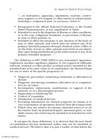
Figure 2.1 shows that design output is really an answer to a request
(design input) plus the evidence to support the decision. From the
list above, we can say that all those design outputs belong in the DHF
at any given time, as depicted in Figure 2.2. However, only items 1
to 6 would end up being part of the DMR. The DHF can be seen as
a “virtual file,” with records showing the relationship between design
input and design output. The key word is “records.” The DMR is
composed of the instructions and criteria needed to make the product.
While the DHF is made of records, the DMR is made of “living
documents.”
Design review
Competent personnel representing functions that are concerned with
the particular design stage under review conduct design reviews at
various (sometimes predetermined) stages of the design and devel-
opment process. There are two key elements in design review. The
first one is the independence between reviewers and design and
development team members. This in fact is the principle behind qual-
ity audits and assessment. Independent eyes and ears are not
“biased.” The second one is the value that a given reviewer brings to
the design and development project (e.g., technical, medical, and
clinical knowledge, among others). Quality system procedures must
ensure that these reviews are formal, planned, documented, and
maintained for future review. If a firm adopts DFSS, the commonly
known tools could facilitate design reviews. For example, a typical
first design review is mostly aimed at assessing the Voice of the
* This is another example of the need for appropriate quality systems. There should be a
procedure to evaluate and qualify suppliers. It shall also describe what documentation is
required to notify the supplier when qualification has been attained.
PH2105_book.fm Page 24 Wednesday, September 22, 2004 1:51 PM
© 2005 by CRC Press
Chapter two: Design Control roadmap 25
Customer (VOC). This is the main design input to any given project.
Records must be kept as part of the DHF. The requirements cascade
or traceability matrix can be used to keep track of reviewed design
items.
Figure 2.1
Relationship among design input, design output, DHF, and DMR.
Figure 2.2
Some DHF elements will become DMR elements.
Design inputs
A
B
C
Correspondence
Design Output
Design and
development
activities
A1
B1
B2
C1
specifications &
procedures
A1
A2
A3
A4
B1
B2
B3
C1
DHF
DMR
Item 1-6
DHF DMR
Device procedures and records
PH2105_book.fm Page 25 Wednesday, September 22, 2004 1:51 PM
© 2005 by CRC Press
26 Six Sigma for Medical Device Design
Formal documented reviews of the design results are planned and
conducted at appropriate stages of the design and development work.
Such stages are to be defined by the design and development plan or
the design change plan.* Reviewers shall have no direct responsibility
(independence). Key ingredients of such reviews are:
1. Documentation (formal)
2. Comprehension (technical, not political)
3. Systematic examination (planned, logical steps)
4. Evaluation of capability of the design and identification of
problems (not to sympathize with the development team)
Design review: practical needs and value added
The value added comes from having an independent body of peers
(“different set of eyes”) reviewing the design. This is especially valu-
able when the review team is strong in customer knowledge, clinical
applications, materials science, reliability, safety, and standards and
regulations. It shall be noted that the design and development of
products and processes is an iterative work. Therefore, identifying
problems, issues, and opportunities is expected in the review process.
During design reviews, an assessment of progress (or lack of it) can
be done. Finally, it is the “OK” for next steps.
Design verification
The company shall ensure that competent personnel verify that the
design outputs satisfy the design input requirements. These activities
must be planned and routinely examined, and the results should be
documented.
What is design verification?
Design verification is a confirmation that the design input require-
ments have been fulfilled by the design output. In some companies,
common sense drove them to adopt similar concepts such as “Design
Engineering Pilot,” “Design Pilot,” and “Engineering Built.” The reg-
ulation aims at providing a sense for formality (i.e., procedures) and
* Thus, design reviews apply to product already in the market that is being exposed to a design
change.
PH2105_book.fm Page 26 Wednesday, September 22, 2004 1:51 PM
© 2005 by CRC Press
Chapter two: Design Control roadmap 27
structure (i.e., design plan*) within the DHF. As indicated in Table
2.5, the firm should prepare itself for successful design verification
by defining quantifiable design inputs and their corresponding
design outputs. In our first book we devoted a section showing how
a design history matrix can help manufacturers to plan and execute
an acceptable design verification. In the DFSS world, such a table is
called a requirements cascade or a requirements traceability matrix.
This tool not only will help the firm to comply with the regulation,
but it is also a good design engineering practice.
Design validation
To ensure that the product conforms to customer requirements and
defined user needs, it is essential that design validation be under-
taken. This will normally be performed on the finished product under
defined conditions. If the product has more than one use, multiple
design validations may be necessary.
Design validation always follows successful design verification.
Design verification is done while the design work is being performed.
The medical device may not be complete or may not be in its final
configuration. To validate design, the team needs to have the final
medical device.
Table 2.5
Example of design input, output, and verification
Design output
Design input
Design
specification DMR
Design
verification
The medical
device will be
used in trauma
rooms. It must
be capable of
withstanding
adverse
conditions (e.g.,
accidental
pulling by the
tubing).
The bond strength
between a luer
lock and tubing
(IV line) shall
withstand P
pounds of axial
force without
detaching from
the tubing.
The raw material
for the luer lock
will be X and the
solvent Y. Before
inserting the
tubing into the
luer lock, the
solvent will be
applied and a
curing of T
minutes will be
allowed.
At 99% reliability
and 95%
confidence, a
Safety Factor of 3
was obtained
during a
stress-strength
test.
* Beyond the generality of the design plan, there shall be performance, quality, and reliability
goals already established. Some firms may decide to include all the project requirements in the
design and development plan; others may decide to establish interdependent quality and
reliability plans in addition to the design and development plan. The same would apply to the
design change plan.
PH2105_book.fm Page 27 Wednesday, September 22, 2004 1:51 PM
© 2005 by CRC Press
28 Six Sigma for Medical Device Design
Design validation includes software and the hardware–software
interface by challenging the source code in its actual use conditions.
For example, embedded software verification is done by emulation
of the source code, while software validation is done once the soft-
ware has been “burned” into the chip or EPROM and the system is
challenged.
Why design validation?
If verification demonstrated that design outputs met design inputs,
why are we validating design? This question can be answered simply
by saying that the design inputs may not be the real thing. That is,
they do not lead the design to meet the customer needs. Also, even
if design inputs are right, then the design outputs could be wrong.
One possible reason could be changes in customer requirements since
the design was initiated. If design inputs and outputs are right, then
there could had been a problem when the design was transferred to
manufacturing.*
Notice that design validation is a final challenge to all the existing
quality systems including Design Control, training of manufacturing
personnel, process validation, and so on. In fact, design validation is
the link to process validation. Also notice that if on one hand, the
output from the process does not meet customer needs and intended
use, the manufacturing process becomes worthless. On the other
hand, if the process is not repeatable or reproducible, then the design
validation is also worthless, since there is no manufacturing process
that can ensure equivalent performance from unit to unit or from
batch to batch.
Design transfer
Design transfer according to the regulation
“Each manufacturer shall establish and maintain procedures to
ensure that the device design is correctly translated into production
specifications” (21 CFR Part 820.30.h). The key words here are “cor-
rectly translated.” This means that an auditor with technical knowl-
edge of the product and process could find a connection between
design outputs and what is stated in the DMR. For example, while
working with external manufacturers, one of the authors realized that
the ranges used in worst-case analysis were different from those
* This is the main reason why initial production units are the best choice for design validation.
PH2105_book.fm Page 28 Wednesday, September 22, 2004 1:51 PM
© 2005 by CRC Press
Chapter two: Design Control roadmap 29
stated in the drafted DMR. The reason was an opportunity for a cost
reduction. The new ranges would imply an extrapolation; that is,
beyond the worst-case analysis range examined for the Operational
Qualification (OQ). Therefore, the change order to release the DMR
had to be rejected and the right ranges were put back.
Practical definition of design transfer
What is really being transferred is knowledge from the design and
development team to the manufacturing or process validation team.
It is of utmost importance that the process validation team (e.g., those
responsible for the “mass production”) understands the device and
its intended use as the first step. DFSS will help to transfer knowledge
via the requirements cascade. It is also relevant the amount and kind
of knowledge that the design and development team have about the
manufacturing process. Careful attention shall be paid to what is done
by R&D and what is to be done by manufacturing development or
process validation personnel.
For example, we can think of process development in two stages.
First, let us consider the design of a new manufacturing machine or
piece of equipment. The design of the new machine is typically done
by a design and development team, sometimes in combination with a
consultant or with the machine manufacturer. But designing a manu-
facturing machine is not synonymous with process characterization.
That is, there is usually a lot of unknown behavior from the newly
designed machine. It is through Design of Experiments (DOE)
and
other DFSS tools used during process characterization that technical
manufacturing personnel could really learn what the input parameters
are that affect the output characteristics and in which way. In other
words, if the manufacturing personnel know what the input parame-
ters are (e.g., independent variables) and how they affect the output
characteristics (e.g., dependent variables), then they may have a way
to control the manufacturing process.
Summarizing this section, when new manufacturing equipment
is designed, there are two main development steps involved; first, the
design per se of the equipment. Second, characterizing the equipment
or machine. Typically, the second step is a function of the “pilot plant.”
If a company is operating in a “direct to site” mode, then the second
development step will have to take place at the manufacturer’s site.
This second development step falls under the definition of OQ, spe-
cifically under the concept of process characterization.
Design transfer may occur via documentation, training, R&D per-
sonnel sent to manufacturing, or manufacturing personnel having
PH2105_book.fm Page 29 Wednesday, September 22, 2004 1:51 PM
© 2005 by CRC Press
30 Six Sigma for Medical Device Design
been part of the design and development team. All the design transfer
activities shall be listed in the design and development plan. How-
ever, training and documentation do not fulfill the whole purpose of
design transfer. The expected results of effective design transfer are:
•Product manufacturability and testability.
•Process repeatability (item to item, within a batch or lot).
•Process reproducibility (lot to lot).
• The process is under statistical control (stable), and thus it is
predictable.
• Manufacturing personnel know what they are doing and what
process parameters need to be adjusted, how to adjust them,
why, and when (here, DFSS will help).
• Adequacy of DMR documents.
• The manufacturing and acceptance specifications are realistic
and meaningful.
• Raw materials and components perform as expected.
• Suppliers know what they are doing.
• There are no surprises.
•A manufacturing process that consistently ensures a medical
device that is safe and effective.
Design changes
All design changes must be authorized by people responsible to
ensure the quality of the product. Procedures shall be established for
identification, documentation, and review of all design changes.
These must follow the same rigorous procedure adopted for the orig-
inal design.
There are four elements involved in controlling design changes.
The matrix in Table 2.6 depicts them.
Document control is a straightforward, classical GMP quality sys-
tem for existing products. It is aimed at enumeration, identification,
status and revision history of manufacturing specifications, testing
instructions, and BOM (i.e., all elements of the DMR). However, once
the design controls are part of the quality systems, the firm needs to
control the documentation that is being “drafted” during design and
development. Many temporary documents exist during the stages of
product design; most of them will be subject to multiple changes.
Thus, the big question is: How can the design and development team
ensure harmonization between the already-approved design
PH2105_book.fm Page 30 Wednesday, September 22, 2004 1:51 PM
© 2005 by CRC Press