Signal processing Part 10 pot
Bạn đang xem bản rút gọn của tài liệu. Xem và tải ngay bản đầy đủ của tài liệu tại đây (790.28 KB, 30 trang )
SignalProcessing264
Ohsumi & Yamaguchi (2006) to estimate the time-delay of signals in nonstationary random
noise, incorporated with the Wigner distribution-based maximum likelihood estimation.
In this paper the signal detection problem is investigated using the stationarization approach
to nonstationary data. The model of the corrupting noise is given by an ARMA(p, q) model
with unknown time-varying coefficients. These coefficient parameters are estimated from the
(original) observation data by the Kalman filter.
2. Problem Statement
Let {y(k)} be the (scalar) observation data taken at sampling time instant t
k
(k = 1, 2, ···),
and assume that it can be expressed as
y
(k) = s(k) + n(k) (k = 1, 2, ···), (1)
where s
(·) is a signal to be detected, whose form is surely known, and is assumed to exist
in a brief interval if it exists; and n
(·) is the nonstationary random noise. In consequence,
the observation data
{y(k)} becomes nonstationary, but its trend time series is assumed to be
removed by the process
y
(k) = ∆
d
Y(k), (2)
where Y
(k) is the original data received by the receiver; ∆Y(k) = Y(k) − Y(k −1); and d
indicates the order.
In this paper the random noise n
(k) is assumed to be given as the output of ARMA(p, q)
model with time-varying coefficient parameters:
n
(k) +
p
∑
i=1
α
i
(k)n(k −i) =
q
∑
j=1
β
j
(k)w(k − j) + w(k), (3)
where w
(·) is the white Gaussian noise with zero-mean and variance parameter σ
2
; {α
i
(·)}
and {β
j
(·)} are slowly and smoothly varying parameters to be specified.
Then our purpose is to propose a method of detecting the signal s
(k) from the noisy observa-
tion data
{y(k)}.
The procedure taken in this paper is as follows:
(i) First, based on the noise model (3), coefficient functions
{α
i
(·)} and {β
j
(·)} are estimated
using Kalman filter from the observation data
{y(k)}.
(ii) Using the estimates
{
ˆ
α
i
(·)} and {
ˆ
β
j
(·)} obtained in (i), the observation data y(k) is modi-
fied to become stationary. This procedure is called the stationarization of observation data.
(iii) Using the stationarized observation data
ˆ
y
(k), the signal detection is based on the model
ˆ
y
(k) =
ˆ
s
(k) + w(k), (4)
where
ˆ
s
(k) is the modified signal. Equation (4) is familiar in the conventional signal detection
problem where the noise is stationary.
3. Stationarization of Observation Data
Recalling the assumption that the duration of the signal s(k) is short, neglect the signal in the
observation data and consider the signal-free case, i.e., y
(k) = n(k), then the observation data
y
(k) is expressed by (1) and (3) as follows:
y
(k) = −
p
∑
i=1
α
i
(k)y(k −i) +
q
∑
j=1
β
j
(k)w(k − j) + w(k). (5)
In order to estimate the time-varying parameters
{α
i
(k)} and {β
j
(k)} in (5), suppose that they
change from step k
−1 to k under random effects {e
·
(k)}. Define vectors
x
(k) =
−α
1
(k)
.
.
.
−α
p
(k)
β
1
(k)
.
.
.
β
q
(k)
, v
(k) =
−e
1
(k)
.
.
.
−e
p
(k)
e
p+1
(k)
.
.
.
e
p+q
(k)
. (6)
Then,
{α
i
(k)} and {β
j
(k)} are subject to the dynamics,
x
(k + 1) = x(k) + v(k), (7)
where
{e
·
(k)} are assumed to be Gaussian with zero-means and variances τ
2
1
, ··· , τ
2
p
+q
.
Then, Eq. (5) is expressed formally as
y
(k) = H(k)x(k) + w(k) (8)
in which H
(k) is given by
H
(k) = [ y(k −1), ··· , y(k − p), w(k −1), ··· , w(k − q)] . (9)
At this stage it should be noted that the matrix H
(k) consists of the (unmeasurable) past noise
sequence
{w(·)}. To remedy this inadequate situation, we resort to replace it by
ˆ
H
(k) = [ y(k −1), ··· , y(k − p), ν
m
(k −1 ), ··· , ν
m
(k −q)] (10)
in which
{ν
m
(·)} is the sequence modified from the innovation sequence ν(·) as
ν
m
() = c() ν() ( = k −q, k −q + 1, ···, k −1) , (11)
where
ν
() = y() −
ˆ
H
()
ˆ
x
(| −1) (12)
and
c
() =
1
+
1
σ
2
ˆ
H
()P(| −1)
ˆ
H
T
()
−
1
2
. (13)
Here,
ˆ
x
(| −1) and P( | −1) are the one-step prediction and its covariance matrix computed
by Kalman filter for the past interval.
DetectionofSignalsinNonstationaryNoiseviaKalmanFilter-BasedStationarizationApproach 265
Ohsumi & Yamaguchi (2006) to estimate the time-delay of signals in nonstationary random
noise, incorporated with the Wigner distribution-based maximum likelihood estimation.
In this paper the signal detection problem is investigated using the stationarization approach
to nonstationary data. The model of the corrupting noise is given by an ARMA(p, q) model
with unknown time-varying coefficients. These coefficient parameters are estimated from the
(original) observation data by the Kalman filter.
2. Problem Statement
Let {y(k)} be the (scalar) observation data taken at sampling time instant t
k
(k = 1, 2, ···),
and assume that it can be expressed as
y
(k) = s(k) + n(k) (k = 1, 2, ···), (1)
where s
(·) is a signal to be detected, whose form is surely known, and is assumed to exist
in a brief interval if it exists; and n
(·) is the nonstationary random noise. In consequence,
the observation data
{y(k)} becomes nonstationary, but its trend time series is assumed to be
removed by the process
y
(k) = ∆
d
Y(k), (2)
where Y
(k) is the original data received by the receiver; ∆Y(k) = Y(k) − Y(k −1); and d
indicates the order.
In this paper the random noise n
(k) is assumed to be given as the output of ARMA(p, q)
model with time-varying coefficient parameters:
n
(k) +
p
∑
i=1
α
i
(k)n(k −i) =
q
∑
j=1
β
j
(k)w(k − j) + w(k), (3)
where w
(·) is the white Gaussian noise with zero-mean and variance parameter σ
2
; {α
i
(·)}
and {β
j
(·)} are slowly and smoothly varying parameters to be specified.
Then our purpose is to propose a method of detecting the signal s
(k) from the noisy observa-
tion data
{y(k)}.
The procedure taken in this paper is as follows:
(i) First, based on the noise model (3), coefficient functions
{α
i
(·)} and {β
j
(·)} are estimated
using Kalman filter from the observation data
{y(k)}.
(ii) Using the estimates
{
ˆ
α
i
(·)} and {
ˆ
β
j
(·)} obtained in (i), the observation data y(k) is modi-
fied to become stationary. This procedure is called the stationarization of observation data.
(iii) Using the stationarized observation data
ˆ
y
(k), the signal detection is based on the model
ˆ
y
(k) =
ˆ
s
(k) + w(k), (4)
where
ˆ
s
(k) is the modified signal. Equation (4) is familiar in the conventional signal detection
problem where the noise is stationary.
3. Stationarization of Observation Data
Recalling the assumption that the duration of the signal s(k) is short, neglect the signal in the
observation data and consider the signal-free case, i.e., y
(k) = n(k), then the observation data
y
(k) is expressed by (1) and (3) as follows:
y
(k) = −
p
∑
i=1
α
i
(k)y(k −i) +
q
∑
j=1
β
j
(k)w(k − j) + w(k). (5)
In order to estimate the time-varying parameters
{α
i
(k)} and {β
j
(k)} in (5), suppose that they
change from step k
−1 to k under random effects {e
·
(k)}. Define vectors
x
(k) =
−α
1
(k)
.
.
.
−α
p
(k)
β
1
(k)
.
.
.
β
q
(k)
, v
(k) =
−e
1
(k)
.
.
.
−e
p
(k)
e
p+1
(k)
.
.
.
e
p+q
(k)
. (6)
Then,
{α
i
(k)} and {β
j
(k)} are subject to the dynamics,
x
(k + 1) = x(k) + v(k), (7)
where
{e
·
(k)} are assumed to be Gaussian with zero-means and variances τ
2
1
, ··· , τ
2
p
+q
.
Then, Eq. (5) is expressed formally as
y
(k) = H(k)x(k) + w(k) (8)
in which H
(k) is given by
H
(k) = [ y(k −1), ··· , y(k − p), w(k −1), ··· , w(k − q)] . (9)
At this stage it should be noted that the matrix H
(k) consists of the (unmeasurable) past noise
sequence
{w(·)}. To remedy this inadequate situation, we resort to replace it by
ˆ
H
(k) = [ y(k −1), ··· , y(k − p), ν
m
(k −1 ), ··· , ν
m
(k −q)] (10)
in which
{ν
m
(·)} is the sequence modified from the innovation sequence ν(·) as
ν
m
() = c() ν() ( = k −q, k −q + 1, ···, k −1) , (11)
where
ν
() = y() −
ˆ
H
()
ˆ
x
(| −1) (12)
and
c
() =
1
+
1
σ
2
ˆ
H
()P(| −1)
ˆ
H
T
()
−
1
2
. (13)
Here,
ˆ
x
(| −1) and P( | −1) are the one-step prediction and its covariance matrix computed
by Kalman filter for the past interval.
SignalProcessing266
It is a simple exercise to show that the statistical properties of ν
m
(·) is the same as that of w(· ),
i.e., E
{ν
m
(k)} = 0 and E{|ν
m
(k)|
2
} = σ
2
(for proof, see Appendix). Then, instead of (8) we
have the expression,
y
(k) =
ˆ
H
(k)x(k) + w(k) . (14)
The procedure for computing
ˆ
H
(k) is stated as follows:
(i) Preliminaries: Assume for the past k
(< 0) that {ν
m
(−1), ν
m
(−2), ···, ν
m
(−q)}are set appro-
priately (may be set all zero), and preassign
ˆ
x
(0| −1),
ˆ
P(0|− 1) and
ˆ
H(0) as initial values.
Then, at time k
(k = 0, 1, 2, ···)
(ii) Computation of ν() and c(): Compute the innovation ν() and coefficient c() by (12) and
(13) using
ˆ
H
() = [ y( −1), ···, y( − p), ν
m
( −1), ···, ν
m
( −q)].
(iii) Computation of ν
m
(): Compute ν
m
() by (11) using ν() and c() obtained in the previous
step.
Repeat Steps (ii) and (iii) for
= k − q, k − q + 1, ···, k −1 to obtain
ˆ
H(k). In computing (12)
and (13),
ˆ
x
(| −1) and P(| −1) are computed by the Kalman filter (e.g., Jazwinski, 1970):
ˆ
x
( + 1|) =
ˆ
x
(|) (15)
ˆ
x
(|) =
ˆ
x
(| −1) + K()ν(), (16)
K
() =
1
ˆ
H
()P(| −1)
ˆ
H
T
() + σ
2
P(| −1)
ˆ
H
T
() (17)
P
( + 1|) = P(|) + Q (18)
P
(|) = P(| −1) −K()
ˆ
H
()P(| −1), (19)
where Q
= diag {τ
2
1
, ··· , τ
2
p
+q
}.
Thus, the estimates of the coefficient parameters
{α
i
(k)} and {β
j
(k)} are obtained by the
Kalman filter constructed for (7) and (14) (whose form is the same as (15)-(19) replacing
by the present k). Under the basic assumption that the coefficient parameters vary slowly and
smoothly, they can be treated like constants in an interval I
k
around the current time k. Write
them as
ˆ
α
ik
and
ˆ
β
jk
in I
k
. Replacing the past {w(k − j)} in (5) by the statistically equivalent
sequence
{ν
m
(k − j )}, define the sequence
ˆ
y(k) by
ˆ
y
(k) := y(k) +
p
∑
i=1
ˆ
α
ik
y(k − i) −
q
∑
j=1
ˆ
β
jk
ν
m
(k − j). (20)
Then, we have the following adequate approximation for (5),
ˆ
y
(k) = w(k) (21)
which implies that the sequence
{
ˆ
y
(k)} is stationary because w(k) is the stationary white
noise.
4. Signal Detection
After obtained the estimates of coefficient parameters, the observation process (14) may be
written using estimates as
y
(k) =
ˆ
H
(k)
ˆ
x
(k|k) + w(k) (22)
or
y
(k) +
p
∑
i=1
ˆ
α
ik
y(k − i) =
q
∑
j=1
ˆ
β
jk
ν
m
(k − j) + w(k). (23)
Now, let us revive the signal s
(k) in the observation data. To do this, replace {y(k)} formally
by
{y(k) − s(k)} in (23) to obtain
y
(k) +
p
∑
i=1
ˆ
α
ik
y(k − i) =
s
(k) +
p
∑
i=1
ˆ
α
ik
s(k − i)
+
q
∑
j=1
ˆ
β
jk
ν
m
(k − j) + w(k) (24)
or
ˆ
y
(k) =
ˆ
s
(k) + w(k), (4)
bis
where
ˆ
y(k) has the same form as (20) and
ˆ
s
(k) = s(k) +
p
∑
i=1
ˆ
α
ik
s(k − i). (25)
Note that (4)
bis
is familiar to us as the mathematical model for the detection problem of signals
in stationary noise (e.g., Van Trees, 1968).
Now, consider the binary hypotheses: H
1
:
ˆ
y(k) =
ˆ
s
(k) + w(k), and H
0
:
ˆ
y(k) = w(k), and let
ˆ
Y
k
be the stationarized observation data taken up to k,
ˆ
Y
k
= {
ˆ
y
(), = 1, 2, ··· , k }. Since the ad-
ditive noise w
(k) is white Gaussian sequence with zero-mean and variance σ
2
, the likelihood-
ratio function Λ
(k) = p{
ˆ
Y
k
|H
1
}/
ˆ
Y
k
|H
0
} is evaluated as follows:
Λ
(k) =
k
∏
=1
(2π)
−
1
2
exp
−
{
ˆ
y
() −
ˆ
s
()}
2
2σ
2
k
∏
=1
(2π)
−
1
2
exp
−
ˆ
y
2
()
2σ
2
. (26)
We use rather its logarithmic form,
L
(k) := ln Λ(k)
=
1
σ
2
k
∑
=1
ˆ
s
()
ˆ
y
() −
1
2σ
2
k
∑
=1
ˆ
s
2
() (27)
as the signal detector.
5. Simulation Studies
In this section, we provide a typical set of several simulation results to demonstrate the pro-
posed method.
(i) Experiment 1.
DetectionofSignalsinNonstationaryNoiseviaKalmanFilter-BasedStationarizationApproach 267
It is a simple exercise to show that the statistical properties of ν
m
(·) is the same as that of w(· ),
i.e., E
{ν
m
(k)} = 0 and E{|ν
m
(k)|
2
} = σ
2
(for proof, see Appendix). Then, instead of (8) we
have the expression,
y
(k) =
ˆ
H
(k)x(k) + w(k) . (14)
The procedure for computing
ˆ
H
(k) is stated as follows:
(i) Preliminaries: Assume for the past k
(< 0) that {ν
m
(−1), ν
m
(−2), ···, ν
m
(−q)}are set appro-
priately (may be set all zero), and preassign
ˆ
x
(0| −1),
ˆ
P(0|− 1) and
ˆ
H(0) as initial values.
Then, at time k
(k = 0, 1, 2, ···)
(ii) Computation of ν() and c(): Compute the innovation ν() and coefficient c() by (12) and
(13) using
ˆ
H
() = [ y( −1), ···, y( − p), ν
m
( −1), ···, ν
m
( −q)].
(iii) Computation of ν
m
(): Compute ν
m
() by (11) using ν() and c() obtained in the previous
step.
Repeat Steps (ii) and (iii) for
= k − q, k − q + 1, ···, k −1 to obtain
ˆ
H(k). In computing (12)
and (13),
ˆ
x
(| −1) and P(| −1) are computed by the Kalman filter (e.g., Jazwinski, 1970):
ˆ
x
( + 1|) =
ˆ
x
(|) (15)
ˆ
x
(|) =
ˆ
x
(| −1) + K()ν(), (16)
K
() =
1
ˆ
H
()P(| −1)
ˆ
H
T
() + σ
2
P(| −1)
ˆ
H
T
() (17)
P
( + 1|) = P(|) + Q (18)
P
(|) = P(| −1) −K()
ˆ
H
()P(| −1), (19)
where Q
= diag {τ
2
1
, ··· , τ
2
p
+q
}.
Thus, the estimates of the coefficient parameters
{α
i
(k)} and {β
j
(k)} are obtained by the
Kalman filter constructed for (7) and (14) (whose form is the same as (15)-(19) replacing
by the present k). Under the basic assumption that the coefficient parameters vary slowly and
smoothly, they can be treated like constants in an interval I
k
around the current time k. Write
them as
ˆ
α
ik
and
ˆ
β
jk
in I
k
. Replacing the past {w(k − j)} in (5) by the statistically equivalent
sequence
{ν
m
(k − j )}, define the sequence
ˆ
y(k) by
ˆ
y
(k) := y(k) +
p
∑
i=1
ˆ
α
ik
y(k − i) −
q
∑
j=1
ˆ
β
jk
ν
m
(k − j). (20)
Then, we have the following adequate approximation for (5),
ˆ
y
(k) = w(k) (21)
which implies that the sequence
{
ˆ
y
(k)} is stationary because w(k) is the stationary white
noise.
4. Signal Detection
After obtained the estimates of coefficient parameters, the observation process (14) may be
written using estimates as
y
(k) =
ˆ
H
(k)
ˆ
x
(k|k) + w(k) (22)
or
y
(k) +
p
∑
i=1
ˆ
α
ik
y(k − i) =
q
∑
j=1
ˆ
β
jk
ν
m
(k − j) + w(k). (23)
Now, let us revive the signal s
(k) in the observation data. To do this, replace {y(k)} formally
by
{y(k) − s(k)} in (23) to obtain
y
(k) +
p
∑
i=1
ˆ
α
ik
y(k − i) =
s
(k) +
p
∑
i=1
ˆ
α
ik
s(k − i)
+
q
∑
j=1
ˆ
β
jk
ν
m
(k − j) + w(k) (24)
or
ˆ
y
(k) =
ˆ
s
(k) + w(k), (4)
bis
where
ˆ
y(k) has the same form as (20) and
ˆ
s
(k) = s(k) +
p
∑
i=1
ˆ
α
ik
s(k − i). (25)
Note that (4)
bis
is familiar to us as the mathematical model for the detection problem of signals
in stationary noise (e.g., Van Trees, 1968).
Now, consider the binary hypotheses: H
1
:
ˆ
y(k) =
ˆ
s
(k) + w(k), and H
0
:
ˆ
y(k) = w(k), and let
ˆ
Y
k
be the stationarized observation data taken up to k,
ˆ
Y
k
= {
ˆ
y
(), = 1, 2, ··· , k }. Since the ad-
ditive noise w
(k) is white Gaussian sequence with zero-mean and variance σ
2
, the likelihood-
ratio function Λ
(k) = p{
ˆ
Y
k
|H
1
}/
ˆ
Y
k
|H
0
} is evaluated as follows:
Λ
(k) =
k
∏
=1
(2π)
−
1
2
exp
−
{
ˆ
y
() −
ˆ
s
()}
2
2σ
2
k
∏
=1
(2π)
−
1
2
exp
−
ˆ
y
2
()
2σ
2
. (26)
We use rather its logarithmic form,
L
(k) := ln Λ(k)
=
1
σ
2
k
∑
=1
ˆ
s
()
ˆ
y
() −
1
2σ
2
k
∑
=1
ˆ
s
2
() (27)
as the signal detector.
5. Simulation Studies
In this section, we provide a typical set of several simulation results to demonstrate the pro-
posed method.
(i) Experiment 1.
SignalProcessing268
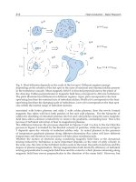
The top of Fig.1 depicts a sample path of the observation data {Y(k)}generated by calculating
the output of the ARMA(4, 1)-model:
n
(k) = −
4
∑
i=1
α
i
(k)n(k −i) + β (k)w(k −1) + w(k) .
Time-varying coefficients
{α
i
(k)} and β(k) are set as
α
1
(k) = −1.24 sin(0.002k − 0.95), α
2
(k) = 0.38 − 2 cos(0.004k − 1.89)
α
3
(k) = α
1
(k), α
4
(k) = 1, β(k) = 1.5.
The bottom of Fig.1 shows a signal embedded in the observation data around k
= 300 given
by
s
() = 12 e
−2.78
2
sin(1.26),
where
= k −300. Figure 2 depicts trend-removed data and stationarized data
ˆ
y(k). The
trend was removed by setting d
= 1. For the Kalman filter (15)∼(19), the parameters are set
0 100 200 300 400 500 600 700 800 900 1000
-150
-100
-50
0
50
100
150
kstep
OBSAERVATIONDATAY(k)
0 100 200 300 400 500 600 700 800 900 1000
-150
-100
-50
0
50
100
150
kstep
EMBEDDEDSIGNALs(k)
Fig. 1. A sample path of the observation data Y(k) (top) and the embedded signal s(k) (bot-
tom).
0 100 200 300 400 500 600 700 800 900 1000
-60
-40
-20
0
20
40
60
kstep
TREND-REMOVEDDATAy(k)
0 100 200 300 400 500 600 700 800 900 1000
-20
-10
0
10
20
kstep
STATIONARIZEDOBSERVATIONDATA
Fig. 2. The trend-removed data y(k) (top) and the stationarized observation data
ˆ
y(k) (bot-
tom).
DetectionofSignalsinNonstationaryNoiseviaKalmanFilter-BasedStationarizationApproach 269
The top of Fig.1 depicts a sample path of the observation data {Y(k)}generated by calculating
the output of the ARMA(4, 1)-model:
n
(k) = −
4
∑
i=1
α
i
(k)n(k −i) + β (k)w(k −1) + w(k) .
Time-varying coefficients
{α
i
(k)} and β(k) are set as
α
1
(k) = −1.24 sin(0.002k − 0.95), α
2
(k) = 0.38 − 2 cos(0.004k − 1.89)
α
3
(k) = α
1
(k), α
4
(k) = 1, β(k) = 1.5.
The bottom of Fig.1 shows a signal embedded in the observation data around k
= 300 given
by
s
() = 12 e
−2.78
2
sin(1.26),
where
= k −300. Figure 2 depicts trend-removed data and stationarized data
ˆ
y(k). The
trend was removed by setting d
= 1. For the Kalman filter (15)∼(19), the parameters are set
0 100 200 300 400 500 600 700 800 900 1000
-150
-100
-50
0
50
100
150
kstep
OBSAERVATIONDATAY(k)
0 100 200 300 400 500 600 700 800 900 1000
-150
-100
-50
0
50
100
150
kstep
EMBEDDEDSIGNALs(k)
Fig. 1. A sample path of the observation data Y(k) (top) and the embedded signal s(k) (bot-
tom).
0 100 200 300 400 500 600 700 800 900 1000
-60
-40
-20
0
20
40
60
kstep
TREND-REMOVEDDATAy(k)
0 100 200 300 400 500 600 700 800 900 1000
-20
-10
0
10
20
kstep
STATIONARIZEDOBSERVATIONDATA
Fig. 2. The trend-removed data y(k) (top) and the stationarized observation data
ˆ
y(k) (bot-
tom).
SignalProcessing270
0 100 200 300 400 500 600 700 800 900 1000
-1000
-500
0
500
1000
1500
kstep
Log-likelihoodratioL(k)
Fig. 3. Log-likelihood function L(k).
as Q
= diag {0.05, 0.05, 0.05, 0.05, 0.05} and σ
2
= 40. It should be noted that from Fig. 2 the
observation data is well stationarized and that even in this figure the signal emerges from the
background noise.
Figure 3 shows the result of signal detection by the current log-likelihood ratio function L
(k).
Clearly, it exhibits a salient peak around the true time instant k
= 300 and this shows the
existence of the signal.
(ii) Experiment 2.
Efficacy of the signal detector proposed in this paper is also tested for the pulse signal.
Figure 4 depicts observation data and embedded three pulses. Random noise n
(k) is gener-
ated by the same manner of previous simulation with same coefficients α
i
(k) and β(k). As a
signals s
(k), a train of pulses with same magnitude is considered:
s
(k) =
20 for D
i
≤ k < D
i
+ 5 (i = 1, 2, 3)
0 otherwise,
where D
1
= 200, D
2
= 500, D
3
= 800.
Figure 5 depicts trend-removed data and stationarized data
ˆ
y(k). The trend was also removed
by setting d
= 1. The parameters of Kalman filter are set as the same of previous experiment.
Figure 6 shows the result of signal detection. Clearly, log-likelihood ratio function L
(k)
has large value around each time when each pulse exists. Thus the signal detection is well
succeeded.
0 100 200 300 400 500 600 700 800 900 1000
-200
-100
0
100
200
kstep
OBSAERVATIONDATAY(k)
0 100 200 300 400 500 600 700 800 900 1000
-200
-100
0
100
200
kstep
EMBEDDEDSIGNALs(k)
Fig. 4. A sample path of the observation data Y(k) (top) and the pulse signal s(k) (bottom).
DetectionofSignalsinNonstationaryNoiseviaKalmanFilter-BasedStationarizationApproach 271
0 100 200 300 400 500 600 700 800 900 1000
-1000
-500
0
500
1000
1500
kstep
Log-likelihoodratioL(k)
Fig. 3. Log-likelihood function L(k).
as Q
= diag {0.05, 0.05, 0.05, 0.05, 0.05} and σ
2
= 40. It should be noted that from Fig. 2 the
observation data is well stationarized and that even in this figure the signal emerges from the
background noise.
Figure 3 shows the result of signal detection by the current log-likelihood ratio function L
(k).
Clearly, it exhibits a salient peak around the true time instant k
= 300 and this shows the
existence of the signal.
(ii) Experiment 2.
Efficacy of the signal detector proposed in this paper is also tested for the pulse signal.
Figure 4 depicts observation data and embedded three pulses. Random noise n
(k) is gener-
ated by the same manner of previous simulation with same coefficients α
i
(k) and β(k). As a
signals s
(k), a train of pulses with same magnitude is considered:
s
(k) =
20 for D
i
≤ k < D
i
+ 5 (i = 1, 2, 3)
0 otherwise,
where D
1
= 200, D
2
= 500, D
3
= 800.
Figure 5 depicts trend-removed data and stationarized data
ˆ
y(k). The trend was also removed
by setting d
= 1. The parameters of Kalman filter are set as the same of previous experiment.
Figure 6 shows the result of signal detection. Clearly, log-likelihood ratio function L
(k)
has large value around each time when each pulse exists. Thus the signal detection is well
succeeded.
0 100 200 300 400 500 600 700 800 900 1000
-200
-100
0
100
200
kstep
OBSAERVATIONDATAY(k)
0 100 200 300 400 500 600 700 800 900 1000
-200
-100
0
100
200
kstep
EMBEDDEDSIGNALs(k)
Fig. 4. A sample path of the observation data Y(k) (top) and the pulse signal s(k) (bottom).
SignalProcessing272
0 100 200 300 400 500 600 700 800 900 1000
-60
-40
-20
0
20
40
60
80
kstep
TREND-REMOVEDDATAy(k)
0 100 200 300 400 500 600 700 800 900 1000
-20
-10
0
10
20
30
kstep
STATIONARIZEDOBSERVATIONDATA
Fig. 5. The trend-removed data (top) and the stationarized observation data
ˆ
y(k) (bottom).
0 100 200 300 400 500 600 700 800 900 1000
-1500
-1000
-500
0
500
1000
1500
2000
2500
3000
kstep
Log-likelihoodratioL(k)
Fig. 6. Log-likelihood function L(k).
6. Conclusion
The efficacy of the proposed signal detection method based on the stationarization of
nonstationary observation data has been confirmed by simulation studies. The key to use the
Kalman filter to estimate the coefficient parameters of the ARMA noise model is laid on the
replacement of the unobservable past noise sequence by the equivalent (modified) innovation
sequence which is observation data-measurable. The stationarization of a nonstationary data
as introduced in this paper will have potential ability to treat the nonstationary noise or
observation data in the signal processing.
Appendix. Proof of Statistical Equivalence Between {w(k)} and {ν
m
(k)}
The mean of the modified innovation sequence ν
m
(k) is clearly zero. Indeed,
E{ν
m
(k)} = c(k)E{ν(k)}
=
c(k)E{y(k) −
ˆ
H
(k)
ˆ
x
(k|k −1)}.
DetectionofSignalsinNonstationaryNoiseviaKalmanFilter-BasedStationarizationApproach 273
0 100 200 300 400 500 600 700 800 900 1000
-60
-40
-20
0
20
40
60
80
kstep
TREND-REMOVEDDATAy(k)
0 100 200 300 400 500 600 700 800 900 1000
-20
-10
0
10
20
30
kstep
STATIONARIZEDOBSERVATIONDATA
Fig. 5. The trend-removed data (top) and the stationarized observation data
ˆ
y(k) (bottom).
0 100 200 300 400 500 600 700 800 900 1000
-1500
-1000
-500
0
500
1000
1500
2000
2500
3000
kstep
Log-likelihoodratioL(k)
Fig. 6. Log-likelihood function L(k).
6. Conclusion
The efficacy of the proposed signal detection method based on the stationarization of
nonstationary observation data has been confirmed by simulation studies. The key to use the
Kalman filter to estimate the coefficient parameters of the ARMA noise model is laid on the
replacement of the unobservable past noise sequence by the equivalent (modified) innovation
sequence which is observation data-measurable. The stationarization of a nonstationary data
as introduced in this paper will have potential ability to treat the nonstationary noise or
observation data in the signal processing.
Appendix. Proof of Statistical Equivalence Between {w(k)} and {ν
m
(k)}
The mean of the modified innovation sequence ν
m
(k) is clearly zero. Indeed,
E{ν
m
(k)} = c(k)E{ν(k)}
=
c(k)E{y(k) −
ˆ
H
(k)
ˆ
x
(k|k −1)}.
SignalProcessing274
Here, recalling that y(k) is given by the form (14), we have
= c(k)[
ˆ
H
(k)E{x(k) −
ˆ
x
(k|k −1)}+ E{w(k)}]
=
c(k)
ˆ
H
(k)E{E{x(k) −
ˆ
x
(k|k −1)|Y
k−1
}}
=
c(k)
ˆ
H
(k)E{E{x(k)|Y
k−1
}−
ˆ
x
(k|k −1)}
=
0,
where Y
k−1
= {y(), 0 ≤ ≤ k −1}.
Next, the variance of ν
m
(k) is evaluated as follows:
E{ν
2
m
(k)} = c
2
(k)E{ν
2
(k)}
=
c
2
(k)E{[
ˆ
H
(k)[x(k) −
ˆ
x
(k|k −1)] + w(k)]
2
}
=
c
2
(k)[
ˆ
H
(k)E{[x(k) −
ˆ
x
(k|k −1)][x(k) −
ˆ
x
(k|k −1)]
T
}
ˆ
H
T
(k) + E{w
2
(k)}]
=
c
2
(k)[
ˆ
H
(k)P(k|k −1)
ˆ
H
T
(k) + σ
2
].
If we select c
(k) as (13), the variance of ν
m
(k)-sequence becomes σ
2
which is just the variance
of
{w(k)}.
(Q.E.D.)
7. References
Haykin, S. (1996). Neural networks expand SP’s horizons. IEEE Signal Processing Mag., Vol.13,
No.2, pp.24-29
Haykin, S. & Bhattacharya, T. K. (1997). Modular learning strategy for signal detection in a
nonstationary environment. IEEE Trans. Signal Processing, Vol.45, No.6, pp.1619-1637
Haykin, S. & Thomson, D. J. (1998). Signal detection in a nonstationary environment reformu-
lated as an adaptive pattern classification problem. Proc. of the IEEE, Vol.86, No.11,
pp.2325-2344
Ijima, H., Ohsumi, A. & Okui, R. (2006). A method of detection of signals corrupted by non-
stationary random noise via stationarization of the data, Trans. IEICE, Fundamentals
of Electronics, Communications and Computer Sciences, Vol. J89-A, No.6, pp.535-543 (in
Japanese)
Ijima, H., Ohsumi, A. & Yamaguchi, S. (2006). Nonlinear parametric estimation for signals in
nonstationary random noise via stationarization and Wigner distribution, Proc. 2006
Int. Symp. Nonlinear Theory and its Applic. (NOLTA 2006), Bologna, Italy, pp.851-854
Ijima, H., Okui, R. & Ohsumi, A. (2005). Detection of signals is nonstationary random noise via
staionarization and stationary test, Proc. IEEE Workshop on Statistical Signal Processing
(SSP’05), Bordeaux, France, Paper ID 68
Jazwinski A. H. (1970). Stochastic Processes and Filtering Theory, Academic Press, New York
Van Trees, H. L. (1968). Detection, Estimation, and Modulation Theory, Part I, John Wiley
DirectDesignofInniteImpulseResponseFiltersbasedonAllpoleFilters 275
Direct Design of Innite Impulse Response Filters based on Allpole
Filters
AlfonsoFernandez-VazquezandGordanaJovanovicDolecek
0
Direct Design of Infinite Impulse
Response Filters based on Allpole Filters
Alfonso Fernandez-Vazquez and Gordana Jovanovic Dolecek
Department of Electronics
INAOE, Puebla, Mexico
P.O. Box 51 and 216, 72000
Tel/Fax: +52 222 2470517
,
This chapter presents a new framework to design different types of IIR filters based on the
general technique for maximally flat allpole filter design. The resul ting allpole filters have
some desire d characteristics, i.e., desired degre e of flatness and group delay, and the desired
phase response at any prescribed set of frequency points. Those characteristics are important
to define the corresponding IIR filters. The design includes both real and complex cases.
In that way we develop a direct d esign method for linear-phase Butterworth-like filters, using
the same specification as in traditional analog-based IIR filter design. The design includes the
design of lowpass filters as well as highpass filters. The designed filters can be either real or
complex. The design of liner-phase two-band filter banks is also discussed.
Additionally, we discussed the designs of some special filters such as Butterworth-lik e filters
with improved group delay, complex wavelet filters, and fractional Hilbert transformers.
Finally, we addressed a new de sign of IIR filters based on three allpass filters. As a result we
propose a new design of lowpass filters with a desired characteristic based on the complex
allpole filters.
Closed form equations for the computation o f the filter coefficients are provided. All design
techniques are illustrated with examples.
1. Introduction
The des ign of allpole filters has been attractive in the l ast years due to some promising appli-
cations, lik e the design of allpass filters (Chan et al., 2005; Lang, 1998; Pun & Chan, 2003; Se-
lesnick, 1999; Zhang & Iwak ura, 1999), the design of orthogonal and biorthogonal IIR wavelet
filters (Selesnick, 1998; Zhang et al., 2001; 2000; 2006), the design of complex wavelets (Fernan-
des et al., 2003), the design of half band filters (Zhang & Amaratunga, 2002), the filter bank
design (Kim & Yoo, 2003; Lee & Yang, 2004; Saramaki & Bregovic, 2002), the fractional de lay
filter design (Laakso et al., 1996), the fractional Hilbert transform (Pei & Wang, 2002), notch
filters (Joshi & Roy, 1999; Pei & Tseng, 1997; Tseng & Pei, 1998), among others. The majority
of the methods us e some approximation of the desired phase in the least square sense and
minimax sense.
The allpole filters with maximally flat phase response characteristic have been specially attrac-
tive due to promising applicati ons, like the design of IIR filters (Selesnick, 1999), the design
14
SignalProcessing276
of orthogonal and biorthogonal IIR wavelet filters (Selesnick, 1998; Zhang et al., 2001; 2000;
2006), the design of complex wavelets (Fernandes et al., 2003), the design of half band filters
(Zhang & Amaratunga, 2002), the fractional delay filter design (Laakso et al., 1996) and the
fractional Hilbert transform design (Pei & Wang, 2002).
This chapter presents a new design of real and complex allpole filters with the given phase,
group delay, and degree of flatness, at any desired set of frequency points. The main moti-
vation of this work is to get some new p romising cases related with the applications of max-
imally flat allpole filter s. In that way, using the proposed extended al lpole filter design, we
introduced some new special cases.
The rest of the chapter is organized as follows. Section 2 establishes the general equations for
maximally flat real and complex allpole filters. The discussion of the propo sed design is given
in Section 3 for both, real and complex cases. Different special cases of the general allpole
filter de sign is discussed in Section 4. Finally, Section 5 presents some applications o f the
proposed allpole filter design, i.e., l inear-phase Butterworth-like filter, Butterworth-like filters
with improved group delay, complex wavelet filters, fractional Hilbert transformers, and new
IIR filters based on three allpass filters.
2. Equations for Maximally Flat Allpole Filter
We deri ve here equations for real and complex allpole filters both of order N, d elay τ, and
degree of flatness K, at a given set of frequency points.
We consider that an allpole filter of order N is given by,
D
(z) =
α
F(z)
, (1)
where α is a complex constant with unit magnitude, z is the complex variable, and F
(z) is a
polynomial of degree N,
F
(z) = 1 +
N
∑
n=1
f
n
z
−n
. (2)
In g ener al, the filter coefficients f
n
, n = 1, . . . , N, are complex, i .e., f
n
= f
Rn
+ jf
In
where f
Rn
and f
In
are the real and imaginary parts of f
n
, respectively. Obviously, if f
In
= 0, we obtain
real coefficients.
The phase responses of D
(z) and F(z) are related by
φ
D
(ω) = φ
α
−φ
F
(ω), (3)
where φ
α
is the phase of α, and φ
D
(ω) and φ
F
(ω) are the phases of D(z) and F(z), respectively.
The corresponding group delay is the negative derivative of the phase, as shown in (4).
G
(ω) = −
dφ
D
(ω)
dω
=
dφ
F
(ω)
dω
. (4)
The conditions for the maximally flat group delay at the desire d frequency point ω are
G
(ω) = τ (5a)
G
(p)
(ω) = 0, p = 1, . . . , K, (5b)
where τ is the desired group delay, K is the de gree of flatness, and G
(p)
(ω) indicates the pth
derivative of G
(ω).
By performing the Fourier transform, equation (2) can be written as
F
(e
jω
) =
F
(e
jω
)F
∗
(e
jω
)
1/2
e
jφ
F
(ω)
, (6)
where F
∗
(e
jω
), is the complex conjugate of F(e
jω
).
Using (4) and (6) the corresponding group delay G
(ω) can be ex p ressed as
G
(ω) =
dφ
F
(ω)
dω
= ℑ
F
(1)
(e
jω
)
F(e
jω
)
, (7)
where F
(1)
(e
jω
) is the first derivative of F( e
jω
) and ℑ{⋅} indicates the imaginary part of {⋅}.
Combining (5) and (7), we arrive at
ℑ
F
(1)
(e
jω
)
F(e
jω
)
= τ, (8a)
ℑ
d
k
dω
k
F
(1)
(e
jω
)
F(e
jω
)
= 0, l = 1, . . . , K. (8b)
The Fourier transform (6) can be rewritten as,
F
(e
jω
) =
N
∑
n=0
f
Rn
cos( ωn) + f
In
sin(ωn)
+ j
N
∑
n=1
f
In
cos(ωn) − f
Rn
sin(ωn)
. (9)
Substituting (9) into (8), we find that that the conditions given in (8) result in the following set
of linear equations:
N
∑
n=1
(n + τ)
k
cos( ωn + φ
α
−φ
D
(ω)) f
Rn
+
N
∑
n=1
(n + τ)
k
sin(ωn + φ
α
−φ
D
(ω)) f
In
= −τ
k
cos(φ
D
(ω) −φ
α
), k odd, (10a)
N
∑
n=1
(n + τ)
k
sin(ωn + φ
α
−φ
D
(ω)) f
Rn
−
N
∑
n=1
(n + τ)
k
cos(ωn + φ
α
−φ
D
(ω)) f
In
= τ
k
sin(φ
D
(ω) −φ
α
), k even. (10b)
Equations (10a) and ( 10b) are the general set of equations, which includes desired phases,
group delays and degrees of flatness at given frequency points for both real and complex
cases.
Notice that for each frequency point ω
l
, we have K
l
+ 2 equations (see (10)) and 2N unknown
coefficients. A consistent set of linear equations (10) is obtained if the following co ndi tio n is
satisfied,
N
=
K
1
2
+ 1
+
K
2
2
+ 1
+ ⋅⋅⋅+
K
L
2
+ 1
, (11)
where L is the number of f requency points.
DirectDesignofInniteImpulseResponseFiltersbasedonAllpoleFilters 277
of orthogonal and biorthogonal IIR wavelet filters (Selesnick, 1998; Zhang et al., 2001; 2000;
2006), the design of complex wavelets (Fernandes et al., 2003), the design of half band filters
(Zhang & Amaratunga, 2002), the fractional delay filter design (Laakso et al., 1996) and the
fractional Hilbert transform design (Pei & Wang, 2002).
This chapter presents a new design of real and complex allpole filters with the given phase,
group delay, and degree of flatness, at any desired set of frequency points. The main moti-
vation of this work is to get some new p romising cases related with the applications of max-
imally flat allpole filter s. In that way, using the proposed extended al lpole filter design, we
introduced some new special cases.
The rest of the chapter is organized as follows. Section 2 establishes the general equations for
maximally flat real and complex allpole filters. The discussion of the propo sed design is given
in Section 3 for both, real and complex cases. Different special cases of the general allpole
filter de sign is discussed in Section 4. Finally, Section 5 presents some applications o f the
proposed allpole filter design, i.e., l inear-phase Butterworth-like filter, Butterworth-like filters
with improved group delay, complex wavelet filters, fractional Hilbert transformers, and new
IIR filters based on three allpass filters.
2. Equations for Maximally Flat Allpole Filter
We deri ve here equations for real and complex allpole filters both of order N, d elay τ, and
degree of flatness K, at a given set of frequency points.
We consider that an allpole filter of order N is given by,
D
(z) =
α
F
(z)
, (1)
where α is a complex constant with unit magnitude, z is the complex variable, and F
(z) is a
polynomial of degree N,
F
(z) = 1 +
N
∑
n=1
f
n
z
−n
. (2)
In g ener al, the filter coefficients f
n
, n = 1, . . . , N, are complex, i .e., f
n
= f
Rn
+ jf
In
where f
Rn
and f
In
are the real and imaginary parts of f
n
, respectively. Obviously, if f
In
= 0, we obtain
real coefficients.
The phase responses of D
(z) and F(z) are related by
φ
D
(ω) = φ
α
−φ
F
(ω), (3)
where φ
α
is the phase of α, and φ
D
(ω) and φ
F
(ω) are the phases of D(z) and F(z), respectively.
The corresponding group delay is the negative derivative of the phase, as shown in (4).
G
(ω) = −
dφ
D
(ω)
dω
=
dφ
F
(ω)
dω
. (4)
The conditions for the maximally flat group delay at the desire d frequency point ω are
G
(ω) = τ (5a)
G
(p)
(ω) = 0, p = 1, . . . , K, (5b)
where τ is the desired group delay, K is the de gree of flatness, and G
(p)
(ω) indicates the pth
derivative of G
(ω).
By performing the Fourier transform, equation (2) can be written as
F
(e
jω
) =
F
(e
jω
)F
∗
(e
jω
)
1/2
e
jφ
F
(ω)
, (6)
where F
∗
(e
jω
), is the complex conjugate of F(e
jω
).
Using (4) and (6) the corresponding group delay G
(ω) can be ex p ressed as
G
(ω) =
dφ
F
(ω)
dω
= ℑ
F
(1)
(e
jω
)
F(e
jω
)
, (7)
where F
(1)
(e
jω
) is the first derivative of F( e
jω
) and ℑ{⋅} indicates the imaginary part of {⋅}.
Combining (5) and (7), we arrive at
ℑ
F
(1)
(e
jω
)
F(e
jω
)
= τ, (8a)
ℑ
d
k
dω
k
F
(1)
(e
jω
)
F(e
jω
)
= 0, l = 1, . . . , K. (8b)
The Fourier transform (6) can be rewritten as,
F
(e
jω
) =
N
∑
n=0
f
Rn
cos( ωn) + f
In
sin(ωn)
+ j
N
∑
n=1
f
In
cos(ωn) − f
Rn
sin(ωn)
. (9)
Substituting (9) into (8), we find that that the conditions given in (8) result in the following set
of linear equations:
N
∑
n=1
(n + τ)
k
cos( ωn + φ
α
−φ
D
(ω)) f
Rn
+
N
∑
n=1
(n + τ)
k
sin(ωn + φ
α
−φ
D
(ω)) f
In
= −τ
k
cos(φ
D
(ω) −φ
α
), k odd, (10a)
N
∑
n=1
(n + τ)
k
sin(ωn + φ
α
−φ
D
(ω)) f
Rn
−
N
∑
n=1
(n + τ)
k
cos(ωn + φ
α
−φ
D
(ω)) f
In
= τ
k
sin(φ
D
(ω) −φ
α
), k even. (10b)
Equations (10a) and ( 10b) are the general set of equations, which includes desired phases,
group delays and degrees of flatness at given frequency points for both real and complex
cases.
Notice that for each frequency point ω
l
, we have K
l
+ 2 equations (see (10)) and 2N unknown
coefficients. A consistent set of linear equations (10) is obtained if the following co ndi tio n is
satisfied,
N
=
K
1
2
+ 1
+
K
2
2
+ 1
+ ⋅⋅⋅+
K
L
2
+ 1
, (11)
where L is the number of f requency points.
SignalProcessing278
3. Description and discussion of the proposed allpole filter design
We describe the design procedure based on gener al equations for the allpole filter proposed
in Section 2
The parameters of the design are the constant α, the number L, the corresponding frequency
values ω
l
, l = 1, . . . , L, phase values φ
D
(ω
l
), l = 1, . . . , L, group delays τ(ω
l
), l = 1, . . . , L,
and degrees of flatness K
l
, l = 1, . . . , L.
For the real case, i.e., f
In
= 0 and α is a real constant, the relations (10a) and (10b) become
N
∑
n=1
(n + τ)
k
cos(ωn −φ
D
(ω)) f
n
= −τ
k
cos(φ
D
(ω)), k odd, (12a)
N
∑
n=1
(n + τ)
k
sin(ωn −φ
D
(ω)) f
n
= τ
k
sin(φ
D
(ω)), k even. (12b)
Similarly, the condition (11), for the real case becomes
N
=
(
K
1
+ 2
)
+
(
K
2
+ 2
)
+ ⋅⋅⋅+
(
K
L
+ 2
)
. (13)
The algorithm is described in the following steps:
Step 1. Compute the order of the allpole filter N, using (13) for the real case, and (11) for the
complex case.
Step 2. Substitute the frequencies ω
l
, l = 1, . . . , L, group delays τ(ω
l
) and phases φ
D
(ω
l
) into
(12), for the real case, or (10), for the co mp lex case.
Step 3. Calculate the filter coefficients f
n
solving the resulting set of equatio ns.
The following example illustrates the d esign of real allpole filter D
(z), (α = 1) using three
desired frequency points, L
= 3.
Example 1. The design parameters are shown i n Table 1.
l ω
l
φ
D
( ω
l
) τ(ω
l
) K
l
1 π/5 π/3 3 5
2 π/2 π/4 3 7
3 4π/5 π/5 4 4
Table 1. Design parameters in Example 1, using L = 3 and α = 1.
Step 1. From (13), the estimated value of N is 22.
Step 2. We substitute the frequencies ω
l
, g roup delays τ(ω
l
) and phases φ
D
(ω
l
), l = 1, . . . , 3
into (12).
Step 3. Solving the resulting linear equations, we get the filter coefficients f
n
.
Figure 1a shows the corresponding group delay, while the phase response is presented in
Fig. 1b. The desired phases at ω
= π/5, ω = π/2 and ω = 4π/5 are also indicated in Fig. 1b.
The following example illustrates the complex case.
Example 2. We design the complex allpole filter with characteristics given in Table 2.
Step 1. The order N of the allpole filter is 13 (see (11)).
Normalized frequency
Samples
Group delay
0
0.1
0.2
0.3 0.4 0.5
−4
−2
0
2
4
(a)
Normalized frequency
Normalized phase
Phase response
φ
D1
φ
D2
φ
D3
0
0.1
0.2
0.3
0.4
0.5
0
0.2
0.4
0.6
0.8
1
(b)
Fig. 1. Phase response and g roup delay of the desig ned real allpole filter in Example 1.
l ω
l
φ
D
( ω
l
) τ(ω
l
) K
l
1 π/ 3 π/6 1/2 8
2 4π/5
−π/20 1/2 6
3 8π/5
−3π/20 1/2 6
Table 2. Design parameters in Example 2. The value L is 3 and α = 1.
Step 2. Using (10a) and (10b), we obtain the set of linear equations with 26 unknowns coeffi-
cients; 13 for f
Rn
and 13 for f
In
.
Step 3. Solving the resulting set of equations, we get the coefficients of the complex allpole
filter.
Figure 2 illustrates the phase response and group delay of the designed allpole filter.
Normalized frequency
Samples
Group delay
0
0.25 0.5 0.75
1
−1
−0.5
0
0.5
1
(a)
Normalized frequency
Normalized phase
Phase response
φ
D1
φ
D2
φ
D3
0
0.25 0.5
0.75
1
−1
−0.8
−0.6
−0.4
−0.2
0
0.2
0.4
(b)
Fig. 2. Group delay and phase response of the complex allpole filter D(z) in Example 2.
DirectDesignofInniteImpulseResponseFiltersbasedonAllpoleFilters 279
3. Description and discussion of the proposed allpole filter design
We describe the design procedure based on gener al equations for the allpole filter proposed
in Section 2
The parameters of the design are the constant α, the number L, the corresponding frequency
values ω
l
, l = 1, . . . , L, phase values φ
D
(ω
l
), l = 1, . . . , L, group delays τ(ω
l
), l = 1, . . . , L,
and degrees of flatness K
l
, l = 1, . . . , L.
For the real case, i.e., f
In
= 0 and α is a real constant, the relations (10a) and (10b) become
N
∑
n=1
(n + τ)
k
cos(ωn −φ
D
(ω)) f
n
= −τ
k
cos(φ
D
(ω)), k odd, (12a)
N
∑
n=1
(n + τ)
k
sin(ωn −φ
D
(ω)) f
n
= τ
k
sin(φ
D
(ω)), k even. (12b)
Similarly, the condition (11), for the real case becomes
N
=
(
K
1
+ 2
)
+
(
K
2
+ 2
)
+ ⋅⋅⋅+
(
K
L
+ 2
)
. (13)
The algorithm is described in the following steps:
Step 1. Compute the order of the allpole filter N, using (13) for the real case, and (11) for the
complex case.
Step 2. Substitute the frequencies ω
l
, l = 1, . . . , L, group delays τ(ω
l
) and phases φ
D
(ω
l
) into
(12), for the real case, or (10), for the co mp lex case.
Step 3. Calculate the filter coefficients f
n
solving the resulting set of equatio ns.
The following example illustrates the d esign of real allpole filter D
(z), (α = 1) using three
desired frequency points, L
= 3.
Example 1. The design parameters are shown i n Table 1.
l ω
l
φ
D
( ω
l
) τ(ω
l
) K
l
1 π/5 π/3 3 5
2 π/2 π/4 3 7
3 4π/5 π/5 4 4
Table 1. Design parameters in Example 1, using L = 3 and α = 1.
Step 1. From (13), the estimated value of N is 22.
Step 2. We substitute the frequencies ω
l
, g roup delays τ(ω
l
) and phases φ
D
(ω
l
), l = 1, . . . , 3
into (12).
Step 3. Solving the resulting linear equations, we get the filter coefficients f
n
.
Figure 1a shows the corresponding group delay, while the phase response is presented in
Fig. 1b. The desired phases at ω
= π/5, ω = π/2 and ω = 4π/5 are also indicated in Fig. 1b.
The following example illustrates the complex case.
Example 2. We design the complex allpole filter with characteristics given in Table 2.
Step 1. The order N of the allpole filter is 13 (see (11)).
Normalized frequency
Samples
Group delay
0
0.1
0.2
0.3 0.4 0.5
−4
−2
0
2
4
(a)
Normalized frequency
Normalized phase
Phase response
φ
D1
φ
D2
φ
D3
0
0.1
0.2
0.3
0.4
0.5
0
0.2
0.4
0.6
0.8
1
(b)
Fig. 1. Phase response and g roup delay of the desig ned real allpole filter in Example 1.
l ω
l
φ
D
( ω
l
) τ(ω
l
) K
l
1 π/ 3 π/6 1/2 8
2 4π/5
−π/20 1/2 6
3 8π/5
−3π/20 1/2 6
Table 2. Design parameters in Example 2. The value L is 3 and α = 1.
Step 2. Using (10a) and (10b), we obtain the set of linear equations with 26 unknowns coeffi-
cients; 13 for f
Rn
and 13 for f
In
.
Step 3. Solving the resulting set of equations, we get the coefficients of the complex allpole
filter.
Figure 2 illustrates the phase response and group delay of the designed allpole filter.
Normalized frequency
Samples
Group delay
0
0.25 0.5 0.75
1
−1
−0.5
0
0.5
1
(a)
Normalized frequency
Normalized phase
Phase response
φ
D1
φ
D2
φ
D3
0
0.25 0.5
0.75
1
−1
−0.8
−0.6
−0.4
−0.2
0
0.2
0.4
(b)
Fig. 2. Group delay and phase response of the complex allpole filter D(z) in Example 2.
SignalProcessing280
3.1 Relationships between allpole filters and allpass filters
We consider the relations between allpole filters of order N and all p ass filters.
An allpass filter A
(z) is related with an allpole filter as follows (Selesnick, 1999),
A
(z) = z
−N
D(z)
˜
D
(z)
=
z
−N
α
˜
F(z)
α
∗
F(z)
, (14)
where
˜
D
(z) is the paraconjugate of D(z), that is, it is generated by conjugating the coefficients
of D
(z) and by replacing z by z
−1
.
The phase φ
A
(ω) of A(z) can be expressed as
φ
A
(ω) = −ωN + 2φ
D
(ω), (15)
where the desired phase φ
D
(ω) is given by
φ
D
(ω) =
φ
A
(ω) + ωN
2
. (16)
From (15), the group delay of the complex allpass filter τ
A
(ω) is given by
τ
A
(ω) = N + 2τ(ω), (17)
where τ
(ω) is the group delay of D( z).
Using (17), it follows
τ
(ω) =
τ
A
(ω) − N
2
. (18)
It is well known that the structures based on allpass filter s exhibit a low sensitivity to the filter
quantization and a low noise level (Mitra, 2005). Therefore, the relationship (14), between all-
pass and allpole filters, gives the po ssibility to use efficient all p ass structures in the proposed
design.
4. Promising special cases
The proposed allpo le filters have desi red phases, group delays and degrees of flatness at a
specified set of frequency points. In this section we introduce some new special cases of
the proposed design (10), which are used for the design of complex allpole filters, complex
wavelet filters, and linear-phase IIR filters.
4.1 First order allpole filters
Using (12), the filter coefficient f
R1
is computed as follows:
f
R1
=
sin(φ
D
1
)
sin(ω
1
−φ
D
1
)
, (19)
where φ
D
1
is the desired phase at ω = ω
1
.
To ensure the stability of the allpole filter, we have
tan
(2φ
D
1
) >
1 −cos(2ω
1
)
sin(2ω
1
)
. (20)
Similarly for the complex case, the filter coefficient f
1
is
f
1
=
sin(φ
α
−φ
D
2
)e
j(ω
1
+φ
α
−φ
D
1
)
−sin(φ
α
−φ
D
1
)e
j(ω
2
+φ
α
−φ
D
2
)
sin(ω
1
−ω
2
+ φ
D
2
−φ
D
1
)
, (21)
where φ
D
1
and φ
D
2
are the phases of the allpole filter at the desired frequency points ω = ω
1
and ω = ω
2
, resp ectively. The stability of the allpole filter is satisfied if the following equation
holds
tan
(φ
D
2
−φ
α
) <
cos( ω
1
−ω
2
+ φ
α
−φ
D
1
) − ∣cos(φ
D
1
−φ
α
)∣
sin(ω
1
−ω
2
+ φ
α
−φ
D
1
) + sin(φ
D
1
−φ
α
)
. (22)
4.2 Second order allpole filter
We consider the following two cases.
Case 1
. For ω = ω
1
, we specify the desired phase φ
D
1
and group delay τ. Substituting these
conditions into the general equations (12), the resulting filter coefficients are
f
R1
= −
(
τ + 1) sin(2ω
1
) − sin(2ω
1
−2φ
D
1
)
(
τ + 1) sin ω
1
−sin(ω
1
−φ
D
1
) cos(2ω
1
−φ
D
1
)
, (23)
f
R2
=
τ sin ω
1
+ sin(φ
D
1
) cos(ω
1
−φ
D
1
)
(
τ + 1) sin ω
1
−sin(ω
1
−φ
D
1
) cos(2ω
1
−φ
D
1
)
. (24)
Additionally, the condition for the stability of the allpole filter is
τ
> −1 +
∣
sin(2ω
1
−2φ
D
1
)∣
2 sin ω
1
. (25)
Case 2
. For two phases φ
D
1
and φ
D
2
at the frequencies ω
1
and ω
2
, the filter coefficients are
f
R1
=
sin(2ω
1
−φ
D
1
) sin(φ
D
2
) − sin(φ
D
1
) sin(2ω
2
−φ
D
2
)
sin(ω
2
−φ
D
2
) sin(2ω
1
−φ
D
1
) − sin(ω
1
−φ
D
1
) sin(2ω
2
−φ
D
2
)
, (26)
f
R2
=
sin(φ
D
1
) sin(ω
2
−φ
D
2
) − sin(ω
1
−φ
D
1
) sin(φ
D
2
)
sin(ω
2
−φ
D
2
) sin(2ω
1
−φ
D
1
) − sin(ω
1
−φ
D
1
) sin(2ω
2
−φ
D
2
)
. (27)
Furthermore, the stability of the allpole filter is guaranteed if the equation
tan
(ω
1
−φ
D
1
) < −
sin ω
1
sin ω
2
tan(ω
2
−φ
D
2
)
cos ω
1
cos ω
2
−1 + ∣cos ω
1
−cos ω
2
∣
(28)
is satisfied.
4.3 Complex Thiran allpole filters
We generalize the result proposed by Thiran (Thiran, 1971), for the design of real allpole filters
that are maximally flat at ω
= 0, to include both the real and complex cases. The required
design specifications are the orde r of the allpole filter N, group delay τ
(ω) at ω = 0, τ
0
,
degree of flatness K, and the phase value φ
α
.
Consequently, the allpole filter must satisfy:
𝒜.1 The deg ree of flatness at ω = 0 is K, where K can be either 2N −2 or 2N −3.
𝒜.2 The phase value φ
D
(ω) i s equal to zero at ω = 0.
DirectDesignofInniteImpulseResponseFiltersbasedonAllpoleFilters 281
3.1 Relationships between allpole filters and allpass filters
We consider the relations between allpole filters of order N and all p ass filters.
An allpass filter A
(z) is related with an allpole filter as follows (Selesnick, 1999),
A
(z) = z
−N
D(z)
˜
D
(z)
=
z
−N
α
˜
F(z)
α
∗
F(z)
, (14)
where
˜
D
(z) is the paraconjugate of D(z), that is, it is generated by conjugating the coefficients
of D
(z) and by replacing z by z
−1
.
The phase φ
A
(ω) of A(z) can be expressed as
φ
A
(ω) = −ωN + 2φ
D
(ω), (15)
where the desired phase φ
D
(ω) is given by
φ
D
(ω) =
φ
A
(ω) + ωN
2
. (16)
From (15), the group delay of the complex allpass filter τ
A
(ω) is given by
τ
A
(ω) = N + 2τ(ω), (17)
where τ
(ω) is the group delay of D( z).
Using (17), it follows
τ
(ω) =
τ
A
(ω) − N
2
. (18)
It is well known that the structures based on allpass filter s exhibit a low sensitivity to the filter
quantization and a low noise level (Mitra, 2005). Therefore, the relationship (14), between all-
pass and allpole filters, gives the po ssibility to use efficient all p ass structures in the proposed
design.
4. Promising special cases
The proposed allpo le filters have desi red phases, group delays and degrees of flatness at a
specified set of frequency points. In this section we introduce some new special cases of
the proposed design (10), which are used for the design of complex allpole filters, complex
wavelet filters, and linear-phase IIR filters.
4.1 First order allpole filters
Using (12), the filter coefficient f
R1
is computed as follows:
f
R1
=
sin(φ
D
1
)
sin(ω
1
−φ
D
1
)
, (19)
where φ
D
1
is the desired phase at ω = ω
1
.
To ensure the stability of the allpole filter, we have
tan
(2φ
D
1
) >
1 −cos(2ω
1
)
sin(2ω
1
)
. (20)
Similarly for the complex case, the filter coefficient f
1
is
f
1
=
sin(φ
α
−φ
D
2
)e
j(ω
1
+φ
α
−φ
D
1
)
−sin(φ
α
−φ
D
1
)e
j(ω
2
+φ
α
−φ
D
2
)
sin(ω
1
−ω
2
+ φ
D
2
−φ
D
1
)
, (21)
where φ
D
1
and φ
D
2
are the phases of the allpole filter at the desired frequency points ω = ω
1
and ω = ω
2
, resp ectively. The stability of the allpole filter is satisfied if the following equation
holds
tan
(φ
D
2
−φ
α
) <
cos( ω
1
−ω
2
+ φ
α
−φ
D
1
) − ∣cos(φ
D
1
−φ
α
)∣
sin(ω
1
−ω
2
+ φ
α
−φ
D
1
) + sin(φ
D
1
−φ
α
)
. (22)
4.2 Second order allpole filter
We consider the following two cases.
Case 1
. For ω = ω
1
, we specify the desired phase φ
D
1
and group delay τ. Substituting these
conditions into the general equations (12), the resulting filter coefficients are
f
R1
= −
(
τ + 1) sin(2ω
1
) − sin(2ω
1
−2φ
D
1
)
(τ + 1) sin ω
1
−sin(ω
1
−φ
D
1
) cos(2ω
1
−φ
D
1
)
, (23)
f
R2
=
τ sin ω
1
+ sin(φ
D
1
) cos(ω
1
−φ
D
1
)
(τ + 1) sin ω
1
−sin(ω
1
−φ
D
1
) cos(2ω
1
−φ
D
1
)
. (24)
Additionally, the condition for the stability of the allpole filter is
τ
> −1 +
∣
sin(2ω
1
−2φ
D
1
)∣
2 sin ω
1
. (25)
Case 2
. For two phases φ
D
1
and φ
D
2
at the frequencies ω
1
and ω
2
, the filter coefficients are
f
R1
=
sin(2ω
1
−φ
D
1
) sin(φ
D
2
) − sin(φ
D
1
) sin(2ω
2
−φ
D
2
)
sin(ω
2
−φ
D
2
) sin(2ω
1
−φ
D
1
) − sin(ω
1
−φ
D
1
) sin(2ω
2
−φ
D
2
)
, (26)
f
R2
=
sin(φ
D
1
) sin(ω
2
−φ
D
2
) − sin(ω
1
−φ
D
1
) sin(φ
D
2
)
sin(ω
2
−φ
D
2
) sin(2ω
1
−φ
D
1
) − sin(ω
1
−φ
D
1
) sin(2ω
2
−φ
D
2
)
. (27)
Furthermore, the stability of the allpole filter is guaranteed if the equation
tan
(ω
1
−φ
D
1
) < −
sin ω
1
sin ω
2
tan(ω
2
−φ
D
2
)
cos ω
1
cos ω
2
−1 + ∣cos ω
1
−cos ω
2
∣
(28)
is satisfied.
4.3 Complex Thiran allpole filters
We generalize the result proposed by Thiran (Thiran, 1971), for the design of real allpole filters
that are maximally flat at ω
= 0, to include both the real and complex cases. The required
design specifications are the orde r of the allpole filter N, group delay τ
(ω) at ω = 0, τ
0
,
degree of flatness K, and the phase value φ
α
.
Consequently, the allpole filter must satisfy:
𝒜.1 The deg ree of flatness at ω = 0 is K, where K can be either 2N −2 or 2N −3.
𝒜.2 The phase value φ
D
(ω) i s equal to zero at ω = 0.
SignalProcessing282
4.3.1 Degree of flatness K = 2N −2
Substituting conditi ons
𝒜.1 and 𝒜.2 into the set of equations (10), we compute the compl ex
coefficients as follows
f
n
= (−1)
n
N
n
2
(2τ
0
+ 1)
n−1
(2τ
0
+ N + 1)
n
τ
0
+ ne
j(φ
α
−π/2)
sin φ
α
, (29)
where n
= 1, . . . , N, the binomial coefficient is given by
N
n
=
N!
n!(N −n)!
, (30)
and the Pochhammer symbol
(x)
m
indicates the risi ng factorial of x, which is defined as (An-
drews, 1998),
(x)
m
=
(x)(x + 1)(x + 2) ⋅⋅⋅(x + m −1) m > 0,
1 m
= 0.
(31)
The expression in (29) is the extension of the result pro p osed in (Thiran, 1971), which includes
both real and complex cases. If φ
α
is 0 or π, the imaginary coefficients are zero, and the result
is a real allpole filter, consistent with (Thir an, 1971). For φ
α
= ±π/ 2, the filter is a real allpole
filter (this case is not included in (Thiran, 1971)). For all other phase values, the imaginary
coefficients are strictly non-zero, i.e., the filter is complex.
4.3.2 Degree of flatness K = 2N −3
In this case, in order to get a degree of flatnes s K
= 2N −3, we set f
IN
= 0. Consequently, the
filter coefficients are
f
n
= (−1)
n
N
n
2
(2τ
0
+ 1)
n−1
(2τ
0
+ N + 1)
n
τ
0
+ n + n
(n − N)e
jφ
α
cos φ
α
2τ
0
+ N
, (32)
where n
= 0, . . . , N.
In contrast with (32), to obtain a different solutio n, we now set f
RN
= 0. Therefore, we have
f
n
= (−1)
n
N
n
2
(2τ
0
+ 1)
n−1
(2τ
0
+ N + 1)
n
τ
0
+ n −
ne
jφ
α
N cos φ
α
τ
0
+ n +
(
N −n)(τ
0
+ N cos
2
φ
α
)
2τ
0
+ N
,
(33)
where n
= 0, . . . , N.
We illustrate the design with one example.
Example 3. The desired phase φ
α
, and the group delay τ
0
at ω = 0, are −π/6, and 7/3,
respectively. The order N of the filter is 5.
We compute the corresponding filter coefficients using (29), (32), and (33). The resulting group
delays of D
(z) are shown i n Fig. 3a, while the p hase responses of the designed filters are
shown in Fig. 3b.
4.4 Complex allpole filter with flatness at ω = 0 and ω = π
Now, we present the design of comple x allpole filters of order N (any positive integer) wi th
flatness at ω
= 0 and ω = π.
The design conditions are: (More detailed explanation is given in Section 5.1.)
ℬ.1 The phase response of D (z) is flat at the frequency points ω = 0 and ω = π with group
delays τ
(0) = τ(π) = −N/2.
Normalized frequency
Sampes
Group delays
K = 8 using (29)
K = 7 using (32)
K = 7 using (33)
0
0.25 0.5
0.75
1
−2
−1
0
1
2
3
4
5
(a)
Normalized frequency
Nomalized phase
Phase responses
K = 8 using (29)
K = 7 using (32)
K = 7 using (33)
0
0.25
0.5 0.75
1
−1.5
−1
−0.5
0
0.5
1
(b)
Fig. 3. Group delays and phase responses of the complex allpole filters in Example 3.
ℬ.2 The degree of flatness at these frequency points is the same, i.e., K = N −2.
ℬ.3 The phase values of the allpole filter φ
D
(ω) at ω = 0 and ω = π , are 0 and π(2N +
(
2l + 1))/4, respectively, where l is an integer.
ℬ.4 The desired phase value φ
D
(ω) at the given frequency ω = ω
p
is φ
p
, i.e., φ
p
= φ
D
(ω
p
).
Substituting conditions
ℬ.1–ℬ.4 into (10a) and (10b) and so lving the resulting set of linear
equations, we arrive at
f
n
=
N
n
n even,
N
n
√
2e
j(2φ
α
+
π
4
)
−j
n odd,
(34)
where
φ
α
= ∠
−j − 1 −(−1)
⌈N/2⌉
cot
φ
p
−
ω
p
N
2
−1
tan
N
ω
p
2
, (35)
and
∠{⋅} indicates the angle of {⋅}, while ⌈⋅⌉stands fo r the floor function.
Next example illustr ates the proposed design where the parameters of the design are the filter
order N and the phase value φ
p
at the frequency point ω
p
.
Example 4. We d esign a comp lex allp ole filter using the following specifications: the order of
the allpole filter is N
= 7 and the phase value φ
D
(ω) at ω
p
is 1.2π, where ω
p
= 0.3π.
The group delay and phase resp onse of the designed filter are presented in Fig. 4a and 4b,
respectively.
4.4.1 Closed form equations for the singularities of the allpole filter
In the following, we consider the computation of the poles of D(z).
Using (34), we obtain the z-tr ansform of the denominator of D
(z) defined in (1) as,
F
(z) =
∑
n even
N
n
z
−n
+ (
√
2e
j(2φ
α
+π/4)
−j)
∑
n odd
N
n
z
−n
. (36)
DirectDesignofInniteImpulseResponseFiltersbasedonAllpoleFilters 283
4.3.1 Degree of flatness K = 2N −2
Substituting conditi ons
𝒜.1 and 𝒜.2 into the set of equations (10), we compute the compl ex
coefficients as follows
f
n
= (−1)
n
N
n
2
(2τ
0
+ 1)
n−1
(2τ
0
+ N + 1)
n
τ
0
+ ne
j(φ
α
−π/2)
sin φ
α
, (29)
where n
= 1, . . . , N, the binomial coefficient is given by
N
n
=
N!
n!
(N −n)!
, (30)
and the Pochhammer symbol
(x)
m
indicates the risi ng factorial of x, which is defined as (An-
drews, 1998),
(x)
m
=
(x)(x + 1)(x + 2) ⋅⋅⋅(x + m −1) m > 0,
1 m
= 0.
(31)
The expression in (29) is the extension of the result pro p osed in (Thiran, 1971), which includes
both real and complex cases. If φ
α
is 0 or π, the imaginary coefficients are zero, and the result
is a real allpole filter, consistent with (Thir an, 1971). For φ
α
= ±π/ 2, the filter is a real allpole
filter (this case is not included in (Thiran, 1971)). For all other phase values, the imaginary
coefficients are strictly non-zero, i.e., the filter is complex.
4.3.2 Degree of flatness K = 2N −3
In this case, in order to get a degree of flatnes s K
= 2N −3, we set f
IN
= 0. Consequently, the
filter coefficients are
f
n
= (−1)
n
N
n
2
(2τ
0
+ 1)
n−1
(2τ
0
+ N + 1)
n
τ
0
+ n + n
(n − N)e
jφ
α
cos φ
α
2τ
0
+ N
, (32)
where n
= 0, . . . , N.
In contrast with (32), to obtain a different solutio n, we now set f
RN
= 0. Therefore, we have
f
n
= (−1)
n
N
n
2
(2τ
0
+ 1)
n−1
(2τ
0
+ N + 1)
n
τ
0
+ n −
ne
jφ
α
N cos φ
α
τ
0
+ n +
(
N −n)(τ
0
+ N cos
2
φ
α
)
2τ
0
+ N
,
(33)
where n
= 0, . . . , N.
We illustrate the design with one example.
Example 3. The desired phase φ
α
, and the group delay τ
0
at ω = 0, are −π/6, and 7/3,
respectively. The order N of the filter is 5.
We compute the corresponding filter coefficients using (29), (32), and (33). The resulting group
delays of D
(z) are shown i n Fig. 3a, while the p hase responses of the designed filters are
shown in Fig. 3b.
4.4 Complex allpole filter with flatness at ω = 0 and ω = π
Now, we present the design of comple x allpole filters of order N (any positive integer) wi th
flatness at ω
= 0 and ω = π.
The design conditions are: (More detailed explanation is given in Section 5.1.)
ℬ.1 The phase response of D (z) is flat at the frequency points ω = 0 and ω = π with group
delays τ
(0) = τ(π) = −N/2.
Normalized frequency
Sampes
Group delays
K = 8 using (29)
K = 7 using (32)
K = 7 using (33)
0
0.25 0.5
0.75
1
−2
−1
0
1
2
3
4
5
(a)
Normalized frequency
Nomalized phase
Phase responses
K = 8 using (29)
K = 7 using (32)
K = 7 using (33)
0
0.25
0.5 0.75
1
−1.5
−1
−0.5
0
0.5
1
(b)
Fig. 3. Group delays and phase responses of the complex allpole filters in Example 3.
ℬ.2 The degree of flatness at these frequency points is the same, i.e., K = N −2.
ℬ.3 The phase values of the allpole filter φ
D
(ω) at ω = 0 and ω = π , are 0 and π(2N +
(
2l + 1))/4, respectively, where l is an integer.
ℬ.4 The desired phase value φ
D
(ω) at the given frequency ω = ω
p
is φ
p
, i.e., φ
p
= φ
D
(ω
p
).
Substituting conditions
ℬ.1–ℬ.4 into (10a) and (10b) and so lving the resulting set of linear
equations, we arrive at
f
n
=
N
n
n even,
N
n
√
2e
j(2φ
α
+
π
4
)
−j
n odd,
(34)
where
φ
α
= ∠
−j − 1 −(−1)
⌈N/2⌉
cot
φ
p
−
ω
p
N
2
−1
tan
N
ω
p
2
, (35)
and
∠{⋅} indicates the angle of {⋅}, while ⌈⋅⌉stands fo r the floor function.
Next example illustr ates the proposed design where the parameters of the design are the filter
order N and the phase value φ
p
at the frequency point ω
p
.
Example 4. We d esign a comp lex allp ole filter using the following specifications: the order of
the allpole filter is N
= 7 and the phase value φ
D
(ω) at ω
p
is 1.2π, where ω
p
= 0.3π.
The group delay and phase resp onse of the designed filter are presented in Fig. 4a and 4b,
respectively.
4.4.1 Closed form equations for the singularities of the allpole filter
In the following, we consider the computation of the poles of D(z).
Using (34), we obtain the z-tr ansform of the denominator of D
(z) defined in (1) as,
F
(z) =
∑
n even
N
n
z
−n
+ (
√
2e
j(2φ
α
+π/4)
−j)
∑
n odd
N
n
z
−n
. (36)
SignalProcessing284
Magnitude response
Normalized frequency
Gain, dB
0
0.1
0.2
0.3
0.4
0.5
−100
−80
−60
−40
−20
0
(a)
Phase response
Normalized frequency
Normalized phase
0.125
0.15
0.175
0
0.25
0.5 0.75
1
1.1
1.2
1.3
0
2
4
6
8
10
(b)
Fig. 4. Group delay and phase response and of the complex allpole filter in Example 4.
After some computations, we get
F
(z) =
e
jφ
α
√
2
(cos φ
α
−sin φ
α
)(1 + z
−1
)
N
−(j −1) sin φ
α
(1 −z
−1
)
N
. (37)
Therefore, the corresponding poles are
p
k
=
γ
k
+ 1
γ
k
−1
, (38)
where k
= 0, . . . , N −1, and
γ
k
=
√
2
1 −cot φ
α
1
N
e
−j
8k+1
4N
π
. (39)
4.5 Complex allpole filters with flatness at ω = 0, and ω = ±ω
r
In this section, we design a complex allpole filter with the following characteristics:
𝒞.1 The order N is even.
𝒞.2 The allpole filter has flat g roup delay at the frequency points ω = 0, ω = −ω
r
, and
ω
= ω
r
. The degrees of flatness are K
1
(ω = 0) = N −2, K
2
(ω = ±ω
r
) = N/2 −2. The
group delay at those frequency points is τ
(0) = τ(±ω
r
) = −N/ 2.
𝒞.3 The desired allp ole phase value φ
D
(ω) at the given frequency ω = ω
p
is φ
p
, i.e., φ
p
=
φ
D
(ω
p
).
𝒞.4 The phase values of the allpole filter φ
D
(ω) at ω = 0, ω = − ω
r
, and ω = ω
r
are 0,
π/3
+ ω
r
N/2, and π/3 −ω
r
N/2, respectively.
Substituting conditions
𝒞.1–𝒞.4 into (10a) and (10b) and solving the resulting set of linear
equations, we have
f
n
= (−1)
n
N
n
−
4e
jφ
α
√
3
N/2
n
c
N,n
(ω
r
) cos
(
φ
α
+ π /6
)
, (40)
where n = 0, . . . , N/2,
φ
α
= ∠
√
3R
p
cot(φ
p
−ω
p
N/2) + 1 + j
√
3(R
p
+ 1)
, (41)
and
R
p
=
−
2
N−1
sin
N
ω
p
2
c
N,N/2
(ω
r
) + 2C
N
(ω
r
, ω
p
)
, (42)
where
C
N
(ω
r
, ω
p
) =
N/2−1
∑
n=1
(−1)
N/2+n
N/2
n
c
N,n
(ω
r
) cos
(N/2 − n)ω
p
. (43)
The function c
N,n
(ω
r
) for different values of N is given in Table 3. Moreover, we have
c
N,0
(ω
r
) = 0 and f
n
= f
N−n
.
Example 5. The desired design specification is as follows: the allpole filter order is equal to 8,
ω
p
= 0.35π, ω
r
= 0.75π, and φ
p
= 1.5π. The resulting group delay and phase response of
the designed filter are shown in Fig. 5.
Normalized frequency
Samples
Group delay
0 0.25
0.5
0.75
1
−7
−6
−5
−4
−3
−2
−1
(a)
Normalized frequency
Normalized phase
Phase response
0.15
0.175 0.2
0
0.25
0.5 0.75
1
1
1.5
2
0
2
4
6
8
10
(b)
Fig. 5. Group delay and phase response and of the designed complex all p ole filter in Exam-
ple 5.
5. Design of IIR filters based on allpole filters
5.1 Direct design of linear-phase IIR Butterworth filters
A filter H(z) has linear-phase if,
H
(z) = cz
−k
H
(z), (44)
where H
(z) is not necessary causal, z
−k
is the delay, the complex constant c has uni t magni-
tude and
H
(z) is the paraconjugate of H(z), that is, it is generated by conjugating the coeffi-
cients of H
(z) and by replacing z by z
−1
.
It has been shown that causal Finite Impulse Response (FIR) filters can be desig ned to have
linear-phase. However, Infinite Impulse Response (IIR) filters can have linear-phase property
only in the noncausal case (Vaidyanathan & Chen, 1998), (the phase response is either zero or
π). It has been recently shown that filters with the linear-phase property are useful in the filter
DirectDesignofInniteImpulseResponseFiltersbasedonAllpoleFilters 285
Magnitude response
Normalized frequency
Gain, dB
0
0.1
0.2
0.3
0.4
0.5
−100
−80
−60
−40
−20
0
(a)
Phase response
Normalized frequency
Normalized phase
0.125
0.15
0.175
0
0.25
0.5 0.75
1
1.1
1.2
1.3
0
2
4
6
8
10
(b)
Fig. 4. Group delay and phase response and of the complex allpole filter in Example 4.
After some computations, we get
F
(z) =
e
jφ
α
√
2
(cos φ
α
−sin φ
α
)(1 + z
−1
)
N
−(j −1) sin φ
α
(1 −z
−1
)
N
. (37)
Therefore, the corresponding poles are
p
k
=
γ
k
+ 1
γ
k
−1
, (38)
where k
= 0, . . . , N −1, and
γ
k
=
√
2
1
−cot φ
α
1
N
e
−j
8k+1
4N
π
. (39)
4.5 Complex allpole filters with flatness at ω = 0, and ω = ±ω
r
In this section, we design a complex allpole filter with the following characteristics:
𝒞.1 The order N is even.
𝒞.2 The allpole filter has flat g roup delay at the frequency points ω = 0, ω = −ω
r
, and
ω
= ω
r
. The degrees of flatness are K
1
(ω = 0) = N −2, K
2
(ω = ±ω
r
) = N/2 −2. The
group delay at those frequency points is τ
(0) = τ(±ω
r
) = −N/ 2.
𝒞.3 The desired allp ole phase value φ
D
(ω) at the given frequency ω = ω
p
is φ
p
, i.e., φ
p
=
φ
D
(ω
p
).
𝒞.4 The phase values of the allpole filter φ
D
(ω) at ω = 0, ω = − ω
r
, and ω = ω
r
are 0,
π/3
+ ω
r
N/2, and π/3 −ω
r
N/2, respectively.
Substituting conditions
𝒞.1–𝒞.4 into (10a) and (10b) and solving the resulting set of linear
equations, we have
f
n
= (−1)
n
N
n
−
4e
jφ
α
√
3
N/2
n
c
N,n
(ω
r
) cos
(
φ
α
+ π /6
)
, (40)
where n = 0, . . . , N/2,
φ
α
= ∠
√
3R
p
cot(φ
p
−ω
p
N/2) + 1 + j
√
3(R
p
+ 1)
, (41)
and
R
p
=
−
2
N−1
sin
N
ω
p
2
c
N,N/2
(ω
r
) + 2C
N
(ω
r
, ω
p
)
, (42)
where
C
N
(ω
r
, ω
p
) =
N/2−1
∑
n=1
(−1)
N/2+n
N/2
n
c
N,n
(ω
r
) cos
(N/2 − n)ω
p
. (43)
The function c
N,n
(ω
r
) for different values of N is given in Table 3. Moreover, we have
c
N,0
(ω
r
) = 0 and f
n
= f
N−n
.
Example 5. The desired design specification is as follows: the allpole filter order is equal to 8,
ω
p
= 0.35π, ω
r
= 0.75π, and φ
p
= 1.5π. The resulting group delay and phase response of
the designed filter are shown in Fig. 5.
Normalized frequency
Samples
Group delay
0 0.25
0.5
0.75
1
−7
−6
−5
−4
−3
−2
−1
(a)
Normalized frequency
Normalized phase
Phase response
0.15
0.175 0.2
0
0.25
0.5 0.75
1
1
1.5
2
0
2
4
6
8
10
(b)
Fig. 5. Group delay and phase response and of the designed complex all p ole filter in Exam-
ple 5.
5. Design of IIR filters based on allpole filters
5.1 Direct design of linear-phase IIR Butterworth filters
A filter H(z) has linear-phase if,
H
(z) = cz
−k
H
(z), (44)
where H
(z) is not necessary causal, z
−k
is the delay, the complex constant c has uni t magni-
tude and
H
(z) is the paraconjugate of H(z), that is, it is generated by conjugating the coeffi-
cients of H
(z) and by replacing z by z
−1
.
It has been shown that causal Finite Impulse Response (FIR) filters can be desig ned to have
linear-phase. However, Infinite Impulse Response (IIR) filters can have linear-phase property
only in the noncausal case (Vaidyanathan & Chen, 1998), (the phase response is either zero or
π). It has been recently shown that filters with the linear-phase property are useful in the filter
SignalProcessing286
N n c
N,n
( ω
r
) = c
N,N−n
( ω
r
)
2 1 1 −cos(ω
r
)
4
1 1
−cos(ω
r
)
2 1 −cos(2ω
r
)
6
1 1
−cos(ω
r
)
2 1 −cos(2ω
r
)
3 10 −9 cos(ω
r
) −cos(3ω
r
)
8
1 1
−cos(ω
r
)
2 1 −cos(2ω
r
)
3 7 −6 cos(ω
r
) −cos(3ω
r
)
4 17 −16 cos(2ω
r
) −cos(4ω
r
)
10
1 1
−cos(ω
r
)
2 1 −cos(2ω
r
)
3 6 −5 cos(ω
r
) −cos(3ω
r
)
4 11 −10 cos(2ω
r
) −cos(4ω
r
)
5 126 −100 cos(ω
r
) −25 cos(3ω
r
) −cos(5ω
r
)
12
1 1
−cos(ω
r
)
2 1 −cos(2ω
r
)
3 11/2 − 9/2 cos(ω
r
) −cos(3ω
r
)
4 9 −8 cos(2ω
r
) −cos(4ω
r
)
5 66 −50 cos(ω
r
) −15 cos(3ω
r
) −cos(5ω
r
)
6 262 −225 cos(2ω
r
) −36 cos(4ω
r
) −cos(6ω
r
)
14
1 1
−cos(ω
r
)
2 1 −cos(2ω
r
)
3 26/5 −21/5 cos(ω
r
) −cos(3ω
r
)
4 8 −7 cos(2ω
r
) −cos(4ω
r
)
5 143/3 −35 cos(ω
r
) −35/3 cos(3ω
r
) −cos(5ω
r
)
6 127 −105 cos(2ω
r
) −21 cos(4ω
r
) −cos(6ω
r
)
7 1761 −1225 cos(ω
r
) −441 cos(3ω
r
) −49 cos(5ω
r
) −cos(7ω
r
)
16
1 1
−cos(ω
r
)
2 1 −cos(2ω
r
)
3 5 −4 cos(ω
r
) −cos(3ω
r
)
4 37/5 −32/5 cos(2ω
r
) −cos(4ω
r
)
5 39 −28 cos(ω
r
) −10 cos(3ω
r
) −cos(5ω
r
)
6 87 −70 cos(2ω
r
) −16 cos(4ω
r
) −cos(6ω
r
)
7 715 −490 cos(ω
r
) −196 cos(3ω
r
) −28 cos(5ω
r
) −cos(7ω
r
)
8 3985 −3136 cos(2ω
r
) −784 cos(4ω
r
) −64 cos(6ω
r
) −cos(8ω
r
)
Table 3. Function c
N,n
(ω
r
) for different values of N.
bank design and the Nyquist filter design and di fferent methods have been proposed for this
design (Djokic et al., 1998; Powell & Chau, 1991; Surma-aho & Saramaki, 1999).
A linear-phase lowpass IIR filter H
(z) can be expressed in terms of complex allpass filters as
(Zhang et al., 2001),
H
(z) =
1
2
[
A
(z) +
˜
A
(z)
]
, (45)
where A
(z) is a complex allpass of order N (see (14)).
We can note that the filter defined in (45) satisfies the relation (44) if k
= 0 and c = 1.
The main goal is to propose a new technique to design real and complex IIR filters with linear-
phase, based on gener al design of Section 3, where the design specification is same as in tra-
ditional IIR filters design based on analog filters, i.e., the passband and stopband frequencies,
ω
p
and ω
s
, the passband droop A
p
, and the stopband attenuation A
s
, shown in Fig. 6.
Frequency
H
e
jω
π
1
A
p
ω
p
A
s
ω
s
Fig. 6. Design parameters for low pass filter.
We relate the design of linear-phase IIR filter with allpass filter and in the next section we use
the general approach to design the corresponding allpole filter.
First, we establish the conditions which the auxiliary co mplex allpass filters from (45) has to
satisfy.
From (45), the magnitude response of H
(z) can be expressed as,
∣H(e
jω
)∣ =
cos
φ
A
(ω)
, for all ω. (46)
The magnitude responses of
∣H(e
jω
)∣ at ω = 0, and ω = π are 1 and 0, respectively (see Fig. 6).
Therefore, the values of φ
A
(ω) at these frequency points are 0 and (2l + 1)π/2, respectively,
where l is an integer. Si nce the magnitude response of H
(z) decreases monoto nically, relation
(46) can be rewritten as,
∣H(e
jω
)∣ = cos
φ
A
(ω)
, 0
≤ ω ≤ π. (47)
Note that
∣H(e
jω
)∣ has a flat magnitude response at ω = 0 and ω = π, and that the filter A(z)
has a flat p hase response at the same frequency points. As a consequence, the corresponding
group delays τ
A
(0) and τ
A
(π) are equal to 0.
Considering the value A
p
in dB we write
20 log
10
∣H(e
jω
)∣
ω=ω
p
= −A
p
. (48)
From (47) it follows,
φ
pA
= φ
A
(ω
p
) = arccos
10
−A
p
/20
. (49)
In summary, the conditions that the auxiliary complex allpass filter in (45) needs to satisfy are
the following:
𝒟.1 The phase values of φ
A
(ω) at ω = 0 and ω = π are 0 and (2l + 1)π/2, resp ectively.
𝒟.2 The phase response of A(z) is flat at ω = 0 and ω = π. Therefore, τ
A
(0) = τ
A
(π) = 0.
DirectDesignofInniteImpulseResponseFiltersbasedonAllpoleFilters 287
N n c
N,n
( ω
r
) = c
N,N−n
( ω
r
)
2 1 1 −cos(ω
r
)
4
1 1
−cos(ω
r
)
2 1 −cos(2ω
r
)
6
1 1
−cos(ω
r
)
2 1 −cos(2ω
r
)
3 10 −9 cos(ω
r
) −cos(3ω
r
)
8
1 1
−cos(ω
r
)
2 1 −cos(2ω
r
)
3 7 −6 cos(ω
r
) −cos(3ω
r
)
4 17 −16 cos(2ω
r
) −cos(4ω
r
)
10
1 1
−cos(ω
r
)
2 1 −cos(2ω
r
)
3 6 −5 cos(ω
r
) −cos(3ω
r
)
4 11 −10 cos(2ω
r
) −cos(4ω
r
)
5 126 −100 cos(ω
r
) −25 cos(3ω
r
) −cos(5ω
r
)
12
1 1
−cos(ω
r
)
2 1 −cos(2ω
r
)
3 11/2 − 9/2 cos(ω
r
) −cos(3ω
r
)
4 9 −8 cos(2ω
r
) −cos(4ω
r
)
5 66 −50 cos(ω
r
) −15 cos(3ω
r
) −cos(5ω
r
)
6 262 −225 cos(2ω
r
) −36 cos(4ω
r
) −cos(6ω
r
)
14
1 1
−cos(ω
r
)
2 1 −cos(2ω
r
)
3 26/5 −21/5 cos(ω
r
) −cos(3ω
r
)
4 8 −7 cos(2ω
r
) −cos(4ω
r
)
5 143/3 −35 cos(ω
r
) −35/3 cos(3ω
r
) −cos(5ω
r
)
6 127 −105 cos(2ω
r
) −21 cos(4ω
r
) −cos(6ω
r
)
7 1761 −1225 cos(ω
r
) −441 cos(3ω
r
) −49 cos(5ω
r
) −cos(7ω
r
)
16
1 1
−cos(ω
r
)
2 1 −cos(2ω
r
)
3 5 −4 cos(ω
r
) −cos(3ω
r
)
4 37/5 −32/5 cos(2ω
r
) −cos(4ω
r
)
5 39 −28 cos(ω
r
) −10 cos(3ω
r
) −cos(5ω
r
)
6 87 −70 cos(2ω
r
) −16 cos(4ω
r
) −cos(6ω
r
)
7 715 −490 cos(ω
r
) −196 cos(3ω
r
) −28 cos(5ω
r
) −cos(7ω
r
)
8 3985 −3136 cos(2ω
r
) −784 cos(4ω
r
) −64 cos(6ω
r
) −cos(8ω
r
)
Table 3. Function c
N,n
(ω
r
) for different values of N.
bank design and the Nyquist filter design and di fferent methods have been proposed for this
design (Djokic et al., 1998; Powell & Chau, 1991; Surma-aho & Saramaki, 1999).
A linear-phase lowpass IIR filter H
(z) can be expressed in terms of complex allpass filters as
(Zhang et al., 2001),
H
(z) =
1
2
[
A
(z) +
˜
A
(z)
]
, (45)
where A
(z) is a complex allpass of order N (see (14)).
We can note that the filter defined in (45) satisfies the relation (44) if k
= 0 and c = 1.
The main goal is to propose a new technique to design real and complex IIR filters with linear-
phase, based on gener al design of Section 3, where the design specification is same as in tra-
ditional IIR filters design based on analog filters, i.e., the passband and stopband frequencies,
ω
p
and ω
s
, the passband droop A
p
, and the stopband attenuation A
s
, shown in Fig. 6.
Frequency
H
e
jω
π
1
A
p
ω
p
A
s
ω
s
Fig. 6. Design parameters for low pass filter.
We relate the design of linear-phase IIR filter with allpass filter and in the next section we use
the general approach to design the corresponding allpole filter.
First, we establish the conditions which the auxiliary co mplex allpass filters from (45) has to
satisfy.
From (45), the magnitude response of H
(z) can be expressed as,
∣H(e
jω
)∣ =
cos
φ
A
(ω)
, for all ω. (46)
The magnitude responses of
∣H(e
jω
)∣ at ω = 0, and ω = π are 1 and 0, respectively (see Fig. 6).
Therefore, the values of φ
A
(ω) at these frequency points are 0 and (2l + 1)π/2, respectively,
where l is an integer. Si nce the magnitude response of H
(z) decreases monoto nically, relation
(46) can be rewritten as,
∣H(e
jω
)∣ = cos
φ
A
(ω)
, 0
≤ ω ≤ π. (47)
Note that
∣H(e
jω
)∣ has a flat magnitude response at ω = 0 and ω = π, and that the filter A(z)
has a flat p hase response at the same frequency points. As a consequence, the corresponding
group delays τ
A
(0) and τ
A
(π) are equal to 0.
Considering the value A
p
in dB we write
20 log
10
∣H(e
jω
)∣
ω=ω
p
= −A
p
. (48)
From (47) it follows,
φ
pA
= φ
A
(ω
p
) = arccos
10
−A
p
/20
. (49)
In summary, the conditions that the auxiliary complex allpass filter in (45) needs to satisfy are
the following:
𝒟.1 The phase values of φ
A
(ω) at ω = 0 and ω = π are 0 and (2l + 1)π/2, resp ectively.
𝒟.2 The phase response of A(z) is flat at ω = 0 and ω = π. Therefore, τ
A
(0) = τ
A
(π) = 0.