Solar energy 2012 Part 6 pot
Bạn đang xem bản rút gọn của tài liệu. Xem và tải ngay bản đầy đủ của tài liệu tại đây (4.88 MB, 30 trang )
Energy Control System of Solar Powered Wheelchair
143
sun light is available, a flat and straight course is used, and the wheelchair travels at a low
speed, the robotic wheelchair is able to move primarily powered by the photovoltaic cell. As
a result, the solar powered wheelchair is able to travel further distances. When the
wheelchair travels at higher speeds, and turns, it requires greater power, therefore it uses
the energy from the fuel cell and the battery.
6. Conclusions
A new robotic solar powered wheelchair using three energy sources, a small photovoltaic
cell, a small fuel cell, and a battery is proposed in this paper. All three energy sources use
solar energy. The photovoltaic cell uses sun light directly. The battery is charged with
electricity provided by the large photovoltaic cell installed on the setup roof. Hydrogen for
the fuel cell is generated by a water electrolysis hydrogen generator, which is also powered
by the same large photovoltaic cell on the building roof. The energy control system selects
the optimal energy source to use based on various driving conditions.
It was confirmed from the experimental results that the robotic wheelchair is able to
maneuver mainly using the photovoltaic cell when good moving conditions are available
(i.e. abundant sun light, a flat and straight course, and low speed). The experimental results
demonstrate that the robotic wheelchair is able to increase its moving distance. When
moving conditions are not optimal, the robotic solar wheelchair uses energy from the fuel
cell and the battery.
Improvements to the energy control system such as charging to the battery from the
photovoltaic cell on the wheelchair roof, power increase using a capacitor, and hydrogen
generation from waste biomass, must be addressed in future research.
7. Acknowledgments
The authors would like to express their deepest gratitude to the research staff of the High-
Tech Research Center Project for Solar Energy Systems at the Kanagawa Institute of
Technology for their kind cooperation with the experiments and for their kind advice.
8. References
Hashino, H. (1996); Daily Life Support Robot, Journal of Robotics Society of Japan, Vol.14, No.5,
pp.614-618
Takahashi, Y., Ogawa, S., and Machida, S., (2002); Mechanical design and control system of
robotic wheelchair with inverse pendulum control, Trans. Inst. Meas. Control,
vol.24, no.5, pp.355-368.
Takahashi, Y., Ogawa, S., and Machida, S., (2008); Experiments on step climbing and
simulations on inverse pendulum control using robotic wheelchair with inverse
pendulum control, Trans. Inst. Meas. Control, vol.30, no.1, pp.47-61.
Takahashi, J., And Mori, T., (2006); Hydrogen Production from Reaction of Apple Pomace
with Water over Commercial Stream Reforming Ni Catalysis, Journal of Japan
Petroleum Institute, vol.49, no.5, pp.262-267.
Essaki, K., Muramatsu, T., and Kato, M., (2008); Hydrogen Production from Ethanol by
Equilibrium Shifting Using Lithium Silicate Pellet as CO2 Absorbent, Journal of
Japan Institute of Energy, vol.87, no.1, pp.72-75.
Solar Energy
144
Saxena, R.C., Adhikari, D.K. and Goyal, H.B., (2009); Biomass-Based Energy Fuel Cell
through Biochemical Routes, Renew. Sust. Energ. Rev. Vol.13, pp.167-178.
Rubin, E.M., (2008); Genomics of Cellulosic Biofuels, Nature, vol.454, pp.841-845.
Sugano, Y., and Tamiya, E., (2009); A direct Cellulose-Based Fuel Cell System, Journal of
Fuel Cell Technology, vol.9, no.1, pp.114-119.
Bialasiewicz, J.T., (2008); Renewable Energy Systems with Photovoltaic Power generations:
Operation and Modeling, IEEE Trans. on Industrial Electronics, vol.55, no.7,
pp.2752-2758.
Okabe, M., Nakazawa, K., Taruya, K., and Handa, K., (2008); Verification test of solar-
powered hydrogen station (SHS) with photovoltaic modules, Honda R&D
Technical Review, Vol.20, No.1, pp.67-73.
Ramos-Paja, C.A., Bordons, C., Romero, A., Giral, R., and Martinez-Salamero, L., (2009);
Minimum Fuel Cell Consumption Strategy for PEM Fuel Cell, Trans. on Industrial
Electronics, vol.56, no.3, pp.685-696.
KE Jin, Xinbo Ruan, MengxiongYang, and Min Xu, (2009); A Hybrid Fuel Cell Power
System, Trans on Industrial Electronics, vol.56, no.4, pp.1212-1222.
Tabo, E., Kuzuoka, K., Takada, M., and Yoshida, H., (2004); Fuel cell vehicle technology
trends and MMC initiatives, Mitsubishi Motors Technical Review, No.16, pp.51-55.
Kotz, R., Muller, S., Bartschi, M., Schnyder, B., Dietrich, P., Buchi, F.N., Tsukada, A., Scherer,
G., Rodatz, P., Garcia, O., Barrade, P., Hermann, V., and Gallay, R., (2001);
Supercapacitors for peak-power demand in fuell-cell-driven cars, Electrochemical
Society Proceedings, Vol.2001-21, pp.564-575.
Rodatz, P., Garcia, O., Guzzella, L., Buchi, F., Bartschi, M., Tsukada, A., Dietrich, P., Kotz, R.,
Scherer, and G., Wokaun, A., (2001); Performance and operation characteristics of a
hybrid vehicle powered by fuel cells and supercapacitors, Soc. of Automotive Eng.
2003 Congress, SAE Paper 2003-01-0418, pp.1-12.
Konishi, H., Akizuki, M., Ogawa, T., Kojima, H., Yamada, Y., Fujii, H., Matsunaga, N,.
Yoshida, Y., Ishida, T., nad Warashina, T., (2008); Development of a Solar and Fuel
Cell Powered Hybrid Electrical Vehicle Cocoon 2007, Proc. of 2008 JSME Conf. on
Robotics and Mechatronics, 2P1-A18, pp.1-4.
Obara, H., (2004); Progress of Development on the Hybrid Solar Car in Tamagawa
University, Journal of Fuel Cell Technology, vol.4, no.2, pp.103-107.
Nishimura, I., (2008); Design and Fabrication of Fuel Cell Vehicle Regarding Manufacturing
Education, Proc. of 2008 JSME Conf. on Robotics and Mechatronics, 2P1-A13, pp.1-
4.
Takahashi, Y., (2009a); Ultra Light Weight Fuel Cell Electrical Vehicle (UL-FCV), Proc. of
IEEE Int. Symp. on Industrial Electronics, pp.189-194.
Takahashi, Y., (2009b); Environmental System Education using Small Fuel Cell Electrical
Vehicle, Journal of Fuel Cell Technology, vol.9, no.1, pp.128-131.
Yamamuro, S., (2003); Development of Fuel Cell Powered Wheelchair, Kuromoto Kihou,
no.52, pp.40-44.
8
Uses of Concentrated Solar Energy
in Materials Science
Gemma Herranz and Gloria P. Rodríguez
University of Castilla La Mancha. ETSII.
Metallic Materials Group
Avda. Camilo José Cela s/n. 13071. Ciudad Real.
Spain
1. Introduction
In recent decades tremendous advances have been made in the development of new
materials capable of working under increasingly extreme conditions. This advance is linked
to the development of Materials Surface Engineering. The utilisation of techniques based on
high density energy beams (laser, plasma, electron beam or arc lamps) in surface
modification and metallic material treatment allow for the creation of non-equilibrium
microstructures which can be used to manufacture materials with higher resistance to
corrosion, high temperature oxidation and wear, among other properties.
These techniques, despite their multiple possibilities, have one inconvenient property in
common: their low overall energy efficiency. While it is true that the energy density
obtained through a laser is three to four magnitudes greater than that which is obtained by
solar energy concentration facilities, Flamant (Flamant et al. 1999) have carried out a
comparison of the overall energy and the capital costs of laser, plasma and solar systems
and came to the conclusion that solar concentrating systems appear to offer some unique
opportunities for high temperature transformation and synthesis of materials from both the
technical and economic points of view.
It is important to bear in mind that the use of this energy could lower the cost of high
temperature experiments. Combined with the wide array of superficial modifications that
can be carried out at solar facilities, there are numerous other advantages to using this
energy source. The growing (and increasingly necessary) trend towards the use of
renewable clean energy sources, which do not contribute to the progressive deterioration of
the environment, is one compelling argument. Solar furnaces are also excellent research
tools for increasing scientific knowledge about the mechanisms involved in the processes
generated at high temperatures under non-equilibrium conditions. If, in addition, the solar
concentration is carried out using a Fresnel lens, several other positive factors come into
play: facility costs are lowered, adjustments and modifications are easy to carry out, overall
costs are kept low, and the structure is easy to build, which makes the use of this kind of
lens highly attractive for research, given its possible industrial applications.
These are the reasons that justify the scientific community’s growing interest in researching
the possible uses of highly concentrated solar energy in the field of materials. But this
interest is not new. At the end of the 18th century, Lavoisier (Garg, 1987) constructed a
Solar Energy
146
concentrator based on a lens system designed to achieve the melting point temperature for
platinum (1773ºC). But it was not until the twentieth century that the full range of
possibilities of this energy source and its applications to the processing and modification of
materials started to be explored in depth. The first great inventor was Felix Trombe who
transformed German parabolic searchlights used for anti-aerial defence during WW II into a
solar concentrator. Using this device he was able to obtain the high temperatures needed to
carry out various chemical and metallurgic experiments involving the fusion and
purification of ceramics (Chaudron 1973). In 1949 he was able to melt brass resting in the
focal area of a double reflection solar furnace which he constructed using a heliostat or flat
mirror and a parabolic concentrator (50kW Solar Furnace of Mont-Louis, France). But his
greatest achievement was the construction of the largest solar furnace that currently exists in
the world, which can generate 100kW of power. The “Felix Trombe Solar Furnace Centre” is
part of the Institute of Processes, Materials and Solar Energy (PROMES-CNRS) and is a
leader in research on materials and processes.
Another of the main figures in the use of solar energy in the materials field and specifically
in the treatment and surface modification of metallic materials is Prof. A.J. Vázquez of
CENIM-CSIC. His research in this field started at the beginning of the 1990’s, using the
facilities at the Almería Solar Plant (Vazquez & Damborenea, 1990). His role in encouraging
different research groups carrying out work in material science to experiment with this new
solar technology has also been very important.
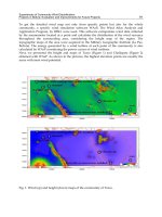
Our group’s main focus at the ETSII-UCLM involved using concentrated solar energy (CSE)
from a Fresnel lens to propose new sintering processes and surface modifications of metallic
components. The aim was to increase the resistance of metallic materials (mainly ferrous
and titanium alloys) to wear, corrosion and oxidation at high temperatures.
The initial studies with CSE at the ETSII-UCLM involved characterising a Fresnel lens with a
diameter of 900 mm, for its use as a solar concentrator (Ferriere et al. 2004). The
characterisation indicated that the lens concentrated direct solar radiation by 2644 times,
which meant that on a clear day with an irradiance of 1kW/m
2
the density of the focal area
would be 264.4 W/cm
2
(Figure 1). This value is much lower than this obtained with other
techniques based on high density beams, but is sufficiently high to carry out a large number
of processes on the materials, and even a fusion of their surfaces.
Measured concentration factors
0
250
500
750
1000
1250
1500
1750
2000
2250
2500
2750
3000
-10-9-8-7-6-5-4-3-2-1012345678910
Radius [mm]
Concentration factor [suns]
z=0
z=-1.5mm
z=+4mm
z=-4mm
z=-6mm
z=+10mm
z=+20mm
z=+30mm
z=+42mm
Fig. 1. Concentration factor of the Fresnel lens
Uses of Concentrated Solar Energy in Materials Science
147
The investigations carried out to date include processes involving the sintering of metallic
alloys, surface treatment of steel and cast irons, cladding of stainless steel and intermetallic
compound, high temperature nitriding of titanium alloys and NiAl intermetallic coating
processing through a SHS reaction (Self-propagating high temperature synthesis). This
research has been carried out in European and national programmes for Access to Large-
Scale Facilities which allowed us to collaborate with the groups of A. J. Vázquez (CENIM-
CSIC, Spain), A. Ferriere (PROMES-CNRS, France) and I. Cañadas (PSA-CIEMAT, Spain)
and to use higher powered solar facilities such as the solar furnaces of PSA and the
PROMES laboratory.
The aim of our research was not just to make inroads on the use of new non-contaminating
technologies, which resolve environmental issues arising from high temperature metallurgy,
but also to increase scientific knowledge about the mechanisms involved in these processes
carried out at high temperatures under non-equilibrium conditions. In the studies we have
conducted to date we have seen a clear activating effect in CSE which results in treatment
times that are shorter, and which add to the efficiency of the process as well as increase in
the quality of the modified surface. This is due to, among other factors, the properties of
solar radiation. The visible solar spectrum extends from the wavelengths between 400 and
700 nm where most metals present greater absorbance, making the processes more energy
efficient. In figure 2 (Pitts et al., 1990) the solar spectrum is compared to the absorbance
values of the different wavelengths of iron and copper. The figure also includes the
wavelength at which certain lasers (those which are habitually used in treating materials)
operate. Here we see the high absorbance of iron for the more energetic wavelengths of the
solar spectrum, and that its absorbance is low at the wavelengths, which the most common
lasers use.
Fig. 2. Solar spectrum (Pitts el al. 1990).
Although the use of solar energy for industrial applications suffers a disadvantage due to its
intermittent nature, it should be noted that according to Gineste (Gineste et al. 1999) in
Odeillo where the Felix Trombe Solar Furnace Centre is located, the peak value of the direct
normal irradiation is 1100 W.m
-2
and it exceeds 700 W.m
-2
during 1600 hours per year and
1000 W.m
-2
during only 200 hours per year. In Ciudad Real, Spain, at latitude 38°, the
availability of the solar energy reported by the Spanish “Instituto Nacional de
Solar Energy
148
Meteorologia” (Font Tullot, 1984), is 11% higher than in Odeillo. Direct solar radiation
measured with a pyrheliometer between 19 June and 31 August, 2009, at the ETSII-UCLM
(Ciudad Real, Spain) registered values higher than 950W.m
-2
for 20% of the days and higher
than 800 W.m
-2
for 97% of the days. The peak value has been attained in this period was 976
W.cm
-2
.
2. Experimental Installations
There are various types of installations for concentrating solar energy. One way of
classifying these installations uses the concentration process as a reference for differentiating
between the different types. In this manner we can distinguish between installations which
use reflection and those which use refraction.
Reflection installations
Reflection installations use mirrors to concentrate solar energy producing one diversion
(direct concentrators) or several diversions (indirect concentrators) of the radiation. The
light is reflected along the entire spectrum of wavelengths, since the mirror does not absorb
anything. Direct concentrators are cylindrical parabolic mirrors and dish parabolic
reflectors. First one uses the heat energy generated mainly to heat the fluids which circulate
through the conduit located in the reflector focal line (Figure 3). Dish parabolic reflector may
be full-surface parabolic concentrators when the entire surface forms an approximately
parabolic shape or multifaceted concentrators composed of various facets arranged in a
parabolic structure that reflects the solar radiation concentrating it in its focal point. The
concentration factor depends on the size, aperture and quality of the surface. The solar
radiation hitting the focal point has a Gaussian distribution and its energy efficiency is very
high due to the high concentration.
Fig. 3. Cylindrical parabolic concentrators at the PSA (Almería Solar Plant).
The indirect concentrators are mainly the solar furnaces. They are systems that take
advantage of the thermal energy generated by the sun for use in applications requiring
medium to high temperatures. They are indirect concentrators that produce several
diversions of the radiation through optical systems specially designed to deflect the incident
light. To deflect the radiation, they use mirrored heliostats, completely flat surfaces that
deflect the direct solar radiation. They are composed of flat reflective facets and have a sun-
Uses of Concentrated Solar Energy in Materials Science
149
tracking system on two axes. Given that a single heliostat is usually totally flat, it does not
concentrate. Therefore, a field of heliostats pointed towards a parabolic concentrator is used
for this purpose (Fig. 4). The power concentrated may be regulated through an attenuator
which adjusts the amount of incident solar light entering.
Fig. 4. Parabolic reflector at the PSA (Almería Solar Plant, Spain)
When the heliostat field is pointed towards a tower (Figure 5) is a direct concentrator
because this system produces only one diversion of the solar radiation.
Fig. 5. Heliostat field with a central tower Solar Two, in Barstow, California
Refraction installations
In these installations solar light travels through a concentrator device that redirects the light
towards its axis. These types of installations absorb part of the wavelength of the solar light.
The most common way of concentrating solar radiation is through the use of converging
lenses, which concentrate radiation in its focal point. Conventional lenses would need to be
too large and too expensive to make them worthwhile for concentrating solar radiation at
the required levels. An alternative to these types of lenses are Fresnel lenses, which serve the
same function, but are much lighter and cheaper.
In Fresnel lenses, the curve of the surface is composed of a series of prisms or facets, in such
a way that each of them refracts the radiation in the same manner as the surface of which
they are a part. This is why a Fresnel lens functions like a conventional lens. The different
Solar Energy
150
polymers used in the manufacture of the lens determine the part of the spectrum in which it
will be effective, and therefore, its applications. The lenses used for concentrating solar
radiation are made of acrylic, rigid vinyl, and polycarbonate. Figure 6 shows how the facets
of a Fresnel lens can be created from a conventional lens.
Fig. 6. Diagram of Fresnel lens
There are several research laboratories that use solar installations to experiment and study
materials at high temperatures (higher than 1000ºC). Table 1 lists the solar installations in
operation across the globe, among which is the installation at ETSII in Ciudad Real.
Country Location Technology Maximum power density (kW/m
2
) Power (kW)
China
Guangzhou
Parabolic
concentrator*
30000***
1.7
Solar Furnace*
16000
1.5
Solar Furnace
10000
1000
Odeillo, CNRS
Solar Furnace
4700
6
France
Odeillo, DGA
Solar Furnace *
6000
45
Germany
Cologne, DLR
Solar Furnace
5200
22
Solar Tower*
1000-2000
3360-7000
Almería, PSA-
CIEMAT
Solar Furnace *
2500
60
Madrid, CENIM-
CSIC
Fresnel lens*
2640
0.6
Spain
Ciudad Real,
UCLM
Fresnel lens* 2640 0.6
Solar Furnace
5000
45
Solar Furnace
4000
15
Switzerland
Villigen, PSI
Parabolic concentrator 4000
70
Ukraine
Ac. of Science
Parabolic concentrator
*
2500
-
Alburquerque, Sandia Solar Furnace *
3000
25
Denver, NREL
Solar Furnace *
2500-20000**
10
USA
Minneapolis, Univ.
Minn.
Solar Furnace
7000
6
Uzbekistan
Tashkent
Solar Furnace
17000
1000
*
Used in the surface modification of materials (papers published), **Used as secondary concentrator, ***Calculated values
Table 1. Solar Installations in the World (Rodríguez, 2000).
Uses of Concentrated Solar Energy in Materials Science
151
2.1 Fresnel lens
The installation is on the roof of the Escuela Técnica Superior de Ingenieros Industriales
building in the UCLM in Ciudad Real (Figure 7). The lens is affixed in a metal structure, and
has a single-axis sun tracking system, connected to a software system in which the different
data generated by the experiment can be collected, such as the values of different
thermocouples. It also has a pyrheliometer which measures the direct incident solar
radiation over the course of the day. The geometry of the lens is circular, with a 900 mm
diameter and centre that is 3,17 mm thick. It is made out of acrylic material, which gives it a
long useful life with low maintenance. The specification of the lens was determined in
previous studies (Ferriere
et al., 2004) which allowed the measurement of the concentration
factor along the focal axis. The focal point of the lens is 757 mm from its centre. This is the
point where the greatest density of energy is reached. The lens concentrates direct solar
energy by up to 2644 times (maximum value at the focal point), which means that for
exposure of 1000 W/m
2
the maximum power density at the focal point is 264 W/cm
2
.
Fig. 7. Fresnel lens at the ETSII (Ciudad Real, Spain).
The density of the solar radiation has a Gaussian distribution in function of the distance
from the focal point within the focal plane. This variation is what allows us to choose the
temperature to be used for the experiment. We can control the energy density of the solar
radiation, adjusting the distance of the sample in the Z axis. (Figure 1).
The Fresnel lens has a reaction chamber where experiments can be carried out in a
controlled atmosphere. The reaction chamber is features a quartz window and a
refrigeration system. In order to measure the temperature a thermocouple is welded to the
bottom of the samples.
2.2 Solar Furnace
The second installation used on a regular basis for generating concentrated solar energy is
the Solar Furnace of Almería Solar Plant (PSA), which belongs to the Centro de
Investigaciones Energéticas, Medioambientales y Tecnológicas (CIEMAT, in English, Centre
of Energy, Environmental and Technological Research). The solar furnace consists of a
heliostat which tracks the sun and reflects the solar rays onto a parabolic mirror. The
furnace of PSA has a heliostat of 160m
2
composed of 28 flat facets which reflect solar rays
Solar Energy
152
perpendicular and parallel to the optic axis of the concentrator and continuously tracks the
sun through a tracking system with two axes (Fig. 8). The mirrors have reflectivity of 90%.
Fig. 8. Heliostat of the PSA solar furnace (Almería Solar Plant, Spain).
The concentrator disk is the main component of the solar furnace (Fig. 9). It concentrates the
incident light of the heliostat, multiplying the radiant energy in the focal zone. Its optic
properties especially affect the distribution of the distribution of the flow on the focal zone.
It is composed of 89 spherical facets covering a total surface area of 98,5 m
2
and with a
reflectivity of 92%. Its focal distance is 7,45 m. The parabolic surface is achieved with
spherically curved facets, distributed along five radii with different curvatures, depending
on their distance from the focal point.
Fig. 9. Concentrator disc of PSA
The attenuator (Fig.10) consists of a set of horizontal louvers that rotate on their axes
regulating the entry of incident solar light hitting the concentrator. The total energy on the
focal zone is proportional to the radiation that passes through the attenuator. The
concentration and distribution of the power density hitting the focal point is key factor in a
solar furnace. The characteristics of the focus with the aperture 100% opened and solar
radiation of 1000 W/m
2
are: peak flux: 3000 kW/m
2
, total power: 58 kW, and a focal
diameter of 25 mm. In this case, the reaction chamber also allows work to take place in a
controlled atmosphere. The chamber also has a quartz window which allows concentrated
Uses of Concentrated Solar Energy in Materials Science
153
solar energy to enter and also allows researchers to monitor the experiment using different
kinds of cameras (digital and IR).
Fig. 10. Attenuator of the solar furnace of PSA (Almería Solar Plant)
2.3 Solar Furnace at PROMES-CNRS
Another solar facility used in our research is the 2kW parabolic solar furnace at the
PROMES-CNRS laboratory (France). The furnace is composed of one heliostat and a
parabolic reflector with a 2 m diameter. The parabolic concentrator has a vertical axis which
allows the samples used in the experiments to rest in a horizontal position without the need
to add more optical diversion systems to the device. Furthermore, given that the parabolic
reflector is the only mirror which is not faceted, it has a higher quality optical properties and
allows a greater concentration factor that that which is obtained with the faceted reflectors.
The focal zone behind the second reflection has a diameter of 15 mm and Gaussian
distribution with the maximum energy at the centre, of 16.000 times the impinging solar
radiation.
3. Surface hardening of steels by martensitic transformation.
Surface quenching is a widely used treatment by the industry to harden and improve wear
resistance of the steel pieces. These types of treatments may be carried out using
conventional heating methods (flame and electromagnetic induction) and high-density
energy beams (laser, electron beams, plasmas, etc.). In all cases the source should be
sufficiently powerful to guarantee that only the surface layer of the piece heats up to a
higher temperature than the austenizing temperature. After cooling off, only the zones
which were previously austenized will have undergone the martensitic transformation that
results in the hardening. In the internal zones, where no microstructural transformations
would have taken place, the mechanical properties would remain unchanged. Therefore, the
end result is pieces that combine a high degree of hardness and toughness and greater
resistance to wear.
Of all the different types of modifications and treatment of materials carried out in the solar
furnaces, surface hardening of ferrous alloys has been the most widely studied. Since the
first study was published by Yu and others in 1982, several research groups have been
exploring the possibilities of this process (Maiboroda et al., 1986; Stanley et al., 1990;
Solar Energy
154
Ferriere, 1999). This first study showed how the high concentrations obtained in the solar
focal area of a parabolic concentrator with a 1.5 m diameter produced self-quenching in a
surface zone 0.5 mm deep and 5 mm in diameter in a steel piece after a second of exposure
to solar radiation (Yu et al. 1982). In addition, the initial investigations show how localised
treatments can be carried out on industrial pieces with complicated geometries by moving
the sample with respect to the focal area of the furnace (Yu et. al, 1983) (Zong et al., 1986).
In Europe, the first experiments were carried out in the 1990’s by a group led by Prof.
Vázquez of CENIM-CSIC (Spain). The research carried out was highly important because it
demonstrated the viability of using the different types of solar facilities available at the
Almeria Solar Plant to surface harden steel pieces. The experiments were carried out using
the SSPS-CRS facility, which comprises a heliostat field and a central tower (Rodríguez et al.,
1995), and the Parabolic Solar Furnace which comprises a group of heliostats and a faceted
parabolic concentrator (Rodríguez et al., 1997). The results indicated that under the best
conditions of direct solar radiation it was possible to obtain homogeneous quenched layers
between 1 and 3 mm thick with heating times of between 30 and 60 seconds. The study was
completed using a Fresnel lens with a 900 mm diameter which was available at the Instituto
de Energías Renovables of CIEMAT in Madrid (Rodríguez et al., 1994). The study added to
knowledge regarding the advantages and limitations of each one of the facilities. With the
facility comprising the central tower and the heliostat field, a surface of 10 cm
2
can be
quenched, much more than what is possible using other techniques and types of solar
facilities. But with the PSA Solar Furnace and the Fresnel lens it is possible to obtain greater
energy densities in the focal area (250-300W.cm
-2
) depending on the incident solar radiation,
which allows for self-quenching in steel alloys.
Using the ETSII-UCLM Fresnel lens described above, our group carried out research on
surface hardening steels and cast iron, with the ultimate aim being the discovery of
industrial applications for this process. The first experiments consisted of surface hardening
through martensitic transformation of three types of steel and a nodular cast iron piece.
In all cases the influence on the treatment of the different variables was assessed: heating
rate, maximum temperature reached, cooling medium, size of the treated pieces (diameters:
10 and 16 mm, height: 10 and 15 mm). The study entailed determining the microstructural
transformations, the profile of the hardness and the depth of the quenching (total and
conventional).
Figure 11 shows the results obtained using a sample with a 10 mm diameter and 10 mm high
of tool steel AISI 02, where the homogeneous quenching can be seen along the entire diameter
of the test sample, as well as the surface hardness values obtained. Figure 12 shows the results
obtained after carrying out a surface quenching treatment of a nodular cast iron piece.
In addition, studies were carried out to assess the possibility of carrying out localised
treatments on the surfaces of pieces that required greater hardness and resistance to wear.
The microhardness curves in Figure 13 show the effect of heating time on the diameter of
the quenching zone of a 1 mm plate of martensitic stainless steel AISI 420.
Due to the fact that the heating conditions depend on the direct solar radiation it is
necessary to have a predictive tool that can set the treatment conditions in function of the
direct solar radiation present. To this end, a finite element model (FEM) (Serna & Rodríguez,
2004) has been developed which gives the distribution of the temperatures of the pieces
during treatment. The model takes into account both the Gaussian distribution of the energy
density in the focal area and the variation in the temperature of the phase transformation of
the steel in function of heating speed.
Uses of Concentrated Solar Energy in Materials Science
155
0
200
400
600
800
1000
012345678910
Depth (mm)
HV500gf
e1
c
e2
Fig. 11. Surface quenching of 10 mm high test sample after 45 seconds of heating.
0
100
200
300
400
500
600
700
800
900
012345678910
Depth (mm)
HV 0.5
Fig. 12. Microhardness profile of a nodular cast iron piece heated for 40 seconds in the focal
area of a Fresnel lens.
0
200
400
600
800
-9 -8 -7 -6 -5 -4 -3 -2 -1 0 1 2 3 4 5 6 7 8 9 10
Distance (mm)
HV500gf
t = 9 s t = 7 s t = 6 s
Fig. 13. Influence of heating time on the diameter of the quenching zone of a 1 mm thick
plate of martensitic stainless steel.
The size of the focal area of the lens limits the possible application to small pieces (surface
areas of between 50 mm
2
and 100 mm
2
, depending on the maximum required temperature),
or to localised treatments on larger sized pieces. Obviously treatments and modifications of
Solar Energy
156
metallic materials with small surface areas are carried out on an industrial scale for a large
number of applications, but there are few bibliographic references concerning specific
applications for localised treatments using solar facilities.
4. Hardening through surface melting of cast iron
The surface melting treatment of grey cast iron leads to the formation of superficial layers
with excellent resistance to wear. The rapid cooling from the melted state gives rise to the
formation of extremely hard white cast iron with great resistance to wear. Given this profile,
this type of melting process is an excellent candidate for machine pieces that are subject to
movement and vibrations and which are in contact with other components. At present,
industrial processes are using various heating techniques such as TIG, electromagnetic
induction, and electron or laser beams, among others, in order to carry out this type of
surface melting treatment.
Recent experiments at the ETSII show how it is possible to use concentrated solar energy to
carry out at the melting treatments on industrial cast iron pieces. The study to date has
centred on hardening through surface melting and quenching of camshafts used in the
automobile industry and manufactured with grey cast iron. In order to carry out the
treatment a specimen support device was created which allowed the cam to spin in the focal
plane of the Fresnel lens. The results obtained are compared with those of a camshaft
manufactured using conventional industrial processes (TIG). Figure 14 shows the hardness
profiles of the hardened area of the two pieces, one that was hardened with concentrated
solar energy, and the other through TIG (both made of the same cast iron). The graph shows
us that the camshaft treated with CSE attained a far greater hardness and had a smaller heat
affected zone. In addition, the surface finishing attained from the solar treatment is better
than that obtained after treatment with TIG, which would translate into lower costs (Figure
15). Current research is focused on automating the system in such a way that the entire
camshaft may be treated continuously.
0
100
200
300
400
500
600
700
800
900
1000
012345678910
Depth (mm)
HV 500gf
TIG
CSE
Fig. 14. Hardness profile of samples treated by TIG vs. CSE
Uses of Concentrated Solar Energy in Materials Science
157
Fig. 15. Surface finishing after TIG (A) or CSE (B) treatment.
5. Cladding of stainless steel and intermetallic compounds onto steel
substrates.
There are many types of surface modification techniques that aim to improve the corrosion
and oxidation resistance. One widely studied surface modification technique is cladding. A
material with the desired properties is melted on the base metal by means of an energy
beam. The mixture between the coating material and the base metal must be as small as
possible in order to guarantee the original properties of the coating. In this way it is possible
to use a cheap structural material and to coat it with another that confers its surface the
desired properties.
The literature contains several references that describe the use of different solar installations
to obtain cladding coatings. In the USA Pitts et al., (Pitts et al., 1990) obtained cladding
coatings on stainless steel. Subsequently, in Spain, Fernandez et al. performed Ni cladding
on steel at the Almeria Solar Plant (Fernandez et al., 1998).
We have studied the possibility of obtaining cladding coatings using the parabolic solar
furnace of the PROMES-CNRS laboratory previously described (Ferriere et al., 2006). The
high energy densities obtained with the solar beam allowed stainless steel and NiAl to be
cladding coated through rapid melting-solidification of powders pre-deposited on carbon
steel samples. Coatings have been processed in tracks by scanning the concentrated solar
beam across the specimen surface with the aim of modifying larger areas than are possible
with a stationary treatment. The scanning process is performed by moving the specimen at a
controlled speed that depends on the direct solar irradiation. The coatings processed are
homogeneous, adherent and have low porosity. In addition, the formation of dendritic
microstructures results in increased electrochemical corrosion resistance.
The fundamental disadvantage that has been encountered in this research is the difficulty of
achieving a coating with a composition close to that of the initial powder while at the same
time guaranteeing good adhesion to the substrate. A possible solution to this problem
consists of using a powder injector (nozzle), in order to carry out the process in one single
step as is habitual in the case of laser cladding.
6. Salt-bath nitriding of steels.
It is possible to harden the surface of different kind of steels using a novel technology that
combines the use of non-contaminant salts with the activator effect of the concentrated solar
energy. Groundbreaking research (Shen et al. 2006a), (Shen et al. 2006b) has studied the
(
A
)
(
B
)
Solar Energy
158
possibility of the substituting highly contaminating cyanide salts used in liquid nitriding for
common salt KNO
3
, which avoids this high toxicity. In line with this innovative research
vector, our research has tried to explain the different mechanisms through which nitrogen
from the salt is introduced into the steel matrix, thereby achieving the desired surface
hardening. In addition, we are researching the use of concentrated solar power as an energy
source (Herranz & Rodríguez 2008). The experiments were carried out using the Fresnel lens
at the ETSII and the solar furnace at the Almeria Solar Plant. The results were compared to
those that were obtained using an electric muffle furnace. Steels with a wide range of
characteristics were selected for the research. One was a relatively cheap, low alloy steel
with low carbon content, the AISI 1042. The other steel used was the high-speed tool steel
M2 which is commonly used in industry. These two types of steel were used to highlight the
different characteristics made evident during the nitriding process. The treatment resulted
in the surface hardening of the two steels through the interstitial diffusion of nitrogen in the
steel network and in some samples nitrides were formed. The exhaustive study of these
results interprets the nitriding mechanism that occurred in each steel. In addition, the
traditional treatment times were reduced to a large degree. This evidences the viability of
this nitriding process using concentrated solar energy (CSE).
The maximum surface hardening of AISI 1042, which is not a conventional steel to use for
nitriding, increased 61% with respect to its nominal value. Nitrided M2 steel attained a
surface hardness of 900HK (Herranz & Rodríguez, 2007) (Fig. 16).
300
400
500
600
700
800
900
1000
0 200 400 600 800 1000 1200 1400
Depth (µm)
Hardness (Hk
100g
)
15 min.
Fig. 16. Hardness profile obtained in a nitrided M2 piece using a treatment of nitrate salts
during 15 minutes using concentrated solar energy.
The diffusion layer obtained in both steels submitted to the nitriding process in KNO
3
salts
are greater than those obtained in earlier experiments with other nitriding methods.
Therefore, the maximum diffusion layer obtained in AISI 1042 steel has an approximate
thickness of 1300 μm and 550 μm in the M2 steel.
The other fundamental conclusion of our research is that concentrated solar energy activates
the process, notably reducing the treatment times. Treatment time was greatly reduced in
the treatment of the AISI 1042 using the Fresnel lens. Only 35 minutes was needed, versus
the 90 minutes needed in a muffle furnace for the same treatment. This reduction is
especially notable if we compare it with other conventional nitriding methods, such as with
plasma, which requires 3 hours. In the case of the nitriding of the M2 sample, the reduction
in treatment time using concentrated solar energy is more significant. With a Fresnel lens,
only 60 minutes was needed (a muffle furnace requires 3 hours). The reduction was even
Uses of Concentrated Solar Energy in Materials Science
159
more remarkable in the case of PSA (Almería Solar Plant), which only needed 15 minutes of
treatment.
The nitriding of low alloy steel characterised by its free interstices, such as AISI 1042 steel,
occurred primarily through the interstitial diffusion of nitrogen coming from the salts
towards the interior part of the steel piece. In the nitriding mechanism for the M2 high-
speed steel, high alloy tool steel, part of the nitrogen originating from the salts was
introduced through interstitial diffusion towards the interior of the steel, while another part
formed iron nitrides and/or iron alloy nitrides. These compounds contribute to the surface
hardness.
7. Gas nitriding of titanium alloys.
In recent years, Ti alloys have been widely studied due to their properties: low density, high
melting point, good mechanical properties, high corrosion and oxidation resistance and
biocompatibility. These properties explain their appeal to the aerospace industry and as
biomaterials. However their use in these fields remains limited because of their poor
tribological properties. These problems can be overcome by changing the nature of the
surface using thermochemical treatments. In the case of the Ti alloys the most widely
surface treatment used is the nitriding. There are different ways to nitride the surface. One
of the most frequently method is the gas nitriding.
Gas nitriding is a diffusion process that involves heating the surface at high temperatures
for a long time. In most cases, the equipment is expensive both start up and to maintenance.
For this reason there is significant interest in developing more economic and energy efficient
systems. Nitrogen is soluble in titanium and forms a interstitial solid solution, resulting in a
hardening by solid solution caused by deformation in the crystalline network. It is
important to assure that no oxygen is present in the process in order to prevent the
formation of TiO
2
oxides on the piece. The types of dissolution of nitrogen in the titanium
may be seen in the equilibrium diagram of the Ti-N system (Fig. 17) (Wriedt &
Fig. 17. Phase diagram Ti-N. (Wriedt & Murray, 1987).
Solar Energy
160
Murray, 1987). We observe a solid phase α solution with a high degree of solubility of
nitrogen (from 0 to 8% in weight) which remains stabilised at high temperatures. At levels of
over 8% of nitrogen (in weight) the alpha phase saturates and intermetallic compounds are
obtained, such as Ti
2
N and TiN. These nitrides have very high hardness values and give the
maximum hardness to the surface layer.
Existing studies indicate that there are some problems related to the use of this treatment in
the traditional manner, which uses electric furnaces, such as the need for long treatment
times of over 16 hours and at high temperatures of over 1000º C. In contrast, the use of
concentrated solar energy obtains high temperatures at high heating and cooling rates (that
allow the creation of non-equilibrium microstructures) with short treatment times. We have
found that due to the photoactivation capability of the concentrated solar energy, the
duration of the process can be greatly reduced. To our best knowledge, the study by
Vazquez in 1999 is the only significant research that has been conducted in this area
(Sánchez Olías et al, 1999).
Our research focuses on the gas nitriding of the Ti6Al4V alloy. The base material has a
biphasic microstructure (α+β) and a hardness of 400 HK. Tests involved applying heat of
between 1000º C and 1200ºC for between 5 to 30 min. In order to measure the temperature, a
thermocouple was welded to the bottom of the samples and the samples were situated in
the reaction chamber where the nitrogen atmosphere was controlled (Fig. 18). The chamber
has a quartz window which permits the entrance of the concentrated solar energy and also it
allows to observe and record the experiment by different kind of cameras (digital and IR).
(A)
(B)
(C)
(D)
Fig. 18. (A) The samples in the reaction chamber. (B) Sample with the thermocouple. (C)
Digital record of the experiment in the solar furnace. (D) Direct observation of the
experiment in the Fresnel lens.
The results obtained indicate that with the solar facilities significant hardening can be
obtained from processes carried out at 1050ºC for only 5 minutes. In the microstructure we
observed a layer of a different kind of nitrides identified by X-Ray diffraction that increase
Uses of Concentrated Solar Energy in Materials Science
161
the hardness of the samples. In addition, nitride layer growth occurred where the treatment
time was increased. Besides the hardening due to the formation of nitrides, we also
observed a deeper hardening due to the interstitial solid solution of the nitrogen in titanium
matrix. As shown in Figure 19 we have been able to distinguish between the different
hardened layers. The first is a compound layer, then a diffusion layer that can achieve 400
μm for the longest treatment times and then, the base material.
Fig. 19. Microstructure of sample nitrided during 10 min at 1050ºC using concentrated solar
energy.
The compound layer was identified through X-ray diffraction as Ti
2
N, which was the
maximum hardness detected (1200HK). The presence of TiN was also detected, but its
density was so scant that it was impossible to measure its hardness. In addition, it was
evident that the process did not result in a completely continuous layer at this temperature.
Compound layers grew considerably as the treatment temperature rose or time was
increased. These layers covered the pieces more homogeneously and the diffusion layer was
thicker. As shown in figure 20, at 1200ºC, after 15 minutes of treatment, two totally
continuous layers were formed. According to the X-ray diffraction, the exterior layer was
TiN, and the second layer was Ti
2
N. Under these parameters, the TiN layer had a maximum
hardness of 2600 HK.
Fig. 20. Microhardness evolution in the samples nitrided during 15 min at 1200ºC using CSE
Com
p
ound la
y
er Ti
2
N
Diffusion la
y
er
Base Material
0 200 400 600 800 1000 1200
200
400
600
800
1000
1200
1400
1600
1800
2000
2200
2400
2600
Depth (μm)
Microhardness (HK
0.05
)
T = 1200ºC
15 min
Solar Energy
162
After these experiments, wear resistance was evaluated using a pin on a disc test machine.
The tests were made in dry conditions against a ball of aluminium oxide. In the case of the
samples nitrided in the Fresnel lens, the samples showed a lower coefficient than the as-
received material, with a friction coefficient of 0.5, showing values of 0.2 for treatment of
only 15 minutes at 1200ºC. In regard to the wear rate, compared with the base material it
decreased by two orders of magnitude after only 15 minutes of treatment. The track width
was decreased from 1.890 μm in the Ti6Al4V alloy to 180 μm in the nitrided sample. These
experiments show the significant potential of this new modification process consisting of
gas nitriding with concentrated solar energy. The great reduction of nitriding time can be
explained by the photo-activation effect of the concentrated solar energy.
8. Solar sintering of metallic powders.
The feasibility of using a solar furnace for the sintering-consolidation of green parts
previously obtained by compaction has been tested. The use of solar furnaces allows
materials to be processed at much higher heating and/or cooling rates, which results in
better mechanical properties and a quite significant reduction in the total cycle time. The
demand for faster and less expensive techniques for processing pieces has resulted in the
development of high energy techniques for manufacturing prototypes and carrying out
short series tooling, such as laser sintering (Asgharzadeh & Simchi 2005) and capacitor
discharge sintering (CDS) (Fais & Maizza 2008). The use of these faster technologies has
usually resulted in finer microstructures, while improving mechanical properties and the
sintering window. In the search for new sintering systems that overcome this issue, the use
of concentrated solar energy (CSE) appears to be an interesting candidate. The CSE is clean,
renewable and pollutant free. In spite of its apparent limitations for industrial applications,
due to the unpredictable availability of solar radiation, CSE shows a clear activator effect in
different processes (Herranz & Rodriguez 2007); (Herranz & Rodríguez 2008).
Earlier research focused on studying the technique’s viability for manufacturing WC-10%Co
ceramic components and complex ceramics (cordierite) (Guerra Rosa et al., 2002); (Almeida
Costa Oliveira et al., 2005); (Cruz Fernandes et al., 2000) using concentrated solar energy.
These studies have proven that it is possible to use CSE to obtain pieces with very similar
characteristics to those obtained using conventional electric furnaces. In the same line, a
preliminary study of a copper system has also been published (Cañadas et al., 2005). The
results of these studies all share two characteristics: the good mechanical properties
obtained, and the major reduction in total treatment time required.
We have assessed the feasibility of concentrated solar energy for sintering-consolidation of
green parts previously obtained using compacted metallic powder. The experiments were
carried out using the two facilities described in this chapter; a parabolic solar furnace of the
Almeria Solar Plant (PSA) and a Fresnel lens at the Castilla-La Mancha University (ETSII-
UCLM). The research focused on the microstructural evolution of the samples treated in
both facilities. In this work we compared the results of the sintering process in a N
2
-H
2
atmosphere using concentrated solar energy with the conventional furnace results. The main
materials we worked with were M2 tool steel, copper-based alloys (such as bronze), and
carbon-based steels with alloys such as Astalloy. The energy density obtained in the focal
area of the solar furnace or in the focal area of the Fresnel lens is high enough to raise the
sample’s temperature to sintering levels. To process the samples at different sintering
temperatures, experiments were conducted changing the focal length. The samples were
Uses of Concentrated Solar Energy in Materials Science
163
then heated up to the maximum temperature for 30 minutes. The total duration of the
sintering process (including the heating and the cooling) was less than 70 minutes in all
cases. In order to compare results, the sintering experiments were carried out in a
conventional tubular furnace in the same atmosphere, applying conventional sintering
temperatures for 30 min (dwell time). (Figure 21).
Fig. 21. Cycle in the conventional furnace and in the solar installations comparing the
duration of the sintering processes.
We made several interesting findings. For example, we found that the high-speed M2 steel
showed major differences in the microstructures obtained, depending on the sintering
process used. The microstructure of M2 sintered in a conventional furnace in N
2
-H
2
atmosphere at the optimum sintering temperature, around 1290ºC, presented a ferrite
matrix with some retained austenite, Figure 22. We also observed a significant amount of
homogeneously distributed bright rounded M6C carbides (identified as rich in W and Mo).
The sintering atmosphere has an important influence on the development of the
microstructure because the nitrogen content of the steel slightly increases the optimum
sintering temperature. The increase in nitrogen content has no effect on the M
6
C carbides
but, as pointed out in a previous study by Jauregi (Jauregi et al 1992), the MC carbides (rich
in V) transform into MX carbonitrides that appear with grey contrast inside the grains and at
the grain boundaries. In the conventional furnace an increase of the temperature up to 1300ºC
produces an over-sintered microstructure in which a continuous M
6
C carbides film around the
grain boundaries is observed. The EDX analysis revealed that at high temperatures the MX
carbonitrides were able to transform themselves into black-contrast square VN nitrides
detected at the grain boundaries. The maximum hardness achieved was 550 HV.
In the case of the samples treated in the PSA solar furnace and with the Fresnel lens, we
observed a completed densification. The most remarkable discovery was that for the
processes carried out using concentrated solar energy, the process activated at lower
temperatures. Figure 23 shows the densification process and the microhardness evaluation.
The feasibility of the sintering process using CSE was demonstrated as the parts displayed
well-defined necks and greatly reduced porosity.
0 100200300400500
0
200
400
600
800
1000
1200
1400
Temperature (ºC)
Time (min)
Conventional Furnace
Solar Furnace
Fresnel lens
Solar Energy
164
Fig. 22. SEM micrograph of M2 sample sintered at (A) 1290ºC and (B)1300ºC in nitrogen-
hydrogen atmosphere in the conventional furnace.
Fig. 23. Densification process of the samples treated in the solar furnace of PSA.
As can be seen in the Fig. 24 (A), at only 1115 ºC, some rounded and isolated porosity was
observed and a homogeneous distribution of carbides indicates that the sintering process
really took place. Microhardness measurements indicate that, at this temperature, the
distribution of the carbides was homogeneous and the porosity had disappeared in most of
the sample. The microhardness achieved values similar to those of the samples sintered in
the conventional furnace (580 HV). The microstructure obtained at this temperature was the
(A)
(B)
1100 1150 1200 1250 1300
88
90
92
94
96
98
100
Relative Densification
Microhardness
Sintering Temperature (ºC)
Relative Densification (%)
550
600
650
700
750
800
850
900
950
Microhardness (HV)
Uses of Concentrated Solar Energy in Materials Science
165
same as that obtained at 1260ºC in the electric furnace. When the sintering temperature was
increased to 1125 ºC, Fig. 24 (B), full density was achieved and there was a sharp increase in
grain growth. In addition, massive bright carbide segregation was observed, as well as
formations corresponding to the eutectic phase, but only in some areas. Most of the grain
boundaries did not show carbides, indicating that they underwent a partial dissolution
during the sintering process. Based on EDX analysis, we ascertained that the increase of
nitrogen in the matrix due to the sintering gas allowed the formation of VN nitrides both
inside the particles and along the grain boundaries. In spite of the grain growth, this
sample’s hardness was over 900 HV.
Fig. 24. SEM micrograph of M2 sample sintered at (A) 1115ºC and (B)1125ºC in nitrogen-
hydrogen atmosphere in the solar furnace.
As part of our efforts to explain these results, we carried out several preliminary studies
using transmission electron microscopy (TEM). Initial analysis corroborated that the high
velocities obtained had caused the formation of vanadium-rich nanometric particles on the
order of 400 nanometres, which in certain cases may be complex and contain small 30
nanometre particles rich in other steel alloy elements (W, Mo and V) in their interior. The
presence of these particles would explain the high hardness values obtained. However, it
would be necessary to carry out a more in depth analysis to fully understand the mechanism
responsible for the formation of these small particles.
The results obtained using the Fresnel lens are similar. In figure 25, the large darker particles
(identified as VN) stand out in particular and are precipitated at the grain boundaries or
close to them, with an average size of 2 µm. In addition, there are a large number of small
nanometric particles dispersed throughout the matrix, which once again explain the high
hardness values obtained, despite the rapid growth observed in the grain. Lighter contrast
carbides (rich in W and Mo) are concentrated at the grain boundaries while larger particles
are distributed homogenously throughout the sample. In addition, eutectic M
6
C “fishbone”
structures can also be observed at some of the grain boundaries.
We would highlight that certain pieces were totally densified at lower temperatures, 150ºC
lower than with a conventional furnace. Almost full density was attained after 75 minutes in
the PSA and after 50 minutes in the Fresnel lens installation, with higher hardness than the
conventional microstructures (760-900 HV). The higher heating and cooling rates could
explain these results, since the equilibrium phase diagram changes with the heating rate and
in these new heating conditions new sintering mechanisms have occurred. The
microstructure and the hardness measurements were similar to those found in the M2
system treated by selective laser sintering (Niu & Chang, 2000).
(A)
(B)
Solar Energy
166
M
6
C
VN
Fe, α
Fig. 25. SEM micrograph of M2 sample sintered in nitrogen-hydrogen atmosphere in the
Fresnel lens.
9. Processing of intermetallic coatings through a self-propagating high
temperature synthesis process initiated with solar energy (SHS-CSE).
The intermetallic compound NiAl shows attractive properties such as low density, high
melting temperatures, high thermal conductivity and good mechanical behaviour at high
temperature. Although its low ductility at room temperature could limit its applications as
structural material its good tribological properties and excellent oxidation resistance justify
its use as a protective coating for metallic components. Cladding, and self-propagating high
temperature synthesis (SHS) processes are among the other techniques used currently for
coating this intermetallic compound (Matsuura et al., 2000).
SHS is an energy efficient method to process advanced ceramic materials and intermetallic
compounds. Discovered by Merzhanov in 1967 (Merzhanov, 1967) it uses the highly
exothermic properties of a chemical reaction that are sustained and propagated through a
mix of reactants (usually in powder form) in the form of a combustion wave. The energy
savings and the economic benefits obtained from SHS are widely acknowledged (see, for
example, Deevi & Sikka, 1997).
Concentrated solar energy was first used for the coating process using an SHS reaction in a
study by G.P. Rodríguez et al. (Rodríguez et al., 1999) in which they were able to process
coatings of NiAl on circular samples with a diameter of 30 mm, using a Fresnel lens. The
solar energy triggered a exothermic reaction between the Ni and the Al at ignition
temperature (the melting point of Al). The heat released by this reaction was transferred
through conduction to the adjacent zones, initiating the reaction in these zones again, for
which reason the reaction is considered self-propagated. The heat released (combined with
that of the solar beam) melts the compound obtained, resulting in a dense non-sinterized
material. This process was optimised by Sierra and others (Sierra & Vázquez, 2005), where
the adherence of the coating to the substrate was improved through the electrodeposition of
a nickel layer prior to the treatment. The study carried out with the Fresnel lens of the ETSII-
UCLM used elemental Ni and Al powders and resulted in adherent NiAl coatings over cast
iron. In order to increase the adherence and decrease the porosity that frequently occurs in
coating processes that use SHS, a preheating system was designed for the substrate, which
also uses solar power.
Uses of Concentrated Solar Energy in Materials Science
167
In addition, the 2 kW solar furnace at the PROMES-CNRS laboratory was used (under the
collaboration framework between CENIM-CSIC, PROMES-CNRS and ETSII-UCLM) to
obtain NiAl coatings in track forms, processing larger surface areas than those that were
processed using the Fresnel lens (Sánchez Bautista et al., 2006). The scanning method is
similar to that used when coating surfaces using solar cladding, although the beam-sample
interaction times are lower (due to faster movement of the sample). The main difficulty
arising when coating surfaces using a solar assisted SHS process lies in controlling the
process variables so that the resultant coating is of low porosity, high adherence and with
the required chemical composition. A possible solution may involve preheating the
substrate. Another challenge is to optimise the processing of coatings over large areas.
10. Conclusions
Concentrated solar energy (CSE) represents an alternative to other types of energy beams
for treating and modifying the surfaces of metallic materials. The research conducted by the
Metallic Materials group of ETSII-UCLM (Spain) is interesting for two reasons. First, it is
breaking new ground in the use of new non-contaminating and environmentally acceptable
technologies for processes involving the surface modification of metallic materials at high
temperatures. Second, it is increasing scientific knowledge about the mechanisms involved
when processing materials at high temperatures under non-equilibrium conditions. In the
studies carried out to date, it has been observed that CSE has a clear activator effect, which
results both in shorter treatment times and therefore, in increased processing efficiency, and
in improved quality of the modified surface.
For high-temperature processes, concentrated solar energy has shown to be highly energy
efficient and also competitive in terms of cost. It is especially suitable for countries such as
Spain, which has a high number of sunny days per year. Going forward, one of the main
challenges for the scientific community will be to develop industrial applications for solar
technology, especially in the current context, where energy-efficiency and environmental
preservation have become top social priorities.
11. References
Almeida Costa Oliveira, F.; Shohoji, N. ; Cruz Fernandes, J. & Guerra Rosa, L. (2005). Solar
sintering of cordierite-based ceramics at low temperaturas, Solar Energy, 78, 3, 351-
361 ISSN 0038-092X
Asgharzadeh, H. & Simchi A. (2005). Effect of sintering atmosphere and carbon content on
the densification and microstructure of laser-sintered M2 high-speed steel powder,
Materials Science and Engineering A, 403, 290-298, ISSN 0921-5093
Cañadas, I.; Martínez, D.; Rodríguez, J. & Gallardo, J.M. (2005). Viabilidad del uso de la
radiación solar concentrada al proceso de sinterización de cobre, Rev. Metal. Madrid,
Vol. Extr. 165-169, ISSN 0034-8570
Chaudron, G.& Trombe, F. (1973). Les hautes températures et leurs utilisations en physique et en
chimie, Masson et Cie, ISBN 2225360698; Paris, France.
Cruz Fernandes, J.; Amaral, P.M.; Guerra Rosa, L. & Shohoji, N. (2000). Weibull statistical
analysis of flexure breaking performance for alumina ceramic disks sintered by
solar radiation heating, Ceram. Int. 26, 203–206 ISSN 0272-8842