Báo cáo hóa học: " Research Article On the Evaluation of MB-OFDM UWB Interference Effects on a WiMAX Receiver" potx
Bạn đang xem bản rút gọn của tài liệu. Xem và tải ngay bản đầy đủ của tài liệu tại đây (2.1 MB, 14 trang )
Hindawi Publishing Corporation
EURASIP Journal on Wireless Communications and Networking
Volume 2010, Article ID 414927, 14 pages
doi:10.1155/2010/414927
Research Article
On the Evaluation of MB-OFDM UWB Interference Effects o n
aWiMAXReceiver
Eduardo Cano, Alberto Rabbachin, Detlef Fuehrer, and Joaquim Fortuny
Institute for the Protection and Security of the Citizen, Joint Research Centre, European Commission, Ispra, 21027 Varese, Italy
Correspondence should be addressed to Eduardo Cano,
Received 1 November 2009; Revised 20 April 2010; Accepted 6 July 2010
Academic Editor: Yan Xin
Copyright © 2010 Eduardo Cano et al. This is an open access article distributed under the Creative Commons Attribution License,
which permits unrestricted use, distribution, and reproduction in any medium, provided the original work is properly cited.
The European Commission has recently adopted specific power spectral density masks for ultra wideband (UWB) devices, with
detect and avoid capabilities, for coexistence with licensed standards. Under these regulations, a novel approach for analyzing the
UWB interference effects on the WiMAX downlink is provided in this paper by means of a novel theoretical computation of the bit
error rate (BER), simulation results, and measurements in a conducted modality. New analytical BER expressions for both uncoded
and coded WiMAX systems, impaired by a single multiband-OFDM (MB-OFDM) UWB interference signal, are obtained in this
paper for a Rayleigh fading channel. The BER is expressed in terms of the characteristic function of the interference signal. The
maximum permissible interference levels and the signal-to-interference (SIR) values, which allow the UWB interference effects to
be considered negligible, are estimated in this paper from simulation and measurement results. The analysis considers a WiMAX
receiver operating at its minimum sensitivity level. The BER, the symbol error probability (SEP), and the error vector magnitude
(EVM) of the WiMAX link are the metrics employed to character ize the interference effects for both frequency hopping and
nonfrequency hopping UWB interferers.
1. Introduction
The demand for reliable, fast, and low-cost data com-
munications services for all types of wireless applications
and environments has increased rapidly in the last few
years. Often, different types of wireless networks coexist in
the same area and share the communications channel. In
such situations, if appropriate mitigation techniques are not
applied, wireless signals coming from different sources could
interfere with each other causing a considerable degradation
in system performance. The coexistence scenar io analyzed in
this work corresponds to the case of a sing le ultra w ideband
(UWB) transmitter operating at the same frequency band
as a WiMAX receiver. UWB technology is established as a
viable candidate for future w ireless personal area networks
(WPANs) that require the processing of information with
low-power sources at very high speeds across short distances
(order of 10 m) [ 1]. Alternatively, WiMAX systems, which
are derived from the IEEE 802.16 air interface standards [2,
3], allow for high-speed broadband connectivity in cellular
point-to-multipoint wireless metropolitan area networks
(WMAN) of wider range (order of 5 Km).
The Federal Communications Commission (FCC) in the
US approved the use of UWB technology for commercial
applications under part 15 of its regulations in Februar y 2002
[4]. The FCC report and order defined UWB as a signal with
bandwidth to central frequency ratio greater than 20% or,
alternatively, w ith a
−10 dB bandwidth exceeding 500 MHz
in the frequency range of 3.1–10.6 GHz. The FCC permits
UWB devices to operate on an unlicensed basis following
restrictive power spectral masks for both indoor and outdoor
environments. A maximum mean effective isotropic radi-
ated power (EIRP) spectral density of
−41.3 dBm/MHz is
established over all the 7.5 GHz operation bandwidth. Under
these initial conditions, UWB devices can cause harmful
interference to primary services operating simultaneously
in their vicinity. This is the scenario under which WiMAX
systems operate at 3.5 GHz in Europe.
On February 21, 2007 the European Commission issued
its Decision 2007/131/EC, which regulates the use of radio
spectrum for equipment using UWB in a harmonized
manner in the European Community [5]. The European
regulations for UWB are based on the former FCC indoor
mask with considerable restrictions on the EIRP levels
2 EURASIP Journal on Wireless Communications and Networking
−80
−70
−60
−50
−40
−90
FCC indoor
FCC outdoor
BWA services
9876543210111
f (GHz)
Mean EIRP (dBm/MHz)
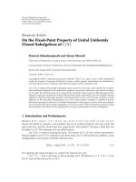
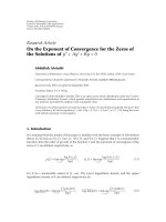
EC/DEC/(06)04 maximum permitted EIRP
Figure 1: EIRP masks for FCC indoor, FCC outdoor, and EU
regulations.
in specific bands as illustrated in Figure 1.Inparticular,
detect and avoid (DAA) or low duty cycle (LDC) mitigation
techniques are imposed in the band 3.1–4.8 GHz to protect
licensed broadband wireless access (BWA) services [6]. The
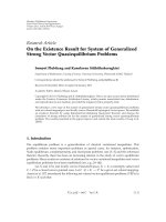
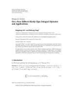
DAA mechanism is based on the definition of three zones
for which an appropriate maximum mean EIRP spectral
density is authorized. In DAA mode, the UWB device
detects and estimates the power level of the WiMAX service
and dynamically adapts its EIRP level depending on the
zone of operation. This coexistence operation is reflected in
Figure 2, in which the power threshold levels are between
zones
−38 dBm and −61 dBm. The maximum mean EIRP
spectral density levels are
−41.3 dBm/MHz, −65 dBm/MHz
and
−80 dBm/MHz for zones 1, 2, and 3, respectively.
The objective of this work is to evaluate the interference
effects caused by a UWB tr ansmitter, compliant with the EU
DAA regulations and which follows the multiband OFDM
(MB-OFDM) approach [7], on a WiMAX receiver by means
of theoretical analysis, simulations, and experimental results.
Several studies that evaluate the coexistence between
WiMAX systems and UWB devices with DAA functionality
have been carried out in the literature [8–14]. However, there
is a lack of published work that validates the theoretical
findings in practical implementations and viceversa. In an
analytical approach, novel expressions for the bit error rate
(BER) for uncoded/coded WiMAX systems are presented
in this paper, based on the statistical characterization of
the MB-OFDM UWB interference. A similar approach for
obtaining the BER in coded systems can be found in
[15, 16] and for uncoded systems in [17]. In contrast
to the aforementioned works, a novel closed form of the
BER for the WiMAX link in the presence of Rayleigh
fading is obtained by means of computing the characteristic
function of the MB-OFDM interference signal without using
numerical integration methods. Furthermore, the analytical
BER functions obtained in this paper are expressed in terms
of the maximum allowable signal-to-interference (SIR) levels
measured at the input of the WiMAX victim receiver. In the
Detection threshold
−61 dBm
Detection threshold
−38 dBm
UWB @
−65 dBm/MHz
UWB @
−80 dBm/MHz
UWB @
−41.3 dBm/MHz
WiMAX terminal
protection requirement
−80 dBm/MHz @ 36 cm
Zone 1
Zone 2
Zone 3
Figure 2: Protection zones associated with DAA in the 3.5GHz
band.
measurement study, the impact of the UWB interference on
the WiMAX receiver is analyzed in a conducted modality
using the error vector magnitude (EVM) and the symbol
error probability (SEP) as evaluation metrics.
The remainder of the paper is organized as follows.
Section 2 provides a detailed description of the WiMAX
communications link and the processing of the received
signal, as well as the model of the MB-OFDM UWB
interference. In Section 3, novel analytical expressions for
the BER for both uncoded and coded WiMAX systems in
the presence of a single MB-OFDM UWB interference are
presented, along with a link budget analysis to estimate the
interference margins. Simulation and experimental results of
the most relevant scenarios, in the context of interference,
are presented in Sections 4 and 5, respectively. Finally,
conclusions are presented in Section 6.
Notation. In this paper, (
·)
∗
, E{·}, R{·}, I{·}, P{·},and⊗
denote complex conjugation, statistical expectation, the real
part of a complex number, the imaginary part of a complex
number, the probability of an event, and the convolution
operator, respectively.
2. System Model
The system model consists of a WiMAX base station,
transmitting data information to a WiMAX customer-
premises equipment (CPE) receiver, and a MB-OFDM UWB
transmitter that follows the ECMA-368 standard [18].
2.1. WiMAX System. The WiMAX system employed in this
work follows the specifications of the IEEE 802.16-2004 for
fixed wireless access networks [2]. This system is based on
OFDM with N
w
s
= 256 subcarriers, of which N
w
d
= 192 are
used for data processing, N
w
g
= 56 are nulled for guard band
protection and N
w
p
= 8 are designated for channel estimation
purposes.
A robust forward error control (FEC) technique based
on a two-stage process is employed in the standard. This
concatenated code is constructed by using an outer Reed-
Solomon (RS) code and an inner punctured convolutional
code (CC). The CC encoder corrects independent bit errors,
EURASIP Journal on Wireless Communications and Networking 3
while the RS code corrects burst errors at the byte level.
Four modulation schemes are specified in the IEEE 802.16-
2004 standard for both downlink (DL) and uplink (UL)
transmissions. These modulation schemes are binary phase
shift keying (BPSK), quaternary phase shift keying (QPSK)
and M-ary quadrature amplitude modulation (QAM) with
modulation orders M
= 16 and M = 64. The PHY specifies
seven burst profiles as a result of combining modulations
and FEC rates that can be assigned to both CPEs and base
stations. The selection of an appropriate modulation-code
combination depends on the required performance, taking
into consideration tradeoffs between data rate and system
robustness. Two modulation-coding formats, QPSK and 64-
QAM with overall coding rates R
w
c
= 1/2andR
w
c
= 3/4,
respectively, are used in this work.
A high-level representation of the WiMAX system is
depicted in Figure 3. Each OFDM transmitted symbol is
generated from a subset of data information bits, represented
by the vector b of length L
B
= log
2
(M)N
w
d
R
w
c
− 8. The
encoded bits are interleaved as c
π
=
{
c} prior to going
through a modulation memory-less mapper,
x = M{c
π
} of
length L
x
= N
w
d
, which follows a Gray-labeled constellation.
The elements of the complex modulated signal are mapped
into the data subcarriers and the OFDM data symbol is
formed by including the pilot and guard values into the
correspondent subcarriers. Subsequently, the inverse fast
fourier transform (IFFT) is applied to obtain a temporal
vector of N
w
s
samples, x
v
[x
0,v
, x
1,v
, , x
N
w
s
−1,v
], where v
is the symbol index. The discrete baseband OFDM symbol
is generated by appending a cyclic prefix of N
w
cp
samples and
duration T
w
cp
to the IFFT symbol. The transmitted baseband
OFDM signal is computed as
s
(
t
)
=
+∞
v=−∞
N
w
s
−1
k=0
x
k,v
w
k
t − vT
w
s
,(1)
where w
k
(t) e
j2πΔ f
w
kt
p(t) is the kth OFDM subcarrier
waveform, Δ f
w
= W
w
/N
w
s
is the subcarrier spacing and W
w
is the bandwidth of the WiMAX signal. The basis function
p(t) is an ideal rectangular pulse of unitary energy and
duration equal to the symbol time T
w
s
= 1/Δ f
w
+T
w
cp
.TheRF
transmitted signal is obtained by upconverting the baseband
signal to the frequency f
w
= 3.5 GHz, as s
RF
(t) = s(t)e
j2πf
w
t
.
The r adiated signal s
RF
(t) is transmitted over a multipath
fading channel with impulse response h
w
(t), which is
assumed to be shor ter than T
w
cp
in order to avoid intersymbol
interference. The channel impulse response is considered to
be time invariant during the transmission of one packet. The
received signal r
RF
(t) is impaired by additive white Gaussian
noise (AWGN) n(t) and the MB-OFDM UWB interference
signal. Thus, the received signal, after applying the bandpass
filtering and downconversion to baseband, is given by
r
(
t
)
= s
(
t
)
⊗ h
w
(
t
)
+ n
(
t
)
+ i
R
(
t
)
,(2)
where i
R
(t) is the interference signal contribution measured
at the WiMAX receiver.
The baseband processing chain consists of low-pass filter-
ing, sampling, and FFT mechanism that can be equivalently
modeled as a bank of N
w
s
filters matched to the function
w
k
(t) followed by a sampling process [19]. The impulse
response of the subcarrier matching filter is given in (3)for
0
≤ k ≤ N
w
s
− 1as
φ
k
(
t
)
=
⎧
⎪
⎨
⎪
⎩
w
∗
k
(
−t
)
e
−jη
k
if −
1
Δ f
w
≤ t ≤ 0,
0, else,
(3)
where η
k
represents the frequency-domain channel phase
estimated at the coherent WiMAX receiver and it is uni-
formly distributed on [0, 2π). Perfect channel state informa-
tion is assumed in this paper.
Without loss of generality, the transmission of symbol
index v
= 0 is considered in the following analysis. The
output of the kth correlated signal is sampled at kT
w
= k/Δ f
w
in order to obtain the statistic variable as
r
k
=
r
(
t
)
⊗ φ
k
(
t
)
|
t=kT
w
= s
k
+ n
k
+ i
k
,(4)
where s
k
, n
k
,andi
k
are the data information contribution,
the AWGN component and the interference term received at
the subcarrier k, respectively. Due to the orthogonality factor
between correlation function and subcarrier waveform, the
information term can be expressed as s
k
= G
k
x
k,0
,whereG
k
is the frequency-domain channel gain and follows a Rayleigh
distribution. The interference component can be generally
computed as
i
k
=
T
w
i
R
(
t
)
φ
k
(
t
)
dt
=
T
w
h
u
(
t
)
⊗ i
(
t − τ
)
e
j2πf
u,w
t
φ
k
(
t
)
dt,
(5)
where i(t) is the baseband UWB interference signal and
h
u
(t) is the channel impulse response of the filtered UWB
interference of duration T
w
s
.Theparametersf
u,w
and τ in ( 5)
are the frequency offset of the UWB interference relative to
the WiMAX center frequency and the time delay of the UWB
interference measured at the input of the WiMAX receiver
and uniformly distributed on [0, T
w
s
), respectively.
2.2. MB-OFDM UWB Interference. The interferer system
employed in this work is modeled as a MB-OFDM UWB
transmitter, which follows the ECMA-368 standard [18]. In
MB-OFDM UWB systems, the available 7.5 GHz bandwidth
is divided into fourteen subbands, each having a bandwidth
of 528 MHz. These subbands are grouped into six band
groups (BG1-BG6) of three subbands each, except BG5
which has two subbands. The center frequency of the mth
subband is defined as f
u
= 2904 + m528 MHz.
The MB-UWB OFDM signal is organized in packets
that are sequentially composed of preamble, header, and
payload data symbols. The payload data can be transmitted
at different data rates. The data rate values R
u
b
fixed by
the standard, are 53.3, 80, 106.7, 160, 200, 320, 400, and
480 Mbps. These data rate values are obtained by selecting
different combinations of modulation schemes and coding
rates. The coding ra te value is obtained at the output of
4 EURASIP Journal on Wireless Communications and Networking
b
b
c
π
c
π
c
c
h
w
(t)
i(t)
ENC
DEC
Π
{·}
Π
−1
{·}
M{·}
M
−1
{·}
IFFT
FFT
+
+
r
k
r
k
xx
S
RF
(t)
r
RF
(t)
RF
front end
RF
front end
Figure 3: High-level block diagram of the WiMAX signal processing chain.
a puncturing block with values R
u
c
= 1/2, 1/3, 3/4, and 5/8.
Two d ifferent modulation schemes are implemented; a QPSK
scheme for data rates of 200 Mbps and below and a dual
carrier modulation (DCM) scheme that is used for higher
data rate values.
The header and the payload data symbols are generated
by using an OFDM technique with N
u
s
= 128 subcarriers of
which N
u
d
= 100 are data subcarriers, N
u
p
= 12 are pilots,
N
u
g
= 10 are for guard protection and the rest are nulled.
The time-domain samples of the preamble, header, and
data payload are concatenated to generate the baseband
discrete packet and then passed through a digital-to-analog
converter (DAC). The continuous signal is up-converted to
the RF frequencies by using a time-frequency code (TFC)
pattern that allows frequency-hopping capabilities over the
different bands that integrate a band group. Among all of
the ten different TFC codes, TFC1, and TFC5 applied in B G1
are of particular interest in this paper, since they reflect the
effects of the hopping and nonhopping MB-OFDM UWB
interference signal, respectively, on the WiMAX band.
The baseband MB-OFDM UWB interference signal is
given by
i
(
t
)
=
+∞
l=−∞
N
u
s
−1
p=0
P
U
d
p,l
z
p
t − lT
u
s
,(6)
where d
p,l
is the modulation value of the symbol l mapped
into the subcarrier p and P
U
is the transmitted power of
the interference signal. Similarly, the function z
p
(t)in(6)
is obtained as z
p
(t) e
j2πΔ f
u
pt
q(t), where q(t) is the basis
function modeled as a rectangular pulse of unitary energy
with duration equal to the sy mbol time T
u
s
= 1/Δ f
u
+ T
u
cp
.
The following parameters Δ f
u
= W
u
/N
u
s
, W
u
and T
u
cp
are the
subcarrier spacing, the bandwidth of the UWB signal, and
the cyclic prefix duration, respectively.
Furthermore, the expression of the sampled interference
contribution obtained at the WiMAX receiver can be com-
puted by substituting (6) into (5)toobtain
i
k
=
+∞
l=−∞
N
u
s
−1
p=0
h
p
e
j(α
p
−η
k
)
d
p,l
c
k,p,l
,(7)
where α
p
is a random variable uniformly distributed on
[0, 2π)andh
p
is the frequency-channel amplitude of the
UWB pth subcarrier. It is assumed that the frequency
response of the UWB channel is constant over the WiMAX
subcarrier frequency band. The parameter c
k,p,l
in (7)canbe
calculated as
c
k,p,l
=
T
w
P
U
z
p
t − lT
u
s
− τ
w
∗
k
(
t
)
e
j2πf
u,w
t
dt. (8)
This integration can be solved in closed form [17] leading to
c
k,p,l
=
e
j2π(Δ f
u
p−Δ f
w
k+ f
u,w
)I
− e
j2π(Δ f
u
p−Δ f
w
k+ f
u,w
)J
j2π
Δ f
u
p − Δ f
w
k + f
u,w
T
w
T
u
×
P
U
e
j2π(Δ f
w
kT
w
cp
−Δ f
u
pT
u
cp
)
,
(9)
where T
u
is the symbol duration of the MB-OFDM UWB sig-
nal without appending the cyclic prefix, I
= max(T
w
cp
, lT
u
s
+τ)
and J
= min(T
w
s
,(l +1)T
u
s
+ τ).
3. Performance Analysis
In this section, analytical BER expressions for the WiMAX
link, impaired by MB-OFDM UWB interference, are pro-
vided for uncoded (Section 3.1)andcoded(Section 3.2)
systems u sing QPSK and M-QAM modulation formats.
Subsequently, the minimum required SIR values, which
allow the interference to be considered negligible, and
the minimum distance among DAA protection zones are
estimated in Section 3.3.
3.1. BER Performance for Uncoded WiMAX Systems. Consid-
ering the situation in w hich a data symbol
x
0
is transmitted
by the WiMAX base station, the general expression of the
symbol error probability, conditioned to
x
0
, is obtained by
applying the inversion theorem [20]as
P
r
k
<d
x
0
| ψ
r
k
(
s
)
=
1
2
+
1
2π
+∞
0
e
jsd
x
0
ψ
r
k
(
−s
)
− e
−jsd
x
0
ψ
r
k
(
s
)
js
ds,
(10)
where d
x
0
is the threshold value of the symbol x
0
with
respect to the other symbols of the constellation and ψ
r
k
(s)
is the characteristic function (CF) of the decision variable
r
k
expressed in (4). The BER is computed in closed form by
calculating the CF of the decision variable as follows:
ψ
(m)
r
k
(
s
)
= E
e
−jsr
k
=
⎧
⎨
⎩
ψ
G
k
(
s
)
ψ
n
k
(
s
)
ψ
i
k
(
s
)
, m
= 1,
ψ
G
k
(
s
)
ψ
n
k
(
s
)
, m
= 2,
(11)
where G
k
, i
k
,andn
k
are independent variables. Note that
ψ
(2)
r
k
(s) accounts for the interference-free situation.
EURASIP Journal on Wireless Communications and Networking 5
In the following analysis, the CF of the decision variable
is obtained by calculating the CF of the individual contri-
butions which are fading of the primary signal, noise, and
MB-OFDM UWB interference terms.
The parameter G
k
is a Rayleigh random variable and its
CF [21, page 45] can be obtained as
ψ
G
k
(
s
)
=−e
−a
g
∞
l=0
a
l
g
(
2l
− 1
)
l!
+ j
π
2
sσ
g
e
−s
2
σ
2
g
/2
, (12)
where a
g
= (1/2)s
2
σ
2
g
,andσ
2
g
is the variance of G
k
.
Furthermore, the CF of the Gaussian random variable
can be easily calculated as
ψ
n
k
(
s
)
= e
(−s
2
σ
2
n
)/2
, (13)
where σ
2
n
= E{n
2
k
}=N
0
/2 is the variance of n
k
,whichis
independent of k,andN
0
is the noise power spectral density.
Finally, the CF of i
k
in (7) is obtained by conditioning its
real part to the variables τ, α
p
,andh
p
to give
ψ
i
k
s | τ, α
p
, h
p
= E
e
−jsR{i
k
}
| τ, α
p
, h
p
=
+∞
l=−∞
N
u
s
−1
p=0
E
e
−jsR{h
p
e
j(α
p
−η
k
)
d
p,l
c
k,p,l
}
.
(14)
The variables h
p
and η
p
are independent of the subcarrier
index, since only very few UWB subcarriers contribute to
the interference component within the narrowband WiMAX
channel. In addition, the differential phase in (14)canbe
expressed as
α = α − η
k
and α is a uniformly distributed
variable on [0, 2π). It is also assumed that changing the value
of τ does not affect the expectation result; therefore, c
k,p,l
is
considered deterministic. Thus, the CF of the interference
term is simplified to the following expression:
ψ
i
k
(
s
| α, h
)
=
+∞
l=−∞
N
u
s
−1
p=0
cosh
sR
he
j α
c
k,p,l
×
cosh
sI
he
j α
c
k,p,l
.
(15)
The expression of ψ
i
k
(s) can be calculated from (15)by
taking the expectations of
α and h.However,aclosedform
expression of the BER cannot be obtained by using this
procedure. In this case, the average BER would be computed
using numerical integrations that require averaging over
all possible realizations of
α and the Rayleigh variable
h. However, this approach requires large computational
calculations. The objective of this work is to obtain an
approximated closed form expression of ψ
i
k
(s) as follows.
Initially, the real part of the interference term in (7)is
expressed as
R
{i
k
}≈R
⎧
⎨
⎩
he
j α
+
∞
l=−∞
N
u
s
−1
p=0
d
p,l
c
k,p,l
⎫
⎬
⎭
=
R
he
j α
γ
=
h cos
(
2π α
)
γ
1
− h sin
(
2π α
)
γ
2
= μ
1
γ
1
+ μ
2
γ
2
,
(16)
−4
−3
−2 −10 1 2 3 4
0
0.1
0.2
0.3
0.4
0.5
0.6
0.7
Observation variable
Density
Pdf of the Gaussian fit
Pdf of the γ
1
variable
Pdf of the interference term
{i
k
}
Figure 4: Probability distr ibution functions of the variables γ
1
and
R
{i
k
} both defined in (16).
IL
NF
Thermal noise (TN)
SNR
R
SNR
RX
P
RX
P
R
@10
−6
Power (dBm)
SIR
min
P
I
P
N
+ ΔP
R
+ ΔPP
ΔP
NIR
min
f (GHz)
Noise floor
(P
N
)
Figure 5: Power levels diagram for coexistence between WiMAX
and MB-OFDM UWB Systems.
where the component γ = γ
1
+ jγ
2
is a zero-mean complex
Gaussian random variable with variance
σ
2
γ
=
+∞
l=−∞
N
u
s
−1
p=0
c
k,p,l
2
, (17)
as shown in Figure 4.
Furthermore, the random variables μ
1
= h cos(2π α)and
μ
2
=−h sin(2π α)in(16) are zero-mean Gaussian distributed
with variance σ
2
μ
1
= σ
2
μ
2
= 1/2, since h is a Rayleigh
distributed variable that fulfils
E{h
2
}=1. Therefore, the CF
of R
{i
k
} conditioned to μ
1
and μ
2
is expressed as
ψ
R{i
k
}|μ
1
,μ
2
(
s
)
= e
−s
2
σ
2
γ
(μ
2
1
+μ
2
2
)/4
, (18)
where the following relationship σ
2
γ
1
= σ
2
γ
2
= σ
2
γ
/2 is applied.
6 EURASIP Journal on Wireless Communications and Networking
0 5 10 15 20 25
30
35
40
10
0
10
−1
10
−2
10
−3
10
−4
10
−5
10
−6
10
−7
10
−8
10
−9
SNR (dB)
BER
QPSK, AWGN, no interference
QPSK, AWGN, TFC5, SIR = 10 dB
QPSK, AWGN, TFC1, SIR
= 10 dB
64-QAM, AWGN, no interference
64-QAM, AWGN, TFC5, SIR
= 25 dB
64-QAM, AWGN, TFC1, SIR
= 25 dB
Figure 6: Analytical (continuous lines) and simulated (discontin-
uous lines) average BER versus 10 log 10(SNR) for uncoded QPSK
and 64-QAM WiMAX systems in an AWGN channel and with the
presence of a single nonfaded MB-OFDM UWB interference with
TFC1 and TFC5 frequency hopping patterns.
Finally, the expression of ψ
i
k
(s)isgivenby
ψ
i
k
(
s
)
= E
|μ
1
,μ
2
ψ
R{i
k
}|μ
1
,μ
2
(
s
)
=
+∞
−∞
e
(−s
2
σ
2
γ
x
2
)/4
P
μ
1
(
x
)
dx
+∞
−∞
e
(−s
2
σ
2
γ
x
2
)/4
P
μ
2
(
x
)
dx
=
1
1+
s
2
σ
2
γ
σ
2
μ
1
/2
1
1+
s
2
σ
2
γ
σ
2
μ
2
/2
=
1
1+
s
2
σ
2
γ
σ
2
μ
1
/2
,
(19)
where P
μ
1
(x)andP
μ
2
(x) are the probability density functions
(pdf) of the Gaussian random variables μ
1
and μ
2
,respec-
tively.
Once the characteristic function of the decision variable
r
k
has been calculated, the BER for different modulation
schemes can be computed. In the case of QPSK modulation,
the threshold value in (10)isd
x
0
= 0 and the BER expression
for the subcarrier k can be simplified to
P
k,ψ
(m)
r
k
=
1
2
+
1
2π
+∞
0
ψ
(m)
r
k
(
−s
)
− ψ
(m)
r
k
(
s
)
js
ds. (20)
When the chosen modulation scheme is M-QAM, the
threshold value d
x
0
changes as a function of the distance
between symbols. The BER value for M-QAM-based systems
in AWGN is given in [22] and is extended in this work, when
Rayleigh fading channel and MB-OFDM UWB interference
are the distortive effects, to
P
k,ψ
(m)
r
k
=
2
√
Mlog
2
√
M
F1
k=1
F2
i=0
(
−1
)
(i2
k−1
)/
√
M(2
k−1
)
−
i2
k−1
√
M
+
1
2
× P
⎛
⎝
r
k
<
(
2i +1
)
6log
2
M
2
(
M − 1
)
E
b
N
0
, ψ
(m)
r
k
(
s
)
⎞
⎠
,
(21)
where F1
= log
2
√
M, F2 = 1 −2
−k
log
2
√
M −1, and E
b
is the
energy of a transmitted bit.
Finally, the overall BER of the uncoded WiMAX system is
obtained by distinguishing between two types of MB-OFDM
UWB interference, frequency-hopped interference (TFC1)
and nonhopping interference (TFC5). This results in
P
u
=
1
3
⎛
⎝
1
N
w
s
N
w
s
−1
k=0
P
k,ψ
(m)
r
k
⎞
⎠
+
2
3
⎛
⎝
1
N
w
s
N
w
s
−1
k=0
P
k,ψ
(n)
r
k
⎞
⎠
, (22)
where m
= n = 1 in the case of TFC5 and m = 1andn = 2
for TFC1.
The BER expressions are represented as a function of
the received sig nal-to-noise ratio (SNR) and SIR parameters,
which are defined in this work as
SNR
=
E
s
2
k
E
2n
2
k
=
E
G
2
k
2σ
2
n
=
P
S
P
N
,
SIR
=
E
s
2
k
E
2i
2
k
=
P
S
2E{h
2
}E
σ
2
γ
K
I
,
(23)
respectively. The index k
= 0, , N
w
d
in (23) accounts for the
data WiMAX subcarriers, P
S
is the mean received power of
the WiMAX signal, P
N
is the noise power and the parameter
K
I
takesvalues1/3 and 1 for TFC1 and TFC5 interference
modes, respectively.
3.2. BER Performance for Coded WiMAX Syste ms. The BER
expression of a system with convolutional coding of rate
R
cc
= k
cc
/n
cc
is approximated, by truncating the union
bound in [21, page 418], by
P
cc
≤
1
k
cc
d
f
+N
d=d
f
β
d
PEP
(
d
)
, (24)
where d
f
is the free distance of the convolutional code, N
is the truncating order, β
d
is the weight spectrum of the
code and PEP(d) is the pairwise error probability, defined as
the probability that the decoder erroneously selects a code
sequence other than the transmitted one. The values of d
f
and β
d
are tabulated in [23, 24] for all the punctured codes.
Furthermore, the e xpression of PEP(d) can be approxi-
mated by
PEP
(
d
)
≤
[
4P
u
(
1
− P
u
)
]
d
f
/2
, (25)
EURASIP Journal on Wireless Communications and Networking 7
0 5 10 15 20 25 30
10
0
10
−1
10
−2
10
−3
10
−4
10
−5
10
−6
10
−7
10
−8
10
−9
SNR (dB)
BER
QPSK, AWGN, fading interference, SIR = 5dB
QPSK, AWGN, non fading interference, SIR
= 5dB
QPSK, AWGN, fading interference, SIR = 10 dB
QPSK, AWGN, non fading interference, SIR
= 10 dB
QPSK, AWGN, fading interference, SIR = 15 dB
QPSK, AWGN, non fading interference, SIR
= 15 dB
Figure 7: Analytical (continuous lines) and simulated (discon-
tinuous lines) average BER versus 10 log 10(SNR) for an uncoded
QPSK WiMAX link in an AWGN channel and with the presence
of a single nonfaded/Rayleigh-faded MB-OFDM UWB interference
with TFC5.
where P
u
is the BER of the uncoded system given by equation
(22), [25].
When the outer code is RS, the m-bit symbol error
probability P
sym
calculated at the output of the Viterbi
decoder, can be obtained with a simple upper bound on P
sym
as
P
sym
≤ mP
cc
, (26)
where m
= log
2
(n
rs
+1)andR
rs
= k
rs
/n
rs
is the code rate of
the RS encoder [26].
Finally, the symbol error probability P
sym
is employed in
the following equation to obtain the overall bound on the
BER, calculated at the output of the RS decoder [21,page
473], as follows:
P
c
<
1
n
rs
n
rs
i=T+1
i
n
i
P
i
sym
1 − P
sym
i
, (27)
where T is the error correction capability of the code.
3.3. Estimation of Interference Margins. In the context of the
coexistence of WiMAX with MB-UWB OFDM, determining
the maximum permissible interference level that maintains
a satisfactory quality of service of the victim receiver, even
in situations of minimum received power, is indispensable.
Initially, it is important to identify the conditions under
which the interference level is most harmful. This occurs
when the WiMAX device, operating in DL mode, is located
near the cell edge and the UWB interferer is in zone 1 of
0 5 10 15 20 25 30 35 40
10
0
10
−1
10
−2
10
−3
10
−4
10
−5
SNR (dB)
BER
QPSK, Rayleigh fading, no interference
QPSK, Rayleigh fading, fading interference, SIR
= 20 dB
QPSK, Rayleigh fading, fading interference, SIR
= 30 dB
QPSK, Rayleigh fading, fading interference, SIR
= 10 dB
Figure 8: Analytical average BER versus 10 log 10(SNR) for an
uncoded QPSK WiMAX link in a Rayleigh fading channel and
with the presence of a single Rayleigh-faded MB-OFDM UWB
interference that follows a TFC5 pattern.
46810
12 14
16 18 20
22
24
10
−4
10
−5
10
−6
10
−7
10
−8
SNR (dB)
BER
SNR sensitivity threshold
QPSK R
w
c
= 1/2, AWGN, simulation
64-QAM R
w
c
= 3/4, AWGN, simulation
QPSK R
w
c
= 1/2, AWGN, theory
64-QAM R
w
c
= 3/4, AWGN, theory
Figure 9: Analytical (discontinuous lines) and simulated (contin-
uous lines) average BER versus 10 log 10(SNR) for coded QPSK
R
w
c
= 1/2 and 64-QAM R
w
c
= 3/4 WiMAX systems.
Figure 2. The IEEE 802.16 e standard specifies the minimum
SNR, measured at the receiver input, required to obtain a
BER value of 10
−6
for each modulation-coding scheme in an
AWGN channel. This value is defined as
SNR
R
=
E
|P
S
=P
R
s
2
k
E
2n
2
k
=
P
R
P
N
, (28)
8 EURASIP Journal on Wireless Communications and Networking
where P
R
represents the WiMAX receiver s ensitivity. The
noise power measured in dBm units is given by
P
N|dBm
= TN + 10 log
10
(
BW
e
)
+ NF + IL, (29)
where TN is the thermal noise spectral density in dBm/Hz
units, BW
e
is the effective bandwidth, NF is the noise figure
in dB and IL models the implementation losses in dB units.
The TN value is computed as the product of the Boltzmann’s
constant and the room temperature. Considering an ambient
temperature of 290 K, a normalized TN
=−174 dBm/Hz is
obtained. The effective channel bandwidth can be calculated
from
BW
e
=
N
w
d
f
s
N
w
s
R
w
c
, (30)
where f
s
= nBW is the nominal bandwidth of the WiMAX
signal. The values of NF and IL are commonly set to 7 dB
and 5 dB, respectively, and these values are used in this work.
In the presence of MB-OFDM UWB interference, it
is expected that the minimum required WiMAX receiver
sensitivity, and therefore the SNR
R
, will increase for any
power level of the interference. However, it is of paramount
interest to estimate the maximum tolerable interference
level in order to evaluate the correct behavior of the DAA
algorithm. In this paper, the parameter employed to analyze
the interference effects is the signal-to-interference ratio. The
SIR value measured at the minimum received sensitivity is
expressed as
SIR
min
=
P
R
ΔP
P
I
=
E
s
2
k
ΔP
E
2i
2
k
=
E
G
2
k
ΔP
2σ
2
v
σ
2
q
, (31)
where P
I
is the received power of the MB-OFDM UWB
interference signal and ΔP models the increase of the receiver
sensitivity due to the addition of the interference signal.
The power levels of the WiMAX/UWB coexistence
system are shown in Figure 5. By setting the value of the
maximum interference power level allowed at the WiMAX
receiver P
I|max
to the DAA levels, the expression of the
minimum required SIR can be computed as
SIR
min
=
SNR
R
ΔPP
N
P
I|max
= SNR
R
ΔPNIR
min
, (32)
where NIR
min
is the minimum allowed noise-to-interference
ratio value. It is stipulated in the IEEE 802.16e standard [3]
that P
I|max
= P
N
. Also, the MB-OFDM UWB interference
can be modeled as a Gaussian noise due to the noise-
like amplitude variability of the OFDM-based signal [14].
Under these conditions, the maximum tolerable increment
of receiver sensitivity ΔP is approximately 3 dB, and the
relationship SIR
min
= SNR
R
ΔP is obtained.
The received interference power level, P
I
,canbecom-
puted by means of a link budget analysis. The propagation
conditions considered in this work correspond to the case of
free-space propagation loss which is calculated, using Frii’s
formula, as
P
I
=
P
U
G
T
G
R
L
p
, (33)
0
5 101520253035
10
0
10
−1
10
−2
10
−3
10
−4
10
−5
10
−6
SIR (dB)
BER
QPSK R
w
c
= 1/2, TFC5, W
w
= 7MHz
QPSK R
w
c
= 1/2, TFC5, W
w
= 1.75 MHz
QPSK R
w
c
= 1/2, TFC1, W
w
= 7MHz
64-QAM R
w
c
= 3/4, TFC5, W
w
= 7 MHz
64-QAM R
w
c
= 3/4, TFC5, W
w
= 1.75 MHz
64-QAM R
w
c
= 3/4, TFC1, W
w
= 7 MHz
Figure 10: Average BER versus 10 log 10(SIR) for QPSK R
w
c
= 1/2
and 64-QAM R
w
c
= 3/4 WiMAX systems in TFC5 and TFC1 mode
and SNR
→∞.Twodifferent WiMAX bandwidths are considered:
W
w
= 1.75 MHz and W
w
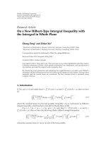
= 7MHz.
where G
T
and G
R
are the antenna gains of the UWB
transmitter and the WiMAX receiver, respectively, and L
p
is
the path loss with value L
p
= (4πf
u
d/c)
2
.Theparameters
c and d are the speed of light and the distance between the
UWB interferer and the WiMAX receiver.
Finally, the minimum distance value between v ictim
service and the interferer can be calculated by substituting
(29)and(33) into the expression P
N
= NIR
min
P
I|max
,
yielding
d
min
=
c
4πf
u
P
U
G
T
G
R
NIR
min
P
N
. (34)
Furthermore, the distance values, that delimit the zones
in the DAA mechanism of Figure 2, can be calculated by
using (34). As an example of this application, a WiMAX
system with 64-QAM R
w
c
= 3/4 scheme, nominal bandwidth
of f
s
= 2 MHz and G
T
= G
R
= 0 dBi is considered. In this
situation, the two threshold areas of the DAA algorithm are
established by setting d
min |z
1
= 0.68 m and d
min |z
2
= 14.78 m
for NIR
min
= 2dB.
4. Numerical and Simulation Results
In this section, a comprehensive analysis of the MB-
OFDM UWB interference effects on the WiMAX receiver is
carried out by means of numer ical and simulation methods.
Initially, the analytical BER expressions for uncoded and
coded WiMAX systems are validated through simulations
in Section 4.1. Thereafter, simulated BER and EVM per-
formances, provided in Section 4.2, allow the estimation
EURASIP Journal on Wireless Communications and Networking 9
0 5 10 15 20 25 30 35
10
0
10
−1
10
−2
10
−3
10
−4
SNR (dB)
BER
QPSK R
w
c
= 1/2, SUI2, CP = 1/16, TFC5, SIR = 10 dB
QPSK R
w
c
= 1/2, SUI2, CP = 1/4, TFC5, SIR = 10 dB
64-QAM R
w
c
= 3/4, SUI2, CP = 1/16, TFC5, SIR = 25 dB
64-QAM R
w
c
= 3/4, SUI2, CP = 1/4, TFC5, SIR = 25 dB
Figure 11: Average BER versus 10 log 10(SNR) for QPSK R
w
c
= 1/2
and 64-QAM R
w
c
= 3/4 WiMAX systems in TFC5 and multipath
fading channel SUI-2.
0 5 10 20 15 25 30 35 40
10
0
10
−1
10
−2
10
−3
10
−4
10
−5
10
−6
SIR (dB)
BER
QPSK R
w
c
= 1/2, AWGN, TFC5, SNR = 6dB
QPSK R
w
c
= 1/2, AWGN, TFC1, SNR = 6dB
64-QAM R
w
c
= 3/4, AWGN, TFC5, SNR = 21.5dB
64-QAM R
w
c
= 3/4, AWGN, TFC1, SNR = 21.5dB
Figure 12: Average BER versus 10 log 10(SIR) for QPSK R
w
c
= 1/2
and 64-QAM R
w
c
= 3/4 WiMAX systems in TFC5 and TFC1 modes.
The SNR is set to SNR
R
.
of the maximum permissible interference levels. The main
numerical values for both WiMAX and MB-OFDM UWB
interferer systems employed in this study are summarized in
Tab le 1.
4.1. Validation of Analytical BER Expressions. Initially, the
analytical BER expressions for the uncoded WiMAX systems,
obtained in section Section 3.1, are validated by means of
numerical and simulation results. Firstly, the BER curves
foruncodedWiMAXsystemswithQPSKand64-QAM
modulation schemes in the situation of AWGN channel and
Table 1: WiMAX and MB-OFDM main parameters.
WiMAX
Parameters
Values
N
w
s
256
f
w
3.5 GHz
W
w
{1.75, 7, 17.5}MHz
T
w
256/W
w
T
w
cp
{0, 1/4, 1/16}T
w
T
w
s
{1, 5/4, 17/16}T
w
R
cc
= k
cc
/n
cc
2/3 (QPSK 1/2)
5/6 (64-QAM 3/4)
β
d
[3, 70, 285, 1276, 6160, 27128, 117019]
(QPSK 1/2)
[92, 528, 8694, 79453, 792114, 7375573]
(64-QAM 3/4)
d
f
6 (QPSK 1/2)
4 (64-QAM 3/4)
RS (n
rs
, k
rs
, T)
RS(32,24,4) (QPSK 1/2)
RS(120,108,6) (64-QAM 3/4)
MB-OFDM UWB
Parameters
Values
N
u
s
128
f
u
2904 + i528 MHz; i = 1(TFC5),i ={1, 2, 3}
(TFC1)
W
u
528 MHz
T
u
242.42 ns
T
u
cp
70.07 ns
T
u
s
312.5ns
R
u
b
200 Mbps
nonfaded MB-OFDM UWB interference signals are plotted
in Figure 6. For comparison purposes, the simulated and
numerical BER waterfall curves of these WiMAX systems
without presence of interference are also represented in
Figure 6. In this scenario, the CF of the nonfaded inter-
ference, calculated in (19), is replaced by the Gaussian CF
expression ψ
i
k
(s) ≈ exp(−s
2
σ
2
γ
/2), since μ
1
= μ
2
= 1. The
results illustrate that simulated BER curves are identical to
the analy tical results.
Secondly, the BER curves of a WiMAX system with
QPSK modulation, in the presence of Rayleigh-amplitude
faded interference with TFC5 hopping pattern, are depicted
in Figure 7 for different SIR levels. The BER curves with
faded interference are compared to those with nonfaded
interference. The numerical results show that when the SIR
is low (SIR
= 5 dB and SIR = 10 dB), the faded interference
improves the BER performance, with respect to the nonfaded
interference case, since the pdf of the faded interference has
larger values at the origin than the Gaussian pdf, as shown
in Figure 4. However, the tails of the faded interference pdf
display a larger amount of energy than the Gaussian pdf,
causing a degradation of the BER performance when the SIR
levels are high (SIR
= 15 dB). In this scenario, the numerical
BER curves also perfectly match the simulation results.
10 EURASIP Journal on Wireless Communications and Networking
10 15 20 25 30 35 40
0
10
20
30
40
50
60
SIR (dB)
EVM (%)
QPSK R
w
c
= 1/2, AWGN, TFC5, SNR = 6dB
QPSK R
w
c
= 1/2, AWGN, TFC1, SNR = 6dB
64-QAM R
w
c
= 3/4, AWGN, TFC5, SNR = 21.5dB
64-QAM R
w
c
= 3/4, AWGN, TFC1, SNR = 21.5dB
1% SNR sensitivity threshold, QPSK R
w
c
= 1/2
1% SNR sensitivity threshold, 64-QAM R
w
c
= 3/4
Figure 13: Percentage EVM versus 10 log 10(SIR) for QPSK R
w
c
=
1/2 and 64-QAM R
w
c
= 3/4 WiMAX systems in TFC5 and TFC1
modes. The SNR is set to SNR
R
and two threshold values are plotted
following the 1% criterion.
Furthermore, the numerical and simulated BER expres-
sions of the QPSK modulated WiMAX link, impaired
by faded interference and Rayleigh fading, are plotted in
Figure 8 for different values of the SIR. The simulated
BER curves validate the theoretical analysis presented in
Section 3.1.
Finally, the BER perfor mance of the analytical upper
bound coded WiMAX systems, using the burst profiles QPSK
R
w
c
= 1/2 and 64-QAM R
w
c
= 3/4, are validated by means
of simulation results, as shown in Figure 9. The simulation
and numerical results are obtained by considering an AWGN
channel and an interference-free scenario. The improvement
in BER performance, resulting from the addition of the
concatenated RS-CC coding to both systems with respect to
the uncoded systems, is clearly manifested for high values of
SNR. The required values of SNR, that guarantee a BER value
of 10
−6
, are obtained from Figure 9 as SNR
R
= 6dB and
SNR
R
= 21.5 dB for QPSK R
w
c
= 1/2 and 64-QAM R
w
c
= 3/4,
respectively. These values will be employed for estimating the
interference levels in further analysis. It is noticeable that the
analytical upper bound BER performances are in agreement
with the simulated waterfall BER curves for large SNR values.
4.2. Simulation Results: Evaluation of Interference Effects. The
average BER performances, as a function of the received SIR
of the two modulation-coding WiMAX systems, are plotted
in Figure 10 for both frequency-hopped (TFC1) and fixed
(TFC5) types of interference. In order to correctly assess
the effect of the interference signal on the victim service, as
the only source of distortion, the AWGN noise contribution
is considered negligible in this simulation scenario (SNR
→
∞
).
Initially, it is noticeable that the BER of the TFC5
interference systems degrades by approximately 4.5dB with
respect to the TFC1 systems. This is due to the fact that
only one third of the UWB interference s ymbols with TFC1
frequency hopping pattern cause interference to the WiMAX
link. The Gaussian behavior of the interference can also
be observed in this analysis. The BER waterfall curves of
the TFC5 interference systems are almost identical to the
noninterference coded BER curves, represented in Figure 9,
but shifted approximately 1.5 dB. This is due to the larger
value of the interference variance.
Two WiMAX systems with transmission bandwidth
values W
w
= 7 MHz and W
w
= 1.75 MHz are used in
this initial analysis. The BER performances of these systems,
plotted in Figure 10 for the case of TFC5, are shown to
be practically identical, leading to the conclusion that the
MB-OFDM UWB interference effects on an IEEE 802.16-
2004 WiMAX system in an AWGN channel is independent
of its subcarrier spacing. It was shown in [15] that the BER
performance of a WiMAX system degrades as the subcarrier
separation of the UWB interferer decreases. However, in the
inverse situation, in which the subcarrier separation of the
interference is fixed to Δ f
u
= 4.125 MHz, the interference
distortion on WiMAX systems with W
w
= 7 MHz (Δ f
w
=
27.34 KHz) and W
w
= 1.75 MHz ( Δ f
w
= 6.83 KHz) behaves
the same since only very few UWB subcarriers contribute
to the interference component within the narrow WiMAX
bandwidth.
In the following analysis, a more realistic simulation
environment is applied by considering a multipath fading
channel. The radio channel is based on the Stanford
University Interim (SUI) channels for fixed broadband
wireless access systems [27].TheSUImodelisasetofsix
channels that characterize the impulse response for three
different types of terrains, considering the mobility of the
user by means of the Doppler spread parameter. Each SUI
multipath channel is obtained by defining three taps with
the corresponding power, delay spread, and K-factor. In this
set of simulations, SUI-2 channel (which accounts for low
delay spread and low Doppler spread values) is considered for
evaluating the BER performance of the WiMAX systems with
W
w
= 17.5 MHz impaired by TFC5 interference signals, as
illustrated in Figure 11. In this simulation study, SIR
= 10 dB
and SIR
= 25 dB are set for QPSK R
w
c
= 1/2 and 64-QAM
R
w
c
= 3/4, respectively. The resulting BER simulations show
the degradation of performance when using a short cyclic
prefix of CP
= 1/16 with respect to a long prefix of CP = 1/4.
This performance degra dation is caused by the fact that the
excess delay D
w
= 1 μs of the three-path SUI-2 channel is
larger than T
w
cp
= 0.9 μs when CP = 1/16. In contrast, the
excess delay is less than T
w
cp
= 3.7 μs when CP = 1/4is
employed. It can also be observed that the BER curves tend
to a particular floor value for high SNR, which is determined
by the fixed SIR levels.
Finally, the estimation of the maximum allowable inter-
ference levels and the SIR levels that allow the interference
signal to be considered negligible are obtained by means
of simulations in the following analysis. The BER perfor-
mances, as a function of the received SIR for the two
EURASIP Journal on Wireless Communications and Networking 11
burst profiles with fixed received SNR values, are plotted
in Figure 12. In this study, the WiMAX bandwidth is set
to W
w
= 7 MHz and MB-OFDM UWB interferers employ
both TFC1 and TFC5 hopping patterns. The received SNR
values are chosen as those that guarantee a BER
= 10
−6
in AWGN channel conditions (SNR
R
), which are obtained
in Figure 9 and correspond to 6 dB and 21.5 dB for QPSK
R
= 1/2 and 64-QAM R = 3/4, respectively. As previously
mentioned in the analytical approach (Section 3.3), the
maximum permissible UWB interference level is set to the
noise floor, yielding SIR
min
= SNR
R
+ 3 dB in (32). In
this situation, the BER perform ance degrades considerably
with respect to the case of noninterference, especially when
TFC5 is employed, obtaining BER values of approximately
1
· 10
−3
and 5 · 10
−5
for QPSK R
w
c
= 1/2 and 64-
QAM R
w
c
= 3/4, respectively . Therefore, a more precise
approach must be adopted for neglecting the interference.
It is stipulated in [28] that an interference signal can be
neglected when its effects on the measured metrics are
≤ 1%.
The SIR values that are compliant with the 1% criterion
can be obtained in a more accurate manner by analyzing
the EVM performance instead of the BER. The EVM is
a baseband system-level metr ic that allows the quality of
the system to be evaluated by calculating the error in the
constellation diagram. Also, the computation of the EVM
metric is faster and less complex to obtain in both simulation
and experimental studies. The EVM performance of the two
coded systems are represented in Figure 13 under the same
scenario as previously indicated. The percentage of EVM of
a QPSK R
w
c
= 1/2 system, in AWGN without interference
when operating at its minimum sensitiv ity (SNR
R
= 6dB),is
calculated as 39.15%. Similarly, a percentage EVM of 6.55%
is required for 64-QAM R
w
c
= 3/4withSNR
R
= 21.5dB.
By applying a 1% factor to these values, the two thresholds
are obtained, as shown in Figure 13. Under these conditions
and using the 1% criterion, it can be concluded that
the SIR values for noninterference coexistence operability
(SIR
IF
)are19dBand23.5 dB for QPSK R
w
c
= 1/2with
TFC1 and TFC5, respectively. For 64-QAM R
w
c
= 3/4, the
SIR
IF
values are 32 dB and 36.5dB for TFC1 and TFC5,
respectively.
5. Experimental Results
The objective of the measurement analysis is to estimate
the interference margin levels, SIR
min
and SIR
IF
,inorder
to validate the results previously obtained in the simulation
study. Initially, the laboratory test bed, implemented for
the measurement campaign, is described in Section 5.1.
Subsequently, measurement results given by EVM and SEP
metrics are provided in Section 5.2 for different types of
interference scenarios.
5.1. Laboratory Test Bed Description. The laboratory test
bed for coexistence study between WiMAX and MB-OFDM
UWB in the conducted modality is depicted in Figure 14.The
instruments employed are listed as follows.
(i) WiMAX baseband vector signal generator (Rohde
& Schwarz SMBV100A). Upconverter: Agilent PSG
E8267D.
(ii) WiMAX Receiver: Tektronix Real-Time Spectrum
Analyzer RSA3408B.
(iii) WiMAX Demodulator: WiMAX IQSignal software
application running on a stand-alone pc.
(iv) Two UWB MB-OFDM Sources: (1) Tektronix
AWG7000B UWB Signal Generator. (2) Wisair
DV9110 WiMedia evaluation system operating in the
test mode connected to a variable attenuator (0–
69 dB).
(v) Signal combiner.
This test bed has been designed to monitor the errors
in the WiMAX channel for any arbitrary values of SNR and
SIR. The test bed has the advantage of employing a realtime
spectrum analyzer as a programmable WiMAX receiver.
Therefore, full control of the receiver parameters, such as
center frequency, bandw idth, sampling frequency, and exter-
nal triggering, is achieved. Also, it allows the use of a WiMAX
demodulator software that provides a quantitative estimation
of the interference impact on the WiMAX receiver. However,
the noise figure of the spectrum analyzer is poorer than the
state of the art WiMAX receiver and this difference needs to
be taken into account in the measurements. An estimated
noise floor of the spectrum analyzer of
−84 dBm/MHz is
obtained, which is approximately 20 dB poorer than a typical
state of the art WiMAX receiver. Furthermore, the analog-
to-digital conversion in the spectrum analyzer is made with
16-bits and, therefore, the receiver has a dynamic above
90 dB. This c an be significantly increased using the auto
range functionality that s ets an adaptive level of the reference
signal.
5.2. Measurement Results. Initially, the performance of the
two burst profile WiMAX systems, QPSK R
w
c
= 1/2 and 64-
QAM R
w
c
= 3/4, is evaluated in an AWGN channel without
the presence of interference in order to obtain a performance
benchmark for the measurement setup. The EVM perfor-
mances, as a function of the received SNR, are illustrated
in Figure 15(a) for WiMAX systems with W
w
= 7 MHz.
Each plotted curve corresponds to an extensive series of 250
measurements, since 25 different power levels ranging from
−80 to −25 dBm have been used, and each measured value is
obtained from averaging 10 measurement realizations. This
procedure is applied for all the measurements performed in
this work. The measurement results show that the minimum
SNR values, that guarantee a WiMAX channel free of errors
(i.e., sensitivity of the receiver), are approximately 6 dB and
22 dB for QPSK R
w
c
= 1/2 and 64-QAM R
w
c
= 3/4,
respectively. These SNR
R
values are in agreement with those
obtained in the simulation analysis in Section 4.2. Note that
symbol er rors are represented by black-filled markers in the
graphical representations.
An interference scenario with a dominant MB-OFDM
UWB interference signal, whose power level is significantly
larger than the thermal noise in the WiMAX channel, is
12 EURASIP Journal on Wireless Communications and Networking
UWB MB-OFDM
WiMax
baseband generator
SMBV100A
Combiner
Up-converter
E8267D
WiMax
receiver
RSA3408A
UWB MB-OFDM
WiMax
3.5 GHz
LAN
LAN
WiMax
demodulator
control PC
(1) AWG7122B
(2) Wisair sample device
Figure 14: Laborator y setup for conducted tests.
5 101520253035404550
0
5
10
15
20
25
30
35
40
SNR (dB)
EVM (%)
QPSK R
w
c
= 1/2, AWGN, W
w
= 7MHz
64-QAM R
w
c
= 3/4, AWGN, W
w
= 7MHz
(a) %EVM versus 10 log 10 (SNR)
5 101520253035404550
0
5
10
15
20
25
30
35
SIR (dB)
EVM (%)
QPSK R
w
c
= 1/2, W
w
= 7 MHz, TFC5
64-QAM R
w
c
= 3/4, W
w
= 7 MHz, TFC5
(b) %EVM versus 10 log 10 (SNR)
Figure 15: Measured percentage EVM performances for QPSK R
w
c
= 1/2 and 64-QAM R
w
c
= 3/4. (a) Interference-free scenario. (b) TFC5
Interference with NIR
= 11 dB.
considered in the following analysis. The MB-OFDM UWB
interference signals, with R
b
= 200 Mbps and power spectral
density (PSD) of
−73 dBm/Mhz, are generated from the
AWG7112B signal generator for TFC5 frequency-hopping
pattern. This PSD value is 11 dB larger than the noise
floor. The measurement campaign is carried out in the
worst possible interfering scenario, which corresponds to a
duty cycle of the interference signal of 100%. The average
received EVM performances for the two burst profiles under
these interference conditions are shown in Figure 15(b).The
results illustrate that the WiMAX receiver with concatenated
RS-CC coding is not capable of successfully demodulating
the symbols when the SIR level is very low for TFC5
interference signalling. In particular, there are symbol errors
when SIR
≤ 8 dB and SIR ≤ 24 dB for QPSK R = 1/2
and 64-QAM R
= 3/4, respectively. For larger values of the
SIR, the measured EVM values are the same for both burst
profiles and slightly larger than those without interference
and AWGN noise.
Finally, a set of conducted measurements employing the
WiMedia sample device (i.e., a Wisair DV9110 WiMedia
evaluating system operating in the test mode) with TFC5 and
a WiMAX link, with 64-QAM R
w
c
= 3/4 scheme, are carried
out in the following analysis. In order to conveniently adjust
the output power of the UWB sample device, a variable
attenuator is employed. The level of the interfering signal is
selected to obtain interference-to-noise (INR) levels between
2dBand
−11 dB. The objective here is to estimate the value
of SIR
IF
for the situation of neglected interference. In the test
mode, this sample device operates with a fixed duty cycle of
50%, a frame duration of 600 μs and a constant data rate of
200 Mbps. The measurement results illustrate that the effects
of the interference signal become negligible w hen NIR
≥
10 dB, as shown in Figure 16(a) when EVM is the measured
metric and in Figure 16(b) for the symbol error probability
(SEP) analysis. This NIR l imit value corresponds to an EVM
of
−24 dB (i.e., 6.31 of %EVM). This value is in agreement
with the simulated threshold for 64-QAM R
w
c
= 3/4 obtained
in Section 4.2. Thus, the measurement results validate the
SIR
IF
values obtained by simulations.
6. Conclusions
New EIRP masks released by the European Commission
in its Decision 2007/131/EC regulate the radio spectrum
use for UWB equipment in the European Community.
EURASIP Journal on Wireless Communications and Networking 13
−2024681012
10
0
10
−1
10
−2
10
−3
10
−4
NIR (dB)
SEP
(a) %EVM versus 10 log 10 (NIR)
−2024681012
−24.5
−23.5
−22.5
−21.5
−24
−23
−22
−21
NIR (dB)
EVM (dB)
64-QAM R
w
c
= 3/4, AWGN, TFC5
(b) %EVM versus 10 log 10 (NIR)
Figure 16: Measured EVM and SEP performances for 64-QAM
R
w
c
= 3/4 WiMAX systems in the presence of an MB-OFDM UWB
interference in TFC5 mode.
In particular, UWB devices are required to use interference
mitigation techniques in order to coexist with licensed
BWA systems, such as WiMAX at 3.5 GHz, without causing
harmful interference. The DAA mechanism, based on the
definition of three zones of opera tion, dynamically allocates
the power of the UWB devices by sensing the presence of
WiMAX activity.
The objective of this work is to evaluate the performance
of the WiMAX victim receiver under the presence of a single
MB-OFDM UWB interferer with DAA capabilities. In the
context of interference, a WiMAX receiver, operating in
DL at its minimum sensitivity level impaired by an MB-
OFDM UWB active interferer located in Zone 1 of the DAA
protection area, was identified as the most critical scenario. A
comprehensive analysis of these interference effects has been
provided in this paper by means of theoretical, simulation
and measurement approaches.
Novel analytical expressions of the BER for uncoded and
coded WiMAX systems, impaired by a single MB-OFDM
UWB interference signal, were provided in this paper for
both AWGN and Rayleigh fading channel environments. The
BER expressions were obtained by applying the inversion
theorem, which expresses the BER as a function of the
characteristic function of the decision variable. In this
approach, the complexity associated with calculating the
exact BER is reduced by first computing the characteristic
function of the received interference contribution. Further-
more, the maximum allowable interference levels SIR
min
were analytically obtained.
An extensive simulation analysis has been provided
in this paper. Initially, the analytical BER expressions for
uncoded QPSK and 64-QAM WiMAX systems, in the
presence of a MB-OFDM UWB interference signals, were
validated through simulations for different scenarios. Fur-
thermore, the upper bound analytical BER expressions for
coded QPSK R
w
c
= 1/2 and 64-QAM R
w
c
= 3/4 were also
validated through simulations. Subsequently, the simulation
results showed that the effect of the nonhopping UWB
interference on the WiMAX link is 4.5 dB larger than the
hopping one. This is due to the fact that the frequency-
hopped interference is only active one third of the time. The
Gaussian behavior of the MB-OFDM UWB interference was
also illustrated in the simulation analysis. Furthermore, it
was shown that the MB-OFDM UWB interference effects on
an IEEE 802.16-2004 WiMAX system in an AWGN channel
is independent of its subcarrier spacing.
The simulation results also showed the effects of the
intersymbol interference caused by selecting a short cyclic
prefix length of the WiMAX signal in a multipath channel
environment.
This simulation study allowed the BER values for SIR
=
SIR
min
to be gr aphically measured. In this situation, the
results showed that the BER degrades considerably with
respect to the case of noninterference, especially when TFC5
is employed. More restrictive SIR levels are required in
order to neglect the UWB interference effects. The 1%
criterion was employed on the EVM performance to estimate
the SIR
IF
levels. It has been demonstrated that the SIR
values for noninterference coexistence operability are 19 dB
and 23.5 dB for QPSK R
w
c
= 1/2 with TFC1 and TFC5,
respectively. For 64-QAM R
w
c
= 3/4, the SIR
IF
values are
32.5dBand36.5 dB for TFC1 and TFC5, respectively.
Measurements in a conducted modality have been car-
ried out to analyze the effects of the UWB interference
on the WiMAX link for two defined situations. Firstly, the
UWB interference level is larger than the noise floor allowing
SIR
min
levels, with no symbol errors in the demodulation
process, to be set. Secondly, the UWB interference is of the
order of the noise floor and the WiMAX receiver operates at
its minimum sensitivity level. In this s ituation, it is concluded
that the effects of the interference signal become negligible
when the NIR is larger than 10 dB.
References
[1] D. Porcino and W. Hirt, “Ultra-wideband radio technology:
potential and challenges ahead,” IEEE Communications Maga-
zine, vol. 41, no. 7, pp. 66–74, 2003.
[2] IEEE Std. 802.16-2004, “IEEE Standard for Local and
Metropolitan Area Networks, Part 16: Air Interface for Fixed
14 EURASIP Journal on Wireless Communications and Networking
and Mobile Broadband Wireless Access Systems,” October
2004.
[3] IEEE Std. 802.16e-2005, “IEEE Standard for Local and
Metropolitan Area Networks, Part 16: Air Interface for Fixed
and Mobile Broadband Wireless Access Systems, Amendment
for Physical and Medium Access Layers for Combined Fixed
and Mobile Operation in Licensed Bands,” February 2006.
[4] Federal Communications Commission (FCC), “Revision of
Part 15 of the Commissions Rules Regarding Ultra-Wideband
Transmission Systems,” First Report and Order ET Docket 98-
153, FCC 02-48, April 2002.
[5] European Commission Decision 2007/131/EC, “Allowing the
Use of the Radio Spectrum for Equipment Using Ultra-
Wideband Technology in a Harmonised Manner in the
Community,” June 2007.
[6] ECC Repot 120, “Technical Requirements for UWB DAA
(Detect and Avoid) Devices to Ensure the Protection of
Radiolocation in the Bands 3.1–3.4 GHz and 8.5–9 GHz and
BWA Terminals in the Band 3.4–4.2 GHz,” February 2007.
[7] A. Batra, J. Balakrishnan, G. R. Aiello, J. R. Foerster, and A.
Dabak, “Design of a multiband OFDM system for realistic
UWB channel environments,” IEEE Transactions on Microwave
Theory and Techniques, vol. 52, no. 9 I, pp. 2123–2138, 2004.
[8] S. M. Mishra, S. ten Brink, R. Mahadevappa, and R. W.
Brodersen, “Cognitive technology for ultra-wideband/WiMax
coexistence,” in Proceedings of the 2nd IEEE International
Symposium on New Frontiers in Dynamic Spectrum Access
Networks, pp. 179–186, April 2007.
[9]A.Rahim,S.Zeisberg,andA.Finger,“Coexistencestudy
between UWB and WiMax at 3.5 GHz band,” in Proceedings
of IEEE International Conference on Ultra-Wideband (ICUWB
’07), pp. 915–920, September 2007.
[10] F. Facchini, R. Giuliano, and F. Mazzenga, “Ultra-wideband
detect and avoid procedure for WiMAX victims,” IET Com-
munications, vol. 3, no. 2, pp. 268–278, 2009.
[11] A. Durantini, R. Giuliano, F. Mazzenga, and F. Vatalaro,
“Performance evaluation of detect and avoid procedures
for improving UWB coexistence with UMTS and WiMAX
systems,” in Proceedings of IEEE International Conference on
Ultra-Wideband (ICUWB ’06), pp. 501–506, September 2006.
[12] R. Kogane, C. Fukao, J. Hioki et al., “A study on the detection
scheme of WiMAX signal for DAA operation in MB-OFDM,”
in Proceedings of IEEE International Conference on Ultra-
Wideband (ICUWB ’07), pp. 834–839, September 2007.
[13] J. Perez, M. Beltr
´
an, M. Morant, R. Llorente, and L. Cavallin,
“Protection margins for joint operation of WiMAX 802.16e
and WiMedia-defined UWB radio in personal area networks,”
in Proceedings of IEEE International Conference on Ultra-
Wideband (ICUWB ’09), pp. 723–727, Vancouver, Canada,
September 2009.
[14] K W. Kim, J. Park, J. Cho et al., “Interference analysis
and sensing threshold of detect and avoid (DAA) for UWB
coexistence with WiMax,” in Proceedings of the 66th IEEE
Vehicular Technology Conference (VTC ’07), pp. 1731–1735,
October 2007.
[15] A. Nasri, R. Schober, and L. Lampe, “Performance evaluation
of BICM-OFDM systems impaired by UWB interference,” in
Proceedings of IEEE International Conference on Communica-
tions (ICC ’08), pp. 3616–3621, May 2008.
[16] C. Snow, L. Lampe, and R. Schober, “Error rate analysis for
coded multicarrier systems over quasi-static fading channels,”
IEEE Transactions on Communications, vol. 55, no. 9, pp. 1736–
1746, 2007.
[17] C. Snow, L. Lampe, and R. Schober, “Analysis of the impact of
WiMAX-OFDM interference on multiband OFDM,” in Pro-
ceedings of IEEE International Conference on Ultra-Wideband
(ICUWB ’07), pp. 761–766, September 2007.
[18] European Computer Manufacters Association (ECMA),
“Standard ECMA-368: High Rate Ultra Wideband PHY and
MAC Standard,” December 2005.
[19] O. Edfors, M. Sandell, J. van de Beek, D. Landstrom,
and F. Sjoberg, “An introduction to orthogonal frequency-
division multiplexing,” Research Report, 1996,
.luth.se/csee/sp/publications/.
[20] J. Gil-Pelaez, “Note on the inversion theorem,” Biometrika, vol.
38, no. 3/4, pp. 481–482, 1951.
[21] J. G. Proakis, Digital Communications, McGraw-Hill, New
York, NY, USA, 5th edition, 2008.
[22] D. Yoon, K. Cho, and J. Lee, “Bit error probability of M-ary
quadrature amplitude modulation,” in Proceedings of the 52nd
Vehicular Technology Conference (VTC ’00), vol. 5, pp. 2422–
2427, September 2000.
[23] D. Haccoun and G. Begin, “High-rate punctured convo-
lutional codes for Viterbi and sequential decoding,” IEEE
Transactions on Communications, vol. 37, no. 11, pp. 1113–
1125, 1989.
[24] P. Frenger, P. Orten, and T. Ottosson, “Convolutional codes
with optimum distance spectrum,” IEEE Communications
Letters, vol. 3, no. 11, pp. 317–319, 1999.
[25] R. D. Wessel, “Convolutional codes,” in Wiley Encyclopedia of
Telecommunications, J. G. Proakis, Ed., vol. 1, pp. 598–606,
John Wiley & Sons, Hoboken, NJ, USA, 2003.
[26] M O. Wessman, A. Svensson, and E. Agrell, “Frequency
diversity performance of coded multiband-OFDM systems on
IEEE UWB channels,” in Proceedings of the 60th IEEE Vehicular
Technology Conference (VTC ’04), pp. 1197–1201, September
2004.
[27] V. Erceg, et al., “Channel Models for Fixed Wireless Applica-
tions,” IEEE 802.16.3c-01/29rl, February 2001.
[28] ECC Report 64, “ The Protection Requirements of Radiocom-
munications Systems Below 10.6 GHz from Generic UWB
Applications,” February 2005.