Báo cáo hóa học: " Research Article SET: Session Layer-Assisted Efficient TCP Management Architecture for 6LoWPAN with Multiple Gateways" ppt
Bạn đang xem bản rút gọn của tài liệu. Xem và tải ngay bản đầy đủ của tài liệu tại đây (1.18 MB, 20 trang )
Hindawi Publishing Corporation
EURASIP Journal on Wireless Communications and Networking
Volume 2010, Article ID 936457, 20 pages
doi:10.1155/2010/936457
Research Ar ticle
SET: Session Layer-Assisted Efficient TCP Management
Architecture for 6LoWPAN with Multiple Gateways
Saima Zafar,
1
Ali Hammad Akbar,
2
Sana Jabbar,
3
and Noor M. Sheikh
1
1
Department of Electrical Engineering, University of Engineering and Technology, UET, Lahore 54890, Pakistan
2
Department of Computer Science, University of Engineering and Technology, UET, Lahore 54890, Pakistan
3
Al-Khawarzmi Institute of Computer Science, University of Engineering andTechnology, UET, Lahore 54890, Pakistan
Correspondence should be addressed to Saima Zafar, saima
Received 12 March 2010; Revised 10 August 2010; Accepted 15 September 2010
Academic Editor: A. C. Boucouvalas
Copyright © 2010 Saima Zafar et al. This is an open access article distributed under the Creative Commons Attribution License,
which permits unrestricted use, distribution, and reproduction in any medium, provided the original work is properly cited.
6LoWPAN (IPv6 based Low-Power Personal Area Network) is a protocol specification that facilitates communication of IPv6
packets on top of IEEE 802.15.4 so that Internet and wireless sensor networks can be inter-connected. This interconnection is
especially required in commercial and enterprise applications of sensor networks where reliable and timely data transfers such as
multiple code updates are needed from Internet nodes to sensor nodes. For this type of inbound traffic which is mostly bulk, TCP
as transport layer protocol is essential, resulting in end-to-end TCP session through a default gateway. In this scenario, a single
gateway tends to become the bottleneck because of non-uniform connectivity to all the sensor nodes besides being vulnerable to
buffer overflow. We propose SET; a management architecture for multiple split-TCP sessions across a number of serving gateways.
SET implements striping and multiple TCP session management through a shim at session layer. Through analytical modeling and
ns2 simulations, we show that our proposed architecture optimizes communication for ingress bulk data transfer while providing
associated load balancing services. We conclude that multiple split-TCP sessions managed in parallel across a number of gateways
result in reduced latency for bulk data transfer and provide robustness against gateway failures.
1. Introduction
A Wireless Sensor Network (WSN) is formed by end
devices (sensor nodes) equipped with sensors, microcon-
trollers, radio transceivers, and battery sources. Some of
the applications of WSN are habitat monitoring, battlefield
monitoring, shooter localization, process monitoring and
control, environmental monitoring, healthcare applications,
home automation, traffic control, and so forth. The size,
cost, and capabilities of sensor nodes vary depending upon
application requirements, size of sensor network, business
demands, and application complexity. In the past, the scope
of WSNs was limited to research projects and undemanding
applications. Sensor nodes with limited capabilities were
sufficient for such applications. Recently, WSNs have been
foreseen to evolve towards commercial applications and
sensor nodes, with superior capabilities being developed
in order to meet such application demands. Some of the
research challenges for commercial WSNs are support for
multiple applications, several service providers sharing a
single-sensor network, WSN and the Internet connectivity,
and reliable, timely, and multiple code updates thereof.
The IEEE 802.15.4 working group maintains the stan-
dard which specifies physical and MAC layers for Wireless
Personal Area Networks (WPANs) such as WSN. For com-
mercial and public usage of WPANs, efforts are underway
to connect them to the Internet, especially through IPv6.
This owes to the fact that the Internet, although both
IPv4 and IPv6 are coexistent at present, is directed towards
complete transition to IPv6 due to address range limitations
in IPv4. 6LoWPAN aims at realizing such connectivity and is
especially targeting IEEE 802.15.4 as the baseline technology
for WSNs. By supporting IPv6, sensor nodes are able to
communicate with any IPv6-enabled host over the Internet,
benefit from standardized and already established services,
and network management tools, and achieve end-to-end
2 EURASIP Journal on Wireless Communications and Networking
reliable communication over the Internet through existing
transport protocols.
Data transfer from WSN nodes to the Internet node
is irregular and event driven, but data transferred from
the Internet node to WSN nodes depends upon the nature
of application. In simple applications, this data can com-
prise simple code updates that are nontime critical and
mostly one-time activity. But in critical mission-oriented
military applications this data is both time critical and
loss intolerant. Similarly, in many enterprise or commercial
applications of WSN [1–5], it is reasonable to share a large
number of deployed sensor nodes to accomplish multiple
tasks required by different application service providers. As
elaborated in [2], wireless sensor networks supporting mul-
tiple applications reduce the deployment and management
costs, which results in higher network efficiency. For such
shared networks, multiple code updates are needed from
the Internet to WSN sensor nodes. Active redeployment
of applications is also needed with changes in conditions,
thus requiring code updates to sensor nodes. Similarly,
application software upgrades by network administrators
demand reliable code dissemination to sensor nodes. The
code updates from the Internet to WSN are time critical
and loss intolerant but often suffer from packet loss due
to erroneous channel behavior and faulty network ele-
ments. Therefore, TCP implementation over 6LoWPAN is
required.
The inbound TCP sessions (from the Internet to WSN)
are mostly bulk-data transmission from the correspondent
node (CN) in the Internet to sensor nodes (SN) in WSN. The
communication model for interconnectivity of the Internet
with WSN is through a gateway (GW). The gateway is
responsible to perform tasks like fragmentation and reassem-
bly of IP packets to address MTU mismatch. In this paper,
first of all, we identify TCP-session overflow disposition
of a single gateway, due to fragmentation implemented
for the Internet and WSN interconnectivity. We believe
that a single gateway supporting a large number of TCP
sessions is vulnerable to buffer overflow that results in packet
losses requiring end-to-end (CN-SN) retransmissions. The
gateway, though a layer-five device, remains unaware of
overflow situation which could otherwise be effectively
prevented.
We propose SET which is a session layer-based architec-
ture that staggers a single CN-SN session into multiple split
(CN-GW and GW-SN) sessions, across a number of available
6LoWPAN gateways (or for an equivalent device for IPv4)
and stripes data across these sessions. SET is implemented
only through ashim layer above the transport layer at the cor-
respondent node, gateway, and sensor node, not burdening
either of these in terms of memory and processing overhead.
Data striping is achieved through demultiplexing application
data at the sender to send it through different available
paths to a destination (or a set of destinations), where it is
reassembled to be delivered to receiver application. SET does
not interfere with TCP semantics which is there to guarantee
flow control, congestion control, and reliability. Striping
data across multiple gateways to multiple TCP sessions in
6LoWPANsetting,aswehaveproposedinSET,isthefirst
ever work of its kind. Striping has not been investigated for
multiple gateways, although it is indeed used to improve
throughput in multihomed end systems. Multihomed end
systems are those that have multiple interfaces to connect
to various available networks such as cellular, wireless local
loops, and Wi-Fi networks.
The remainder of the paper is organized as follows. In
Section 2, we discuss the related work. Section 3 highlights
the motivation for this research, and Section 4 presents the
proposed mechanism in detail. In Section 5,wemathemat-
ically analyze TCP performance when SET is implemented.
Section 6 presents experimental results based on ns2 simu-
lations. Finally, Section 7 summarizes results and concludes
the paper.
2. Related Work
One of the challenges in 6LoWPAN for enterprise use
of sensor network is efficient and timely multiple code
update from the Internet node to sensor nodes. Some of
the recent work in this area is [1–5]. In [2], Yu et al.
state that it is necessary to support multiple applications
simultaneously on the wireless sensor network in order to
reduce the related costs of deployment and administration.
This results in improvement in usability and efficiency of
the network. They describe a system called Melete that
supports parallel applications for consistency, efficiency, elas-
ticity, programmability, and scalability. Dynamic grouping
is used for the need-based deployment of applications on
the basis of existing status of the sensor nodes. A code
dissemination mechanism is also presented that provides
reliable and efficient code distribution among sensor nodes.
In [3], Rittle et al. present Muse, a middleware for using
sensors efficiently. Their solution targets the scenario that
requires multiple code update in wireless sensor networks
that are multiapplication and multidomain. The authors
discuss scenarios where wireless sensor networks are evolv-
ing multiuser long-life networks. Multiple users of WSN
can perform code updates in parallel as well as sequen-
tially.
In the remaining part of this section, we discuss
important work related to our proposed solution, which
is categorized into (1) split-TCP approaches for improving
TCP performance in heterogeneous networks, (2)mul-
tiple gateway architecture in 6LoWPAN for interconnec-
tivity with other networks, and (3) a comparison of
data-striping techniques at various layers in multihomed
devices.
TCP is known to perform poorly in diverse environ-
ments connecting wired-cum-wireless networks. It has been
observed that in diverse networks, splitting TCP connection
into two parts, wired and wireless, improves throughput and
fairness. A comparison of mechanisms for improving TCP
performance over wireless links can be found in [6]. I-TCP,
split TCP, and semisplit TCP [7–10] propose some variations
of this approach and prove that splitting TCP across proxy
results in TCP performance gain. However, performance gain
is limited by congestion at the proxy and asymmetry between
EURASIP Journal on Wireless Communications and Networking 3
links. In such a scenario, proxy can become the bottleneck,
and a large number of connections supported across proxy
can result in buffer overflow at proxy as stated in [11, 12].
Efforts have also been made in order to make TCP feasible for
the resource constrained multihop WSNs. Distributed TCP
caching has been proposed by Dunkels et al. in [13, 14]that
results in local TCP-segment retransmissions in WSN in case
of packet loss.
The usage of multiple gateway architecture in 6LoWPAN
has been proposed in [15–17] in order to achieve load-
balancing, longer network lifetime, and a higher degree
of off-field communication reliability as well as multiple
gateways-assisted routing. Announcement of gateways is
proposed for advertising the presence of multiple gateways
to the sensor node a node upon receiving more than one
advertisement chooses only a single gateway for commu-
nication that is at the closest hop distance. Lofti et al. in
[16] developed and analyzed models to determine optimal
number of gateways and their location in the sensor field.
They suggest that a larger number of gateway nodes imply
a reduction in load per sensor node and hence longer life
of sensor nodes. Having a larger number of gateways also
allows higher overall capacity for communication between
sensor nodes and external users and provides redundancy.
In all of these schemes, one of the gateways has to be
selected at a time for off-field communication. The use
of multiple gateways in parallel by a single node for
inbound data communication in 6LoWPAN has never been
proposed.
Data striping has been proposed for bandwidth aggrega-
tion in multihomed devices. A comparison of data striping
and bandwidth aggregation schemes across parallel paths
between multihomed sender and receiver can be found
in [18–25] with support for striping at different layers
depending upon the application requirements. It has also
been observed that striping at higher layers leads to less
head-of-line blocking. On one hand, application layer
striping increases the complexity of applications. On the
other hand, network layer striping causes degradation in
TCP performance over diverse paths. It necessitates making
changes at the transport layer. After comparison of striping
at various layers, Habib et al. [18] argue that session-layer
striping notably improves connection semantics offered to
applications, without requiring extensive modifications in
application code or transport-layer implementations. They
support striping at session layer in their paper, but do
not present a protocol or framework for it. pTCP [20]
and mTCP [21] are transport layer striping protocols that
propose mechanisms to achieve bandwidth aggregation on
multihomed mobile hosts. In [20], pTCP is defined as a
wrapper that manages the operation of underlying paths
while TCP-v is a TCP-like connection on each path. Thus,
transport layer striping involves complex changes at the
transport layer which means development and deploy-
ment of new transport layer protocol for the management
of multiple streams. We assert that no prior work has
investigated the efficacy of data striping across multiple
split-TCP sessions through multiple gateways in 6LoW-
PAN.
3. Motivation
For reliable and timely code update in WSN, many new
transport layer protocols have been proposed, but TCP is
preferred for being the most important complete protocol
that guarantees reliability in addition to congestion control
and flow control. Therefore, research efforts are also directed
to make TCP efficient for WSN. Our research work is
an effort in this direction, where instead of proposing
a new transport layer protocol, we have proposed small
changes above transport layer in order to make TCP
efficient.
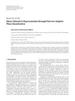
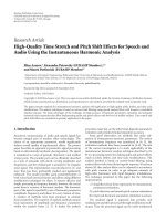
3.1. TCP Performance over 6LoWPAN. The network model
for interconnectivity of WSN and the Internet through a
default gateway is shown in Figure 1 along with protocol
stack implemented at the nodes and the gateway. The adap-
tation layer below network layer at GW and SN performs
Fragmentation and Reassembly (FnR) for MTU mismatch
between the Internet and WSN. In case of a single end-to-
end TCP session between CN and SN, the FnR of packets
at GW results in breaking the end-to-end TCP semantics. A
large number of active WSN nodes (SN) can be connected
to the Internet host (CN) through GW resulting in a large
number of active TCP connections supported by GW. In this
case, the GW forms the bottleneck of TCP connection. As
a result, incoming packets from CN get queued at GW, and
GW is susceptible to buffer overflow. Large queuing delays
at GW can degrade TCP performance with an increase in
RTT and can lead to unfairness among competing flows with
some flows experiencing excessive queuing delays and poor
performance. Thus, a single gateway, besides being a single
point of failure, is also vulnerable to buffer overflow in case
of a large number of TCP sessions. Our primary motivation
is to prevent buffer overflow at GW along with reduction in
latency of data transfer.
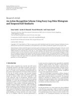
3.2. Multihoming versus Multiple Gateway. As discussed
earlier, data striping across parallel sessions through dif-
ferent paths in multihomed devices achieves bandwidth
aggregation. When end hosts are not essentially multi-
homed, but can be connected through a number of inter-
mediate gateways; data can also be striped over sessions
split across a number of gateways. Multi-homing and
multiple gateways are two different concepts. As shown
in Figure 2, multihomed devices have multiple interfaces
through which they communicate in order to achieve
high throughput. Data is striped across multiple inter-
faces that can be connected to different networks and
the goal of striping data is to utilize available band-
widths.
In 6LoWPAN, the CN in the Internet and SN in WSN are
not necessarily multihomed, but normally multiple gateways
are available for connectivity. A number of gateways can
support data transfer in parallel if data is striped across
them. Data has to be striped above transport layer in
order to achieve the objective of efficient TCP implementa-
tion.
4 EURASIP Journal on Wireless Communications and Networking
Correspondent node
(CN)
Sensor node
(SN)
Internet Gateway
Wireless sensor
network (WSN)
Application layer
Tr ansp ort l aye r
(TCP/UDP)
Network layer
(IPv6)
MAC layer
Physical layer
Application layer
Transport layer (TCP/UDP)
Network layer (IPv6)
MAC layer
Adaptation
layer
Physical layer
IEEE 802.15.4
MAC/PHY
Application layer
Tr ansp ort l aye r
(TCP/UDP)
Network layer
(IPv6)
Adaptation
layer
IEEE 802.15.4
MAC/PHY
Figure 1: 6LoWPAN single-gateway network model and protocol stack.
Multihomed
sender
Multihomed
receiver
Figure 2: Parallel sessions between two multihomed end systems.
4. Set Design
In this section, we present the design of SET, session layer-
assisted Efficient TCP management architecture. The design
elements of SET are as follows.
(i) Role of Gateway Elevated to S ession Layer. The role
of gateway is enhanced from merely being a fragmen-
tor/defragmentor in both directions to a device capable
of operating at the session layer in order to avoid buffer
overflow and to counter both packet loss and out-of-order
delivery. Consequently, TCP sessions are managed by the
upper layer, that is, the session layer in both wired and
wireless networks. The gateways play their role in imple-
menting data striping, flow control, congestion control, and
reliability.
(ii) S plit-TCP Sessions through Multiple Gateways. In SET,
split-TCP sessions (comprising of a TCP session between CN
and GW in wired network and a TCP session between GW
and SN in wireless network) are created sequentially through
“n” number of GWs. At CN, data is striped across these
sessions, and parallel data transfer takes place through “n”
split sessions.
(iii) Dynamic Buffer Assignment at the Receiver. In case of
a single end-to-end session between the sender and the
receiver, TCP sender uses the receiver’s advertised window
(receive-window) in a straightforward manner. In case of
multiple sessions, the receiver’s advertised window is used by
the sender concurrently for all sessions that traverse through
each GW. SET establishes a relationship between the link-
quality indicator (LQI) and per-session the receiver buffer
such that a larger size of receive buffer is assigned for a TCP
session with larger link bandwidth and vice versa, and the
receiver buffer is dynamically adjusted according to varying
channel conditions.
EURASIP Journal on Wireless Communications and Networking 5
Correspondent
node (CN)
Internet
GW
1
GW
2
GW
3
GW
n
Sensor node
(SN)
Wireless sensor
network (WSN)
Gateways
Figure 3: 6LoWPAN multiple gateway network model.
(iv) Flow Control. Buffer constraints of GW and SN are
unmatched, SN being a resource-constrained device; there-
fore, there is a need to reflect buffer constraints of SN to the
sender in the wired network. As flow control is implemented
independently in two TCP connections (wired and wireless)
of a single split-TCP session with mismatched MTUs, in SET,
buffer constraints of SN are reflected to CN in the wired
network in order to efficiently implement end-to-end flow
control.
(v) Congestion Control. Each split-TCP session in SET can
have different bandwidth and delay characteristics. If one
global congestion window for all sessions is used, in case of
packet loss on a single session, global congestion window
would be reduced, thus resulting in decreased throughput.
Therefore, instead of using one global congestion window,
independent congestion control for all sessions is imple-
mented.
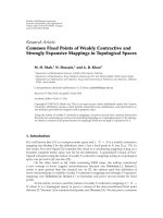
4.1. Network Model and Assumptions. The network model
for SET allows multiple TCP sessions split such that the ses-
sions traverse through distinct and nonoverlapping gateways.
This model is shown in Figure 3. In this multipath model,
the sender (CN) in the Internet can communicate with
the receiver (SN) in WSN through a number of arbitrarily
located GWs. The TCP connections from CN to GWs are on
wired links and may contain multiple intermediate routers,
while the TCP connections from GWs to SN are on wireless
links, usually passing through multiple hops. Our main
interest is the ingress trafficfromCNtoSNwhichisbulk
in nature.
We make the following assumptions:
(i) the end hosts are not essentially multihomed;
(ii) the CN, GWs and SN all support SET;
(iii) the devices support “Neighbor Discovery” protocols
(ND);
(iv) packet size in wired network is much larger than
packet size in wireless network.
4.2. SET Architecture. There are two modules in SET, namely,
Session Manager (SM) and TCP Manager (TM). The SET
architecture is shown in Figure 4. SM maintains a single
sender buffer and a single receiver buffer. When application
has data to send, the application data is copied onto
the sender buffer of SM. For one socket opened by an
application, SM opens and maintains a number of TM
sessions. SM maintains the status of all TMs. Each TM opens
a TCP socket with the transport layer. The Striping Engine
(SE) in SM divides application data into small data chunks
and passes these data chunks to TMs. The function of SE
is elaborated in Section 4.4 which discusses data striping
in detail. TM implements the functionality of each session
which SM opens. At the receiver, data is received by each TM
to which it is addressed. SM fetches data chunks from TMs
and assembles them into application data before delivering
data to the application. Acknowledgments are processed by
each TM independently. SET as a session layer protocol may
be offered through either a plug-in or an API (active X
control). CNs wishing to transmit to sensor network would
actually deploy and commission this API as a deliberate
activity. When communication with ordinary Internet nodes
is performed, CN may opt out of SET.
4.2.1. SM-TM Interface. We define the interface between
SM and each TM by six functions,
, ,
, , .SM
opens a TM session by
function and closes a TM
session by
function. TM reaches the OPENED
state after a split-TCP session (comprising of two TCP
6 EURASIP Journal on Wireless Communications and Networking
Application layer
Sessions manager
TM record SE
Send
Receive
Gateway discovery
TM
1
TM
2
TM
n
TCP
IP
···
···
···
Figure 4: SET architecture.
Sessions manager
(SM)
TM record SE
Send
Receive
Call/
release
Opened/
closed
Write Read
TCP managers
TM
1−n
Send
Receive
Figure 5: SM-TM interface.
connections) is established through a GW. Similarly, it
reaches the CLOSED state when the split-TCP session
is closed. When TM reaches OPENED and CLOSED
states, respectively, TM informs SM using
and
interfaces. Upon receiving OPENED event from
a TM, SM copies the striped data to TM sender buffer with
. TM then appends its header to this data and
passes it to the transport layer. At the receiver, SM fetches
data from TM into the receiver buffer with
. Figure 5
shows SM-TM interface.
4.2.2. Header Format. SET header has the following fields:
32-bit SET sequence number, 32-bit SET acknowledgment
number, 32-bit Intermediate destination address, 32-bit final
destination address, intermediate destination port number,
and final destination port number. The first two fields are
used to implement in-order data delivery at the receiver.
IP header TCP header SET header Payload
32 bits
SET SEQ #
SET ACK #
Intermediate destination address
(128 bits)
Final destination address
(128 bits)
Intermediate destination
port #
Final destination
port #
Figure 6: SET header format.
Intermediate destination address and intermediate destina-
tion port number are used for setting up CN to GW TCP
sessions, and final destination address and final destination
port number are used for setting up GW to SN TCP sessions.
Figure 6 shows the SET header format.
4.2.3. Connection Management. The timing diagram for code
update using SET is shown in Figure 7. CN sends a request
to SN for code update through multiple gateways. If SN
turns down the request by sending NACK to CN, SET is not
invoked. In this case, the CN establishes a TCP connection
with SN through the default gateway with gateway acting
as a router. If SN agrees, it sends ACK and also sends
gateways information to CN. In this case, SET is invoked, and
TM sessions are established sequentially through gateways
starting with the primary GW. For the first TM session,
CN opens TCP connection with GW
1
and sends TM
1
SETSYN to GW
1
. (SETSYN is the session layer SYN segment,
that is, sent to each gateway. Each gateway upon receiving
SETSYN establishes wireless part of TCP connection and
then acknowledges to CN by sending SETACK. One SET
session is said to be completed at this time.) When GW
1
receives SETSYN, it opens TCP connection with SN and
sends TM
1
SETACK to CN. Note that GW
1
must wait for
Wait-State ( ) timeout period to ensure that the “TCP ACK”
gets through to SN before it sends SETSYN to CN. At this
time, the first TM session from CN to SN through GW
1
is
complete, and data transfer begins. Data transfer follows one
complete TM session which comprises two TCP connections:
one in wired domain between CN and GW and the other in
wireless domain between GW and SN. TM sessions through
subsequent GWs are completed in a similar manner. Data
transfer from CN to SN takes place through GWs till data
transfer is complete, and sessions are released sequentially.
As SET is a session-layer protocol, therefore, connection
management in SET is management of sessions at the session
EURASIP Journal on Wireless Communications and Networking 7
CN GW
1
GW
2
GW
n
SN
TM1
session
TM2
session
TCP SYN
TCP SYNACK
ACK + SETSYN
SET ACK
Data
TCP SYN
TCP SYNACK
ACK + SETSYN
SET ACK
Data
Request for SET (UDP)
ACK + GW information
TCP SYN
TCP SYNACK
TCP ACK
Data
TCP SYN
TCP SYNACK
TCP ACK
Data
•
•
Figure 7: Timing diagram for SET connection establishment.
Closed
Open wait
Opened
(n)
Close wait
TM
1
call ( )
TM
1
opened ( )
TM
n+1
opened ( )
TM
1
release ( )
TM
n+1
closed ( )
Figure 8: Sequence diagram for connection establishment and
connection teardown.
layer. By default, conventional TCP connection management
is carried out at the transport layer, and there is no need
to discuss that. Our focus in this section is SET session
establishment and tear down, and we elaborate it with the
help of state diagram shown in Figure 8.
(i) Connection Establishment. At CN, when information
about gateways is available to SM, SM creates SET socket with
a TCB including GW
1
IP address, source port number, and
destination port number and creates first TM TCB by issuing
to it. TM appends SET header to SYN packet which
is sent to GW
1
through TCP socket which it opens with
transport layer. The TM module in GW
1
on receiving this
SYN packet creates TM TCB and returns SYNACK to CN,
which returns ACK. At this time, TM is in OPEN-WAIT state.
After TCP connection in wired, the network is complete from
CN to GW; TM in GW performs three-way handshake with
SN to establish wireless TCP connection from GW to SN. At
this time, SET ACK is sent back from GW to CN. TM at CN
reaches OPENED state, and data starts flowing from CN to
GW. SM at CN opens subsequent TM sessions one by one
through all the available gateways.
(ii) Connection Tear Down. When an application decides
to close SET, SM closes all the TM sessions by issuing
one by one. Each session closes using TCP
closing handshake. When all TMs are closed, SM enters
the CLOSED state and informs closed connection to the
application.
4.3. Role of Gateways. In 6LoWPAN, the gateway acts as a
router and implements fragmentation and reassembly for
8 EURASIP Journal on Wireless Communications and Networking
Table 1: Gateway Attributes.
GW-Id NC N-Id, N-EL HC
GW
1
01 (N
1
,E
+
)2
GW
2
11 (N
1
,E
−
)(N
2
,E
+
)(N
3
,E
+
)1
····
····
····
GW
n
10 (N
1
,E
+
)(N
2
,E
−
)2
MTU mismatch between the Internet and WSN. The gateway
being a layer-five device is underutilized in this role and can
be utilized in an efficient manner to prevent buffer overflow
and also to reduce the path of loss recovery. When a number
of gateways are available in WSN for interconnectivity with
the Internet, these gateways can be employed to make TCP
efficient. TCP sessions that pass through gateways can be
managed discretely in wired and wireless domains. By effec-
tive session management, gateways can prevent TCP session
overflow, reduce end-to-end retransmissions, and increase
throughput. The strength of SET lies in multiple gateway-
based network model that establishes the foundation on
which this protocol is built. Multiple gateways are enabled to
play an active and intelligent role besides the traditional role
of a 6LoWPAN gateway, thus assisting our protocol meet its
design goals.
4.3.1. Gateway Discovery. The candidate gateways for SET
data transfer are those which are placed in the vicinity of
SN in WSN and have SET protocol stack installed. In order
to initiate TCP sessions, CN requires information about
these gateways. As shown in timing diagram in Figure 7,this
information is sent to CN by SN when SN agrees for SET data
transfer. To discover gateways, SN implements “neighbor
discovery” protocol that is modified for 6LoWPAN [26]
and sends this information to CN. This way, CN becomes
aware of the availability, energy, one-hop neighbor, and hop-
count distance from SN of all gateways in the vicinity of SN.
CN stores and maintains a list of available gateways along
with their attributes, selects a number of gateways based
on gateway attributes, and establishes SET sessions through
selected gateways. Ta b l e 1 shows GW attributes that CN
receives from SN. The GW attributes are GW Id, Neighbor
Count (NC), Neighbor Id (N-Id), Neighbor Energy Level (N-
EL: E
+
high, E
−
low), and Hop Count from SN (HC). The
gateway at the closest hop-count distance from SN is selected
as the primary gateway.
4.3.2. Gateway Selection and Path Establishment. In case of
multihomed end systems, when multiple paths are available
for data transfer, the end systems have to determine optimal
number of paths, and then paths have to be selected based on
certain criteria. Simulations in case of multihomed devices
have shown that if the number of paths over which data is
striped exceeds a certain number, the efficiency of striping
deteriorates. Thus, in order to achieve benefits of data
striping in terms of throughput, latency, and bandwidth
aggregation, optimal number of paths have to be selected.
Another important consideration is selection of disjoint
paths that are nonoverlapping in order to ensure robustness
and to avoid paths with shared congestion. In SET, path
selection is principally a gateway selection problem because
each path is passing through a gateway. Our first goal is to
determinetheoptimalnumberofgatewaysacrosswhichdata
is to be striped and secondly to select those gateways which
are suitable to take part in communication.
Gateway selection in SET is essentially a different pro-
cedure in scope and functionality from path selection in
multihomed end systems. We elaborate it as follows.
(i) Path selection assumes homogeneous costs along
every intermediate hop in an all-wireless environ-
ment. On the contrary, in 6LoWPANs, paths are
all wired up to a 6LoWPAN gateway, after which,
paths are all wireless; consequently, the costs no
more remain homogeneous. Therefore, the hop-
count distance of a gateway from SN is a primary
consideration in gateway selection.
(ii) Selected gateways should have nonoverlapping paths.
This is realized by selecting gateways with nonover-
lapping next hops by using link-layer neighbor tables
(SMAC).
(iii) In path-selection procedures, the role of an under-
lying routing scheme is consistent. The presence of
two different routing schemes in wired and wireless
networks each, and their interplay make gateway-
selection procedure more complex; the selection of
gateways should be such that conflicts are avoided
between proactive and reactive routing protocols.
(iv) Even if a certain gateway is a good candidate to be
selected for a path, there is a possibility that the first-
hop sensor nodes from that gateway are depleted
in energy due to frequent data forwarding. Such a
case makes the gateway a bad candidate for path
establishment. CN is informed about the energy level
of first-hop neighbor of GW in addition to energy
level of GW itself. GWs with very low energy level of
neighboring nodes are not selected for SET sessions.
4.3.3. Gateway Failure. Gateway failure results in session
failure in SET. In case of gateway failure, the SET session
passing through that gateway is closed, and data transfer
through other gateways continues. Thus, sending data in
parallel through multiple gateways results in a robust
mechanism as compared to a single gateway. In order to avoid
unnecessary complexity, gateway addition or suppression is
not supported in SET during data transfer.
4.4. Dynamic Buffer Assignment. In traditional proxy servers,
buffer management is implemented in order to improve
performance and to reduce web document-transfer time.
In [27] Okomoto et al. proposed dynamic receive socket
buffer, allocation at web proxy servers. Their proposed
scheme assigns the proper size of the receiver buffer to
EURASIP Journal on Wireless Communications and Networking 9
each TCP connection which downloads the original web
document from distant web server via web proxy server.
In their work, a larger size of receiver socket buffer is
assigned for a TCP connection with larger link bandwidth
and vice versa. In [28], a link-quality-estimated TCP for
WSNs is presented. In their scheme, link characteristics such
as variable link rate and bursty transmission error are used
as TCP congestion window-determining factors. Likewise, in
sensor nodes, SET needs to efficiently utilize receiver buffer
across multiple parallel TCP sessions. Since the buffer space
at the receiver has to be shared amongst a certain number
of TCP sessions in parallel; therefore, it is not feasible to
waste buffer space for bad paths. Similarly, it would be more
feasible to allocate increased buffer for good paths. This can
be realized through dynamically increasing TCP sessions on
good paths and decreasing ones on bad paths. In our paper,
dynamic buffer management is accomplished as follows: SET
proposes to formalize a relationship between Link Quality
Indicator (LQI) and the receiver buffer such that receiver
buffer is dynamically adjusted according to varying channel
conditions. At session setup, SN assigns separate receiver
buffers for each TM session. Initially, this buffer is the
same for each session. However, later on, as network and
channel conditions vary, SET dynamically adjusts a buffer
for each TM session by measuring Link Quality Indicator
(LQI) which in turn dictates receive window. If SET receives
less data on a specific TM, that TM session is considered
as low-quality session, and the receiver buffer is reduced
for it. Similarly, the receiver buffer for a good quality TM
session is increased. Based on wireless channel condition,
such dynamic buffer assignment not only helps in efficient
utilization of receiver buffer but also assists in data striping
at the sender by reflecting the channel state of WSN through
the gateway up to the correspondent node. Intelligent data
striping explained in subsequent section stripes data at
the sender based on the receive window advertized by SN
(receiver) for each TM session. Consequently, if a TM session
is through a bad quality path, advertized receive window for
it is smaller, and hence less data is sent on this path and vice
versa.
4.5. Intelligent Data Striping. As discussed in [18], mul-
tihomed network devices are those that have multiple IP
addresses. Routers are always multihomed by necessity;
however, multihomed end systems is a new concept with
a goal to optimally utilize the availability of multiple
networks. Advantages of parallel data transfer through
multiple available interfaces such as retained connectivity
amidst links failures and optimal usage of link bandwidths
can best be achieved through an effective data-striping
mechanism. Data striping is essentially a scheduling problem
in which data is striped and assigned to more than one
interface such that data aggregation at the receiver should
be simpler and correct, and the overall gain of sending out
through multiple interfaces should be justifiably large. As
an important design constraint, since the packets sent on a
higher-latency path usually take much longer to reach the
destination as compared to packets sent on lower-latency
paths, and that data has to be arranged in order at the
receiver, striping should be implemented in a path-aware
manner. In some data-striping works, existing scheduling
techniques have been used and supported, while in others,
new-tailored scheduling mechanisms have been proposed. In
[24], Cheung et al. present striping delay-sensitive packets
over multiple burst-loss channels with random delays.
In SET, data is striped across multiple parallel paths
through gateways (instead of end-to-end parallel paths in
multihomed devices). It is effectively the same scheduling
problem, butthe path awareness gets trickier because theper-
path behavior is actually dependent upon the behavior of the
gateway, status of the wireless set of links along a particular
path, and the availability of resources at the destination
node. SET achieves this through Striping Engine (SE) in
SM module at the session layer of CN which stripes data to
respective TMs of every TCP flow on the basis of transport
layer behavior for each underlying TCP flow. SM receives
application data to be sent into a single sender buffer. SE
infers and uses TCP information at transport layer as in
congestion window and receive window to determine the
amount of data to be striped for each TCP session. SE uses
packetization function such as
that operates for
arrayelements,saybytes.SEsimplymapsmin(congestion
window, receive window) in terms of number of array
elements to be dequeued.
4.6. Flow Control. In order to prevent buffer overflow at SN,
there is a need to reflect the constraints of wireless network
to the wired network so that the CN adjusts its sending
rate according to the constraints of SN. At connection setup,
SM at SN assigns separate buffer for each TM session.
Initially, this buffer is the same for each session. Later on, SM
dynamically adjusts the buffer for each session by measuring
LQI (as seen in Section 4.4). SM calculates the buffer for each
TCP connection from GW to SN and sends this information
to GWs that adjust their sending rate accordingly. This way,
GW buffer receive window for TCP connections between
CN to GWs dynamically inferred based on wireless paths
LQI from GWs to SN. We propose that a GW on the
receiving buffer advertisement from SN not only adjusts its
sending rate but also advertises its buffer to CN based on
this information. The buffer advertised by GW to CN is
computed essentially through the buffer advertisement by SN
to GW and is calculated in terms of link MTU.
SET flow control is implemented as follows. Each GW on
receiving receive window (
advertised by SN advertises
the same
to CN. This way, SN buffer constraints are
reflected back at CN. However, rwnd is advertised in terms
of MSS which is based on link MTU of the wireless. Since
MTU size is different for both wired and wireless networks,
there is a subsequent need to relay
to CN in terms
of MSS calculated through wired link MTU. This task is
accomplished by GW. SM at GW translates rwnd advertised
by SN in terms of MSS measured through wired link MTU
and advertises this
to CN. As a specific example,
consider
which is advertised by SN in terms of 127 bytes
MTU for WSNs. GW translates this in terms of Ethernet
10 EURASIP Journal on Wireless Communications and Networking
MTU of 1296 bytes. MSS translation from wireless into wired
takes place as follows: rwnd advertised by SN
= x∗127 bytes.
advertised by GW = y ∗ 1296 bytes. Since these
have to be the same; therefore, y ∗ 1296 bytes = x ∗ 127 bytes,
which means y
= (x ∗ 127)/1296 bytes, is advertised to CN
by GW.
4.7. Congestion Control. We support independent congestion
control for each TM session. A single congestion window for
all sessions can result in reducing the aggregate throughput
even lesser than throughput of a single session. This can
happen if one of the sessions experiences severe congestion
and reduces the single global congestion window although
other sessions could have offered high throughput. This
would result in underutilized multiple sessions which harms
the basic advantage of multiple parallel sessions.
5. Mathematical Analysis
In this section, we develop a simple mathematical model
for SET and derive expressions for latency of connection
establishment and latency of data transfer. We further extend
our model to include the effect of background trafficon
SET performance. The analysis provides an insight into
SET behavior and helps in appreciating the effectiveness of
parallel data transfer as compared to single end-to-end TCP
or single split-TCP connection. Our model can be extended
to include the effects of losses, which is the focus of our
ongoing research. For the scope of this paper, we consider the
impact of losses in connection establishment, and our data
transfer analysis is limited to lossless scenario. Our model
draw on concepts introduced in [11, 12, 29–31] as needed.
A list of used notations is given in List of Notations.
5.1. Network Model and Assumptions. The analysis in Sec-
tions 5.2 and 5.3 is based on network model shown in
Figure 9. The CN (sender) is in the Internet, and the SN
(receiver) is in WSN. There are “n”gatewaysacrosswhich
“n” split-TCP connections are established. Each split-TCP
connection has the first TCP connection in wired network
(CN-GW) and the second TCP connection in wireless net-
work (GW-SN). The two parts of each split connection are
totally separate TCP connections. Both wired and wireless
networks may comprise a number of intermediate routers
and links; yet, for simplicity we abstract these into single
wired and single wireless links with respective round-trip-
times. The presence of multiple links (hops) in wireless can
be conveniently simplified into a single wireless link because
the presence of multiple hops has an aggregated effect on
TCP end-to-end delay. The application of interest is code
update as a file transfer activity from CN to SN.
We make the following assumptions for our analysis.
(1) The connection establishment time is not negligible.
(2) The amount of data that the sender can transmit is
limited by network congestion and the receiver buffer
size.
(3) The protocol header overheads are negligible and
therefore ignored.
(4) The file to be transferred is large and consists of an
integer number of segments of size MSS (maximum
segment size) both in wired and wireless domains.
Due to fragmentation, if the last chunk of data does
not result into complete MSS, then padding would be
employed.
(5) Although TCP Reno is implemented as congestion-
control algorithm, SET can be equally applied for
other variants of TCP.
(6) The receiver implements delayed ACKs and sends
ACK for “s”numberofsegments.
(7) The MSS is S
1
in wired network and S
2
in wireless
network such that S
1
>S
2
; therefore, the file to
be transferred contains M
1
= O/S
1
segments of
maximum segment size in wired network and M
2
=
O/S
2
segments of maximum segment size in wireless
network such that M
2
>M
1
.
(8) Processing delays include fragmentation and
reassembly delays.
(9) Processing delay at gateways is nonnegligible as the
file is fragmented to be sent through different TCP
flows.
5.2. Latency of SET Connection Establishment. Latency of
connection establishment in SET comprises wired and
wireless TCP connections. Referring to Figure 7,inwired
TCP connection, CN performs an active opener by sending
a SYN segment. The GW performs passive opener when
it receives SYN segment; it replies with an SYN segment
of its own as well as an ACK for the active opener’s SYN.
CN confirms TCP connection establishment by sending an
ACK,alongwiththisACK,itsendsSETSYN.Duringthis
handshake process, if ACK is not received within timeout,
SYN is retransmitted, and timeout is doubled. We represent
SYN/ACK timeout interval for wired TCP connection as t
1
.
In the presence of losses, CN transmits its SYN a
≥ 0times
unsuccessfully, until (a + 1)th SYN is successfully received at
theGW.TheGWsendsSYN/ACKb
≥ 0 times unsuccessfully
until (b+1)th SYN/ACK is successfully received. Finally, ACK
(+SETSYN) is sent to GW. If it gets lost, it is retransmitted
c
≥ 0 times. After this, ACK is received, and wired TCP
connection is considered to be established. The latency L
1
for
this “three-way handshake” is given by
L
1
=
3RTT
1
2
+
a−1
k=0
2
k
· t
1
+
b−1
k=0
2
k
· t
1
+
c−1
k=0
2
k
· t
1
.
(1)
Equation (1) shows that in the absence of losses, latency
of wired TCP connection establishment is RTT
1
+RTT
1
/2 =
3RTT
1
/2. For inclusion, the effect of, the second, third, and
forth terms on the right side of (1) are added to indicate
the number of times connection-establishment segments
are retransmitted before successful delivery, as discussed
previously.
EURASIP Journal on Wireless Communications and Networking 11
At this time, first part of TM session that is wired
TCP is complete. Now, we consider the second part of TM
session, that is, wireless TCP. When GW receives SETSYN
along with the last TCP ACK from CN, it performs a
“three-way handshake” with SN, which is modeled in a
similar manner and the latency of wireless TCP connection
establishment from GW to SN is given by (2), where t
2
is SYN/ACK timeout interval in wireless TCP connection,
before connection establishment segment is retransmitted in
case it gets lost
L
2
=
3RTT
2
2
+
d−1
k=0
2
k
· t
2
+
e−1
k=0
2
k
· t
2
+
f −1
k=0
2
k
· t
2
.
(2)
Equation (2) represents the latency of TCP connection
establishment in wireless network. The terms on the right
side of (2) have similar meaning as in (1), the difference
being wireless TCP connection instead of wired.
For TM session to be complete, SETACK is sent from GW
to CN after open-wait state delay equal to RTT
2
.Asshown
in Figure 7, SETSYN is sent from CN to GW along with
last ACK of TCP connection; therefore, we do not indicate
latency for SETSYN explicitly. It is included in latency for
transmitting the last ACK of wired TCP connection. Latency
for SETACK contributes to TM session establishment, and
we represent it as follows. The latency for SETACK in the
presence of losses is given as
RTT
1
2
+
g−1
k=0
2
k
· t
SET
.
(3)
In (3), t
SET
is timeout interval for SETSYN, and “g”is
the number of times SETACK is retransmitted before being
delivered. Equation (3) shows that in the absence of losses,
latency for transmitting SETACK is RTT
1
/2.
The total latency for SET connection establishment
through GW
1
(TM
1
session) is given represented as
L
CE
g
1
=
L
1
+ L
2
+
RTT
1
2
+
g−1
k=0
2
k
· t
SET
,(4)
L
CE
g
1
=
2RTT
1
+
5RTT
2
2
+
a−1
k=0
2
k
· t
1
+
b−1
k=0
2
k
· t
1
+
c−1
k=0
2
k
· t
1
+
d−1
k=0
2
k
· t
2
+
e−1
k=0
2
k
· t
2
+
f −1
k=0
2
k
· t
2
+
g−1
k=0
2
k
· t
SET
.
(5)
Equation (5) shows that in the absence of losses, the
latency for first TM session is RTT
1
+RTT
1
/2+RTT
2
+
RTT
2
/2+RTT
2
(open wait) + RTT
1
/2equalto
2RTT
1
+5RTT
2
/2. This latency includes the latency of
the first TCP connection establishment, the latency of the
second TCP connection establishment, and open-wait state
for the last ACK of the second TCP connection to reach SN
before SETACK is sent to CN plus latency of transmitting
SETACK.
It must be mentioned here that although remaining SET
connections (TM sessions) are established sequentially, file
transfer begins as soon as the first SET connection through
GW
1
is complete. We proceed to find latency of data transfer
in the next subsection.
5.3. Latency of SET Data Transfer. In SET, the file to be
transferred (comprising of M
1
segments based on wired link
MTU) is striped into an integer number of segments. Let
thenumberofsegmentssenttoGW
1
,GW
2
, ,GW
n
over
wired TCP be m
1a
, m
1b
, , m
1i
such that M
1
=
n
i
=1
m
1i
.
The number of segments sent to SN over wireless TCP from
each GW GW
1
,GW
2
, ,GW
n
are m
2a
, m
2b
, , m
2i
such
that m
2i
>m
1i
which shows that for each TCP flow (CN-GW-
SN), the number of segments to be transmitted over wireless
link are more as compared to the number of segments
to be transmitted over wired link due to fragmentation
at each gateway. File transfer through first gateway begins
immediately after the first SET connection is established,
and m
1a
segments of data are sent to GW
1
over this path.
When GW
1
receives segments from CN, it fragments each
segment into smaller-sized segments based on WSN MTU
and sends these small segments to SN. Thus, each segment
sent from CN to GW is relayed from GW to SN as a number
of segments (approximately 16 segments in IEEE802.15.4
network for one segment from Ethernet).
The latency of m
1a
segments transfer through GW
1
is
contributed by the latency of transmission from CN to GW
1
and the latency of transmission from GW
1
to SN. We derive
expression for this latency as follows. Let W
0
be the initial
window size, let W
sst
be the slow start threshold, and let W
max
be the maximum window size for both TCP connections
of a single SET path. As discussed in [11], the latency of
data transfer through GW
1
comprises the delay for the first
packet to reach GW
1
, total transmission time at GW
1
,stall
time, the last packet to reach SN, and processing delay at
SN.
At the gateway, the number of windows needed to
transfer data (m
1a
segments) is calculated by extending
methods presented in [11, 12]. Assuming r
= 1+1/s
as the rate of growth of congestion window in slow-start
phase, W
0
as the initial window size, let W
sst
be reached
during the (K
S
+ 1)th window. Similarly, let K
M
be such that
maximum window size is achieved during the (K
M
+1)th
window. All subsequent windows have the same size of W
max
.
Let B
1
and B
2
be the available buffer sizes at CN and SN
such that B
1
B
2
,letS
g
be the total number of sessions
through gateways, and let F be the segment out-of-order
12 EURASIP Journal on Wireless Communications and Networking
factor at SN, where 0
≤ F ≤ 1. The number of windows
needed to transfer striped data comprising m
1a
segments,
through first SET path at CN, is denoted by K
1
and given
as follows:
K
1
=
⎧
⎪
⎪
⎪
⎪
⎪
⎪
⎪
⎪
⎪
⎪
⎪
⎪
⎪
⎪
⎪
⎪
⎪
⎪
⎪
⎨
⎪
⎪
⎪
⎪
⎪
⎪
⎪
⎪
⎪
⎪
⎪
⎪
⎪
⎪
⎪
⎪
⎪
⎪
⎪
⎩
min
⎧
⎨
⎩
k :
k
i=1
min
W
0
r
i−1
, W
receive
≥
M
1a
⎫
⎬
⎭
if k ≤ K
S
,
min
⎧
⎨
⎩
k :
K
S
i=1
min
W
0
r
i−1
, W
receive
+
k
i=K
S
+1
min
W
sst
+
i
− K
S
− 1
s
, W
receive
≥
M
1a
⎫
⎬
⎭
if K
S
<k≤ K
M
,
min
⎧
⎨
⎩
k :
K
S
i=1
min
W
0
r
i−1
, W
receive
+
K
M
i=K
S
+1
min
W
sst
+
i
− K
S
− 1
s
, W
receive
+
k
i=K
M
+1
min
(
W
max
, W
receive
)
≥ M
1a
⎫
⎬
⎭
if K
M
<k,
(6)
where W
receive
is the receive window advertized by SN to
GW
1
, which is in turn advertized to CN. In the above
expression, the effect of both congestion window and receive
window is incorporated. If data transfer is completed during
slow-start phase, congestion window evolves according to
the first expression of above equation; if data transfer is
completed during congestion avoidance phase, congestion
window evolves according to the second expression, and
all subsequent windows are of size W
max
.Inallthree
cases, every window size is the minimum of congestion
window and receive window, W
receive
is a function of
initial buffer size at the receiver, and the number of TCP
flows “n”,whichinturnimpactbuffer occupancy and the
segment out-of-order factor F. The expression for W
receive
is B
2
/n(1 + F). m
1a
segments are fragmented into m
2a
segments and sent over wireless TCP to SN. The number
of windows K
2
needed to transfer m
2a
segments is given
below.
K
2
=
⎧
⎪
⎪
⎪
⎪
⎪
⎪
⎪
⎪
⎪
⎪
⎪
⎪
⎪
⎪
⎪
⎪
⎪
⎪
⎪
⎨
⎪
⎪
⎪
⎪
⎪
⎪
⎪
⎪
⎪
⎪
⎪
⎪
⎪
⎪
⎪
⎪
⎪
⎪
⎪
⎩
min
⎧
⎨
⎩
k :
k
i=1
min
W
0
r
i−1
, W
receive
≥
M
2a
⎫
⎬
⎭
if k ≤ K
S
,
min
⎧
⎨
⎩
k :
K
S
i=1
min
W
0
r
i−1
, W
receive
+
k
i=K
S
+1
min
W
sst
+
i
− K
S
− 1
s
, W
receive
≥
M
2a
⎫
⎬
⎭
if K
S
<k≤ K
M
,
min
⎧
⎨
⎩
k :
K
S
i=1
min
W
0
r
i−1
, W
receive
+
K
M
i=K
S
+1
min
W
sst
+
i
− K
S
− 1
s
, W
receive
+
k
i=K
M
+1
min
(
W
max
, W
receive
)
≥ M
2a
⎫
⎬
⎭
if K
M
<k.
(7)
The transmission delay for kth window at GW
1
is a
function of packet transmission time at GW
1
,givenas
t
k
=
⎧
⎪
⎪
⎪
⎪
⎪
⎪
⎪
⎪
⎪
⎪
⎪
⎪
⎪
⎪
⎪
⎪
⎨
⎪
⎪
⎪
⎪
⎪
⎪
⎪
⎪
⎪
⎪
⎪
⎪
⎪
⎪
⎪
⎪
⎩
min
W
0
r
k−1
T
g
1
, W
receive
T
g
1
if k ≤ K
S
,
min
W
sst
+
k
− S − 1
s
T
g
1
, W
receive
T
g
1
if K
S
<k≤ K
M
,
min
W
max
T
g
1
, W
receive
T
g
1
if K
M
<k.
(8)
For data transfer through GW
1
, the time for ACK to arrive at
GW
1
is
T
g1ACK
= s · T
g
1
+
RTT
2
2
+
RTT
2
2
= sT
g
1
+2RTT
2
.
(9)
The total latency for transfer of m
1a
segments through GW
1
is
L
DT
g
1
=
T
1
+
RTT
1
2
+ T
p1
+ m
1a
T
g
1
+
K
2
−1
k=1
T
g
1
ACK
− t
k
(T
g
1
)
+
+
RTT
2
2
.
(10)
EURASIP Journal on Wireless Communications and Networking 13
Similarly, the latency of transfer of m
2a
segments through
GW
2
is
L
DT
g
2
=
T
1
+
RTT
1
2
+ T
p2
+ m
2a
· T
g
2
+
K
2
−1
k=1
T
g
2
ACK
− t
k
T
g
2
+
+
RTT
2
2
.
(11)
Total latency of SET data transfer of file (M
1
segments)
through “n” gateways in parallel is dominated by the latency
of segments transfer through the slowest gateway or longest
path. As an extreme example incased, if oversimplified
assumptions can be made on the unconstrained nature of
gateways and an infinitesimally small striping delay, it may
happen that the overall latency of data transfer for file of
size M
1
segments is reduced approximately “n”timesas
compared to latency of data transfer through a single end-to-
end TCP path or a single split-TCP path. Generally; however,
L
(M
1
segments)
= L
CE(g
1
)
+max
L
DT(g
1
)
, L
DT(g
2
)
, , L
DT(g
n
)
.
(12)
5.4. Effect of Background Traffic on Latency of Data Transfer.
In the last subsection, we modeled latency of data transfer for
a single SET flow from CN to SN through n GWs. Internet-
to-WSN code updates normally take place from a single CN
to a group of SNs; therefore, in this subsection, we model
the impact which a number of parallel SET flows from CN
to SNs have on a single SET flow. So far, we represented
processing delay at nth GW as T
pn
that accounts for the
queuing delay and packet-service delay (header processing,
error detection and correction, packet fragmentation, etc.).
In this subsection, we break T
p
up by extending the concepts
in [31] and observe as to how it is affected by background
traffic. First, we elaborate T
p
for a single GW and a single
flow; next, we discuss multiple flows through a single GW
and finally multiple flows through multiple GWs.
We define “average queued time” (T
q
)astheaveragetime
a packet waits in queue before being served by GW, “average
service time” (T
s
) as the average time in which GW serves a
packet, and “mean processing time” (T
p
)astheaveragetime
a packet spends at a GW, queued and being served, such that
T
p
= T
q
+ T
s
.
(13)
T
q
can be determined by the time elapsed in the queue
waiting to be served: the difference between the time a packet
is presented to the server only after the packet preceding it is
served by the server.
Another variable GW utilization (ρ) is defined here as the
fraction of time that the GW is busy, measured over some
interval of time. For a single GW, utilization is given as
ρ
= λT
s
,
(14)
where λ
= 1/T is the arrival rate of packets. Intuitively, it
is understandable that if service rate of GW is less than the
arrival rate of packets, that is, T
s
<T, then GW utilization
ρ<1, and queue builds up at the GW as T
p
increases.
According to Little’s formula, a total of λT
q
packets arrive
in time T
q
which gives total number of queued packets
q
= λT
q
.ForasingleGWthathasasingleTCPflow,
the effect of increase in arrival rate of packets on T
p
is as
follows. Since ρ can never exceed beyond 1, the maximum
λ that can be serviced by GW is limited by λ
max
= 1/T
S
.
If λ further increases, packets are queued and the queue
continues to increase till packets start to drop. We conclude
that T
p
increases due to increase in T
q
when λ exceeds λ
max
.
Therefore, T
q
turns out to the most important variable of
interest affecting T
p
.
We now consider a single GW with N number of TCP
flows. For a single reference flow, N-1 TCP flows contribute
in formulating background traffic that has a detrimental
effect on T
p
.IfpacketarrivalratesofN TCP flows are
represented as λ
1
, λ
2
, , λ
N
, aggregated packet arrival rate
at GW cannot be represented as Nλ because each flow can
have different packet arrival rate depending upon the state of
congestion window. Some of the flows may be in slow-start
phase while others can be in congestion avoidance phase.
Therefore, aggregate packet arrival rate of all TCP flows is
λ
1
+ λ
2
+ ··· + λ
N
. In this case, the number of packets in
queue are q
= T
q
(λ
1
+ λ
2
+ ···+ λ
N
),
T
q
=
q
λ
1
+ λ
2
+ ···+ λ
N
,
T
p
=
q
λ
1
+ λ
2
+ ···+ λ
N
+ T
s
,
(15)
where q
= q
1
+ q
2
+ q
3
+ ···+ q
N
.
InthepresenceofN number of TCP flows, a single flow
has to share queue with packets from N
− 1otherflows.
T
p
for a single flow again depends upon T
q
.However,in
this case, queue will have packets from other flows too. A
single flow experiences queuing delay T
q
that depends on the
relative location of packet and the number of packets from
other flows. The location of a flow’s packet could be first,
second, or even the last. The breakup of q packets among
different flows is of no significance to a single flow. If
is
the probability that a flow’s packet will be readily served by
GW, and (1
− ) is the probability that a flow’s packet will
not be readily served by GW. Then, the probability that the
average queuing time is τ is
P
T
q
≤ τ
=
τ
i=0
⎛
⎝
q
i
⎞
⎠
i
(
1
−
)
q−i
1 − e
−t/Tq
, (16)
where 0 <i<N
− 1.
We now d iscu ss t he c ase o f n GWs and NTCP flows.
Each GW now receives packets at a rate λ
i
/n.Thedecrease
in packets arrival rate results in a decrease in the number of
packets that are queued at each GW. Since q
= λT
q
,forn
number of GWs q
= λT
q
/n. This decrease in the number
of queued packets at each GW results in less probability of
delays exceeding τ.Thus,buffer overflow at a single GW is
reduced if multiple GWs are used for data transfer.
14 EURASIP Journal on Wireless Communications and Networking
CN
G
2
G
3
G
1
SNs
G
n
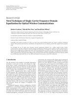
Figure 9: Network topology for ns2 simulations (Sections 6.1–6.3).
0
50
100
150
200
250
Latency (seconds)
50 10 2
Receiver buffer size (packets)
(a)
0
200
400
600
800
1000
1200
1400
1600
1800
2000
Latency (seconds)
50 10 2
Receiver buffer size (packets)
(b)
0
1000
2000
3000
4000
5000
6000
Latency (seconds)
50 10 2
Receiver buffer size (packets)
1GW
2GW
3GW
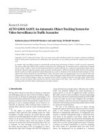
(c)
Figure 10: Effect of receiver buffer size on latency of file transfer for file sizes (a) 5 Kbytes, (b) 42 Kbytes, and (c) 129 Kbytes.
EURASIP Journal on Wireless Communications and Networking 15
Table 2: File sizes in some WSN applications.
Application Blink Sensor acquisition Oscilloscope Count to leds and rfm Multihop broadcast
Size (Kbytes) 5 30 42 111 129
0
20
40
60
80
100
120
140
160
180
Latency (seconds)
25 50 100
Queuing delay (milliseconds)
(a)
0
200
400
600
800
1000
1200
1400
1600
Latency (seconds)
25 50 100
Queuing delay (milliseconds)
(b)
0
500
1000
1500
2000
2500
3000
3500
4000
4500
5000
Latency (seconds)
25 50 100
Queuing delay (milliseconds)
1GW
2GW
3GW
(c)
Figure 11: Effect of queuing delay on latency of file transfer (wired and wireless links bandwidths 100 Mbps and 256 kbps) for file sizes (a)
5Kbytes,(b)42Kbytes,and(c)129Kbytes.
6. Performance Evaluation
We carried out simulations in ns2 in order to evaluate SET
performance. Ta b le 2 shows typical file sizes used in code
updates for some of the sensor network applications. We
selected three different applications with small, medium,
and large file sizes for our simulations, that is, 5, 42, and
129 Kbytes. WSN link bandwidths are typically 56 kbps,
128 kbps, or 256 kbps. In observing the effects of receiver
buffer sizes and queuing delays, we set wired link bandwidth
at 100 Mbps (normal link bandwidth in the Internet), and we
set wireless link bandwidth at 256 kbps. While observing the
effect of link bandwidths, we varied WSN link bandwidths
and kept the Internet link bandwidth constant.
The split-TCP approaches in [7–10] simulate wired-
cum-wireless networks and show considerable TCP perfor-
mance gain when TCP connection is split into two separate
TCP connections. One of these connections is in wired and
other in wireless. In our simulations, we compared SET
performance (multiple gateways) with a single split-TCP. The
results we obtained are encouraging and in agreement with
our assertion. We observed considerable reduction in latency
of file transfer when SET is used. Figure 9 shows the network
topology implemented in our simulations for Sections 6.1,
6.2,and6.3. For clarity of understanding, an end-to-end
path which is split into two TCP sessions (one in wired
and the other in wireless network) is clearly shown in this
figure. We emulated file transfer from sender (CN) in the
16 EURASIP Journal on Wireless Communications and Networking
0
10
20
30
40
50
60
70
Latency (seconds)
25 50 100
Queuing delay (milliseconds)
(a)
0
100
200
300
400
500
600
Latency (seconds)
25 50 100
Queuing delay (milliseconds)
(b)
0
200
400
600
800
1000
1200
1400
1600
Latency (seconds)
25 25 100
Queuing delay (milliseconds)
1GW
2GW
3GW
(c)
Figure 12: Effect of queuing delay on latency of file transfer (wired and wireless links bandwidths 100 Mbps and 1.2 Mbps) for file sizes (a)
5Kbytes,(b)42Kbytes,and(c)129Kbytes.
Internet to receiver (SN)in WSN and measured latency of file
transfer in various scenarios. In this topology, it is assumed
that WSN is the bottleneck of the connection; therefore,
we set bandwidths, delays, and buffer sizes so that the
TCP connections in the Internet and in WSN are expected
to observe. We evaluated SET performance by measuring
latency of file transfer as a metric in our comparisons and
observed the effects of varying (1) receiver buffer size, (2)
queuing delay, and (3) wired and wireless link bandwidths.
In Section 6.4,wesimulatebackgroundtrafficfromCNto
a number of SNs through GWs and observe the effect of
this traffic on a single CN to SN SET data transfer. Finally,
we evaluate SET performance for relatively complex wireless
network topologies in Section 6.5.
6.1. Effect of Receiver Buffer Size. Thelatencyoffiletransfer
for various file sizes was observed by varying the receiver
buffer at SN. We implemented topology of Figure 9 for a
single gateway (GW
1
) with split TCP sessions. We set wired
link bandwidth to 100Mbps and wireless link bandwidth
to 256 kbps. The queuing delays for wired and wireless
networks were kept at 10 milliseconds and 25 milliseconds,
respectively. The buffer size at GW is expected to be large as
compared to SN. We set GW buffer size equal to 100 packets
and varied SN buffer in different ratio as compared to GW
buffer size. Initially, file size for WSN application was set to
5 Kbytes and latency of file transfer was observed. The latency
was then observed for the same file size using SET that sent
striped data through two and three gateways in parallel,
respectively. As shown in Figure 10(a),itisobservedthat
latency of file transfer was reduced considerably when more
gateways were used. We increased SN buffer and observed
latency. Figures 10(b) and 10(c) show SET performance
comparisons with a single gateway for WSN applications
with file sizes of 42 Kbytes and 129 Kbytes, respectively.
Parallelization seems to have maximum advantage when
asymmetry between buffer sizes at GW and SN is low.
Also interesting to note is the fact that when SN receiver
buffer is multiple times small as compared to file size, the
parallelization of TM sessions flows is not very effective.
EURASIP Journal on Wireless Communications and Networking 17
0
100
200
300
400
500
600
700
800
900
Latency (seconds)
256 128 56
Wireless link bandwidth (kbps)
(a)
0
1000
2000
3000
4000
5000
6000
7000
Latency (seconds)
256 128 56
Wireless link bandwidth (kbps)
(b)
0
5000
10000
15000
20000
25000
Latency (seconds)
256 128 56
Wireless link bandwidth (kbps)
1GW
2GW
3GW
(c)
Figure 13: Effect of link bandwidths on latency of file transfer for file sizes (a) 5 Kbytes, (b) 42 Kbytes, and (c) 129 Kbytes.
0
100
200
300
400
500
600
Latency (seconds)
123
Number of sessions
1GW
3GW
(a)
0
2000
4000
6000
8000
10000
12000
14000
Latency (seconds)
123
Number of sessions
1GW
3GW
(b)
Figure 14: Effect of background traffic for file sizes (a) 5 Kbytes and (b) 129 Kbytes.
18 EURASIP Journal on Wireless Communications and Networking
0
100
200
300
400
500
Latency (seconds)
123
Number of wireless hops
1GW
3GW
Figure 15: Effect of WSN topology changes.
6.2. Effect of Queuing Delay in Wireless Link. Figures 11 and
12 show the relationship between queuing delay and latency
of file transfer. The queuing delays in wired and wireless
networks are expected to be different; the queuing delay in
WSNisexpectedtobemoreascomparedtotheInternet.
In order to observe the effect of increased queuing delays
in wireless network, we performed simulations with the
following setup. We set bandwidth in wired link at 100 Mbps
and in wireless link at 256 kbps. The buffer sizes at the
GW and the SN were set equal to 640 Kbytes and 64 Kbytes
respectively. The queuing delays in wireless network were
varied, and observations were taken for different applications
of file sizes, 5 Kbytes, 42 Kbytes, and 129 Kbytes. The results
as shown in Figure 11 for different file sizes are in agreement
with our expectation. The latency of file transfer is reduced
for parallel data transfer through two and further reduced for
three gateways as compared to a single gateway. We conclude
that additional paths for data transfer provide improvement
in performance when WSN is more congested.
The effect of queuing delay is more pronounced and
clear when difference between link bandwidths in wired and
wireless networks is not large. In order to highlight the actual
effect of queuing delay, there is a need to mitigate the effect
of bandwidth asymmetry, which we achieve by increasing the
transmission bandwidth in wireless [30]. Therefore, we set
link bandwidths at 100 Mbps and 1.2 Mbps and observed the
effect of queuing delay. The results are shown in Figure 12.
6.3. Effect of Bandwidth. Bandwidths for wired and wireless
links can vary in different proportions. Wireless networks,
especially WSN, have low linkbandwidthsascomparedto
wired networks. In order to observe behavior of SET in
case of different bandwidths in the two domains, we kept
wired networks at 100 Mbps and varied WSN bandwidth
as 56 kbps, 128 kbps, and 256 kbps. Although latency of
file transfer was observed to be reduced when SET was
implemented as expected; however, an interesting and
positive observation enhanced performance gain from SET
when the difference between link bandwidths in the two
domains are more pronounced and file size is larger. The
observations were taken by varying file sizes in addition to
link bandwidths. We performed simulations for applications
with same file sizes as in previous sections. The results are
shown in Figure 13.
6.4. Effect of Background Traffic. Generally, code updates in
commercial applications of WSN are from CN to a group
of SNs or all SNs in WSN comprising of a large number
of nodes. During code updates in WSN, data trafficfrom
WSN to the Internet is stopped; therefore, we do not consider
the impact of WSN to the Internet traffic. For a single CN-
SN session, the main contributing factor in background
trafficistrafficfromCNtootherSNsinWSNthroughGW.
Figure 14(a) shows background trafficeffect for a file of size
5Kbytes, and Figure 14(b) shows the same for a file of size
129 Kbytes.
In order to observe the effect of background traffic, first,
we simulated data traffic from CN to multiple SNs through
a s ing le G W. We o bse rved t he effect of increasing other
sessions one by one on a single session. This is shown by
upper lines in Figures 14(a) and 14(b).Wethensimulated
multiple SET sessions from CN to a number of SNs (CN
to SN
1
,SN
2
,andSN
3
,simultaneously)andobservedthe
impact on a single SET session (CN to SN
1
). This is shown
by lower line in Figure 14.Asexpected,backgroundtraffic
increases latency both in case of single TCP session as well
SET sessions but a favorable observation is less severe impact
of background traffic in case of SET sessions as compared
to a single split sessions across a single GW. As shown in
Figures 14(a) and 14(b) (upper lines), as the number of
sessions passing through a GW increases, latency of code
update for a single session increases linearly, but for SET
sessions, as the number of sessions increases, as a result of
traffic being directed through a number of GWs, latency
of code update increases at a lower rate. As the number of
sessions across GW increases to a larger number, latency is
expected to increase multiple times at a faster rate for a single
split session, while using an optimal number of GWs, SET
is expected to keep latency within a reasonable limit in the
presence of heavy background traffic.
6.5. Effect of Network Topology. In this subsection, we
observed the effect of SN location within WSN on SET
performance by gradually making the topology complex by
increasingthenumberofhopsinWSN.Asfarasthelocation
of a sensor node is concerned, the effect of this location is
expected to be more pronounced in case of a single session
due to the relative location of gateway. If sensor node is
located near gateway, the impact of number of hops would
be negligible; a node can even be at a one-hop distance
from gateway. But those nodes that are located at a larger
distance from gateway would be affected badly. In SET, since
every sensor node receives data from multiple randomly
located gateways, some of the gateways would be near sensor
node and some far. Therefore, the hop count distance effect
is equally distributed among all nodes in WSN. Figure 15
shows the effect of SN location on CN-SN single session and
on CN-SN SET sessions. The lower curve shows the impact
EURASIP Journal on Wireless Communications and Networking 19
of SN location when SET is used; here, we assume that SN is
located at the same hop-count distance from all GWs. This
will vary, and hence hop-count effect on latency would be
better in SET than what is shown in Figure 15.
7. Conclusion
In this paper we propose architecture for interconnectivity
of the Internet and WSN such that parallel split-TCP
sessions are established through multiple gateways. The data
to be sent is striped across gateways in order to ensure
efficient implementation of TCP in 6LoWPAN. Protocols
proposed earlier for striping TCP across wired-wireless
interconnectivity assume multihomed end hosts and are
not adapted to 6LoWPAN. Although splitting TCP across
gateway for interconnectivity of wired and wireless networks
has shown considerable improvement in performance due
to reduced loss recovery path, it has been observed that
the gateway can become bottleneck due to congestion
when supporting a large number of connections. In case
of 6LoWPAN, the situation can further deteriorate due to
fragmentation and reassembly implemented at the gateway
to cater for MTU mismatch. We present architecture for
TCP management in 6LoWPAN across a number of serving
gateways connecting the Internet host and the sensor nodes.
Through mathematical analysis and simulations in ns2, we
prove that multiple split-TCP sessions managed in parallel
reduces latency in bulk data transfer.
List of Notations
CN: Correspondent node (sender)
GW
n
: nth gateway
SN: Sensor node (receiver)
n: No. of gateways (or No. of TCP flows)
S:No.ofsegmentsforwhichanACKis
sent
R
1
, R
gn
,andR
2
: Transmission rates of CN, GWs, and SN
O: File size in bits
S
1
, S
2
: MSS for wired and wireless networks
M
1
, M
2
: File size (no. of segments) in two
networks
T
1
, T
gn
,andT
2
: Transmission delays for CN, GW
n
,and
SN
RTT
1
,RTT
2
: Round trip times (wired and wireless
network)
P
1
, P
gn
,andP
2
: Processing delay at CN, GWs, and SN
a: No. of SYN retransmissions (wired tcp)
b: No. of SYN/ACK retransmissions
(wired tcp)
c: No. of ACK + SETSYN retransmissions
(wired tcp) segment initial seq. nos.
CN
→ GW
1
d: No. of SYN retransmissions (wireless
tcp)
e: No. of SYN/ACK retransmissions
(wireless tcp)
f : No. of ACK retransmissions (wireless
tcp)
g: No. of SETACK retransmissions
L
1
: Connection establishment latency
(wired)
L
2
: Connection establishment latency
(wireless)
L
CE
: Total connection establishment latency
L
DT
: Latency for data transfer
t
1
:SYN/ACKtimeoutinterval(wired)
t
2
: SYN/ACK timeout interval (wireless)
t
SET
: SETSYN/SETACK timeout interval
m
1a
, , m
1i
: No. of segments sent to GWs from CN
m
2a
, , m
2i
: No. of segments sent from GWs to SN
W
0
: Initial window size
W
sst
: Slow start threshold
W
max
:Maximumwindowsize
K
S
:No.ofwindowswhenW
sst
reached
K
M
:No.ofwindowswhenW
max
reached
B
1
, B
2
:Availablebuffer at CN and at SN
F: Segment out-of-order factor at SN
K
1
:No.ofwindows(dataCN→ GW
1
)
K
2
:No.ofwindows(dataGW
1
→ SN)
W
receive
: Receive window advertized by SN
t
k
: Transmission delay for kth window
T
p
: Processing delay
T
q
: Queuing delay
T
s
:GWservicedelay
T: Average time between packet arrivals
λ
i
: Packet arrival rate for ith path
ρ: GW utilization
N:No.ofTCPflows
Acknowledgment
This research has been supported by Omanchair IT Endow-
ment Fund.
References
[1]V.Tsetsos,G.Alyfantis,T.Hasiotis,O.Sekkas,andS.
Hadjiefthymiades, “Commercial wireless sensor networks:
technical and business issues,” in Proceedings of the 2nd Annual
Conference on Wireless On-demand Network Systems and
Services (WONS ’05), pp. 166–173, Saint Moritz, Switzerland,
January 2005.
[2] Y. Yu, L. J. Rittle, V. Bhandari, and J. B. LeBrun, “Supporting
concurrent applications in wireless sensor networks,” in
Proceedings o f the 4th International Conference on Embedded
Networked Sensor Systems (SenSys ’06), pp. 139–152, ACM
Press, Boulder, Colo, USA, 2006.
[3] L. J. Rittle, V. Vasudevan, N. Narasimhan, and C. Jia, “Muse:
middleware for using sensors effectively,” in Proceedings of
the International Conference on Networked Sensing Systems
(INSS ’05), May 2005.
[4] R. Aguiar and D. Gomes, “Quasi-omniscient networks: sce-
narios on context capturing and new services through wireless
sensor networks,” Wireless Personal Communications,vol.45,
no. 4, pp. 497–509, 2008.
[5]M.R.Butt,Q.Taj,S.Adnan,andA.H.Akbar,“SIPHON,a
mechanism for code update on logical groups using multiple
gateways,” in Proceedings of the 7th International Conference
20 EURASIP Journal on Wireless Communications and Networking
on Networked Sensing Systems (INSS 2010), Kassel, Germany,
June, 2010.
[6] H. Balakrishnan, V. N. Padmanabhan, S. Seshan, and R.
H. Katz, “A comparison of mechanisms for improving TCP
performance over wireless links,” IEEE/ACM Transactions on
Networking, vol. 5, no. 6, pp. 756–769, 1997.
[7] A.BakreandB.R.Badrinath,“I-TCP:indirectTCPformobile
hosts,” in Proceedings of the 15th International Conference on
Distr ibuted Computing Systems, pp. 136–146, June 1995.
[8] A. V. Bakre and B. R. Badrinath, “Implementation and
performance evaluation of indirect TCP,” IEEE Tr ansactions on
Computers, vol. 46, no. 3, pp. 260–278, 1997.
[9] K.Swastik,V.K.Srikanth,F.Michalis,andK.T.Satish,“Split
TCP for mobile ad hoc networks,” in Proceedings of the Sym-
posium on Ad-Hoc Wireless Ne tworks (IEEE GLOBECOM ’02),
Taipei, Taiwan, November, 2002.
[10]X.Fei,J.Ning,H.H.Yao,andK.A.Hua,“Semi-split
TCP: maintaining end-to-end semantics for split TCP,” in
Proceeding s of the 32nd IEEE Conference on Local Computer
Networks (LCN ’07), pp. 303–311, Dublin, Ireland, October
2007.
[11] N. Ehsan and M. Liu, “Modeling TCP performance with
proxies,” Journal of Computer Communications, vol. 27, no. 10,
pp. 961–975, 2004.
[12] A. Sundararaj and D. Duchamp, “analytical characterization
of the throughput of a split TCP Connection,” Tech. Rep.
2003-04, Department of Computer Science, Stevens Institute
of Technology, 2003.
[13] A. Dunkels, T. Voigt, and J. Alonso, “Making TCP/IP Viable for
Wireless Sensor Networks,” in Proceedings of the 1st European
Work shop on Wireless Sensor Networks (EWSN ’04),Berlin,
Germany, January 2004.
[14] T. Braun, T. Voigt, and A. Dunke ls, “TCP support for
sensor networks,” in Proceedings of the 4th Annual Co nfer-
ence on Wireless on Demand Network Systems and Serv ices
(WONS ’07), pp. 162–169, Obergurgl, Austria, January 2007.
[15]A.H.Akbar,K H.Kim,W D.Jung,A.K.Bashir,andS
W. Yoo, “GARPAN: gateway-assisted inter-PAN routing for
6LoWPANs,” in Proceedings of the International Conference
on Computational Science and Its Applications (ICCSA ’07),
vol. 3981 of Lecture Notes in Computer Science, pp. 186–194,
Glasgow, UK, May 2006.
[16] B. Lofti, C. Phil, D. Bharat, and W. I-Jeng, “Design consider-
ations for sensor networks with gateways,” in Digital Wireless
Communications VII and Space Communication Technologies,
vol. 5819 of Proceedings of SPIE, Orlando, Fla, USA, 2005.
[17] A. Jenkins, D. Henkel, and T. X. Brown, “Sensor data collection
through gateways in a highly mobile mesh network,” in Pro-
ceedings of the IEEE Wireless Communications and Networking
Conference (WCNC ’07), pp. 2786–2791, Hong Kong, China,
March 2007.
[18] A. Habib, N. Christin, and J. Chuang, “Taking advantage of
multihoming with session layer striping,” in Proceedings of the
25th IEEE International Conference on Computer Communica-
tions (INFOCOM ’06), 2006.
[19] T. Goff and D. S. Phatak, “Unified transport layer support for
data striping and host mobility,” IEEE Journal on Selected Areas
in Communications, vol. 22, no. 4, pp. 737–746, 2004.
[20] H Y. Hsieh and R. Sivakumar, “A transport layer approach
for achieving aggregate bandwidths on multi-homed mobile
hosts,” in Proceedings of The 8th Annual International Confer-
ence on Mobile Computing and Networking, pp. 83–94, Atlanta,
Ga, USA, September 2002.
[21] M. Zhang, J. Lai, A. Krishnamurthy, L. Peterson, and R.
Wang, “A transport layer approach for improving end-to-
end performance and robustness using redundant paths,”
USENIX, June 2004.
[22] R. Kuschnig, I. Kofler, and H. Hellwagner, “Improving internet
video streaming performance by parallel TCP-based request-
response streams,” in Proceedings of the 7th IEEE Consumer
Communications and Networking Conference (CCNC ’10),
January, 22010.
[23] Y. Sugawara, H. Tezuka, M. Inaba, K. Hiraki, and T. Yoshino,
“E
ffect of parallel TCP stream equalizer on real long fat-pipe
network,” in Proceedings of the 7th IEEE International Sympo-
sium on Networking Computing and Applications (NCA ’08),
pp. 279–282, July 2008.
[24] G. Cheung, P. Sharma, and S J. Lee, “Striping delay-sensitive
packets over multiple burst-loss channels with random
delays,” in Proceedings of the 7th IEEE International Symposium
on Multimedia (ISM ’05), pp. 223–231, December 2005.
[25] M. Junaid and M. Saleem, “Issues of multihoming implemen-
tation using FAST TCP: a simulation based analysis,” Interna-
tional Journal of Computer Science and Network Security,vol.
8, no. 9, 2008.
[26]S.A.Chaudhry,D.J.Won,A.H.Akbar,andK H.Kim,
“Proxy-based service discovery and network selection in
6LoWPAN,” in Proceedings of the 2nd International Confer-
ence on High Performance Computing and Communications
(HPCC ’06), vol. 4208 of Lecture Notes in Computer Science,
pp. 525–534, 2006.
[27] T. Okomoto, G. Hasegawa, and M. Murata, “Dynamic receive
socket buffer allocation at web proxy servers,” IEIC Technical
Report, vol. 102, no. 384, pp. 13–18, 2002.
[28] R. S. Ponmagaland V. Ramachandran, “Link quality estimated
TCP for wireless sensor networks,” International Journal of
Recent Trends in Engineering, vol. 1, no. 1, pp. 495–497, 2009.
[29] N. Cardwell, S. Savage, and T. Anderson, “Modeling TCP
latency,” in Proceedings of the 19th Annual Joint Conference
of the IEEE Computer and Communications Societies (INFO-
COM2000 ’00), pp. 1742–1751, March 2000.
[30] J. Kurose and K. Ross, Computer Networking, A Top-Down
Approach Featuring the Internet, Pearson Education, Upper
Saddle River, NJ, USA, 3rd edition, 2007.
[31] S. William, High-Speed Networks and Internets Performance
and Quality of Service,PrenticeHall,NewYork,NY,USA,2nd
edition, 2002.