The Risk Management of Safety and Dependability_5 pot
Bạn đang xem bản rút gọn của tài liệu. Xem và tải ngay bản đầy đủ của tài liệu tại đây (343.54 KB, 30 trang )
© Woodhead Publishing Limited, 2010
Table 5.5 Diesel engine FMECA
Item Function Local defect System defect
Failure
detection
method
Compensating
provisions
Risk
rank Action
Fuel pipes Supply fuel Fuel leak Fire Fire alarm
(shutdown)
S/D
Fire
protection
system
2 Fit sheaved fuel pipes
with Alarm/shutdown
Lube oil Lubrication
and control
Lack lubrication Hot bearings Oil pressure
temperature
Bearing
temperature
Alarm and
S/D
15 Verify and maintain
standby systems
Cooling
water
Engine and
oil cooling
Lack of cooling Overheating Cooling water
inlet pressure
Inlet and outlet
temperature
Alarm and
S/D
15 Verify and maintain
standby systems
Bearings Locates
moving
parts
Wear High
temperature
Bearing
temperature
Alarm and
S/D
9
Crank case Contains
bearings
Oil mist
concentration
Fire/explosion Crank case
vapour
monitoring
Crankcase
blowout
doors and
fi re traps
3
Exhaust
system
Discharge
outside
Exhaust gas
leak
Pollute engine
room
Observe HVAC system 3 Regular inspection
© Woodhead Publishing Limited, 2010
Table 5.6 Diesel engine FMECA of auxiliaries
Diesel engine auxiliary systems Mode: Normal operation
Item Function
Failure
mode
Failure
cause
Failure
detection
method
Failure effect
Compensating
provisions Rank RemarksLocal System
Starting air Start-up Low
pressure
Compressor
doesn’t
start
Low alarm
pressure
(LAP)
Low pressure Can’t start
engine
Start spare
compressor
15
Cooling
water
Cooling No fl ow
No cooling
Pump fails
Fan fails
LAP
High
temperature
alarm
High
temperature
Engine
overheats
Lube oil
overheats
Start spare
pump
Spare cooler
15 Engine is
safeguarded
by shutdown
Lube oil Lubrication
Cooling
No lube oil
Too hot
Pump fails
Cooling
water fails
LAP
High
temperature
alarm
Low pressure
High
temperature
alarm
Hot
bearings
Start spare
pump
See cooling
water
15
Fuel supply Combustion No fuel Empty tank Low level
alarm
Empty tank Engine
stops
Operating
procedure
15 Operator check
Combustion
air
Combustion No air Filter dirty Delta
pressure
alarm
Low pressure Engine
power
loss
Trend delta
pressure
15 Routine
maintenance
Techniques to fi nd possible risks 109
© Woodhead Publishing Limited, 2010
Added autocontrol PC
shown as
Pressure
vessel
PC
Compressor
PB
Switchgear
Electricity
PB Push button
PC Pressure control
5.3 Diagram of a manual control system for a pressure vessel.
independent of each other. Either of them could stop excessive pressure.
They both have to fail for an explosion to occur. The operator, pressure
gauge, push button and switchgear are said to work in series. They all
depend on each other. If any one fails then they all fail.
The system could be made more reliable by adding automatic pressure
control. This has been shown in Fig. 5.3 as an addition. With this addition,
the system depends on the reliability of the switchgear and the pressure
safety valve. The operation of the switchgear now depends on two inde-
pendent controls (redundancy), one by the operator and the other by the
automatic control (diversity). The system is more reliable as more things
need to fail before there is excessive pressure. A logic fl ow diagram can be
used to illustrate the control system (Fig. 5.4). This shows that the control
logic is the sequential action of the operator, pressure gauge, push button,
switchgear and compressor. If any one of these elements fails then the
whole control system fails. If the control system fails, then the system
depends on the reliability of the pressure safety relief valve on the vessel.
The safety of the manual control system can also be examined by the use
of FMECA (Table 5.7). It will be seen that the risk of an explosion is unac-
ceptably due to the high risk ranking of 4. The risk is reduced by the addi-
tion of an automatic pressure control to the system. This, however, cannot
improve the risk ranking because a coarse qualitative assessment cannot
assess risk reduction. To assess the reduction in risk a quantitative proce-
dure has to be used. This will be examined in the next chapter.
110 The risk management of safety and dependability
© Woodhead Publishing Limited, 2010
Operator
Automatic
pressure control
addition
Pressure
gauge
Explosion
Push button
Switchgear
Pressure
safety valve
5.4 Pressure control logic fl ow diagram.
5.5 Hazard and operability studies (HAZOP)
A HAZOP is a procedure for carrying out a systematic critical examination
of an engineering design to assess the hazard potential due to incorrect
operation or malfunction of individual items of equipment and the conse-
quential effects on the whole plant. It was conceived as a way of improving
safety in the design of chemical plant and is now extensively used in the
design of any type of process plant.
2,3
A team is needed for the study. It
consists of a chairman and a scribe, with representatives from the design
team, operations and maintenance. The actual HAZOP study is a formal
review of the process fl ow diagrams (PFDs), which are conceptual, and
piping and instrumentation diagrams (P&IDs), which are detailed designs.
The method requires the design to be divided up into sections, called
‘nodes’. For each node, a series of questions called ‘guide words’ have to
be answered. This involves the use of a standard worksheet with specifi c
headings for the answers required. At the start of the study session, the
objective of the HAZOP must be stated and a brief background and
purpose of the node under study must be discussed. This will enable the
team to be focused on the objective. The parameters to be considered must
then be decided. The diagram under study should be displayed on the wall
of the study room for all to see. As each line is subjected to the HAZOP,
it must then be highlighted, so that at the end of the study it can be seen
that all lines have been considered. On completion, the study proceeds to
the next node, and so on.
On completion of the HAZOP an initial report is issued, with recom-
mended actions to be taken. A fi nal report is then issued when all recom-
© Woodhead Publishing Limited, 2010
Table 5.7 Starting air manual control system FMECA
Diesel engine starting air control system Mode: Normal operation
Item Function
Failure
mode
Failure
cause
Failure
detection
method
Failure effect
Compensating
provisions Rank RemarksLocal System
Starting
air
system
Controls
pressurised
air
Excess
pressure
Operator None High
pressure
Safety valve
opens
Noise of air
release
12 Add auto-
control
Ditto Pressure
gauge
error
None Ditto Ditto Maintenance
schedule
12 Ditto
Ditto Push
button
failure
Operator Ditto Ditto Manual
operation of
switchgear
12 Ditto, also
operator
training
Ditto Switchgear
failure
Operator Ditto Ditto Ditto 12 Operator
training
Pressure
safety
valve
Release
excess
pressure
Rupture
vessel
Safety
valve
fails to
open
Noise Explosion Damage to
plant and
possible
fatal injury
to operator
Planned
maintenance
of safety
valve
4 In the event
that pressure
control fails
112 The risk management of safety and dependability
© Woodhead Publishing Limited, 2010
mended actions have been implemented. This becomes an audit and record
of what was carried out or, if not carried out, then what was the alternative
and why. The standard worksheet headings and what they mean, together
with the guide words to be used, are listed below. Typical deviations and
an explanation of possible causes explain how guide words can be applied:
Worksheet headings:
Node Item or section of plant studied
Guide word See guide word descriptions
Deviation Study design and identify meaningful deviations of the
guide word
Cause Identify credible causes of the deviation
Consequence Assuming that all protection has failed, establish the
consequence of the deviation
Safeguard Identify safeguards provided to prevent deviation
S-Severity Apply risk-ranking matrix
L-Likelihood Ditto
R-Ranking Ditto
Recommendation Develop recommended action, if needed
Action by Identify who is responsible to take action
Guide words (and their interpretation):
Guide word Typical deviation Explanation
No, None No fl ow Diverted, blockage, closed valve
More Flow More pumps, inward leaks
Pressure Excess fl ow, blockage, closed valve
Temperature Cooling failure
Less Flow, pressure Blocked suction, drain with closed
vent
As well as Contamination Carry over, inward leaks from
valves
Part of Composition Wrong composition of materials
Reverse Flow Backfl ow
Other than Abnormal situations Failure of services/utilities, fi re,
fl ood
Maintenance Isolation, venting, purging, draining
Abnormal operations Start-up, part load, etc.
5.5.1 HAZOP application example
The example to be studied is based on the starting air system. The concept,
as discussed previously, is shown in Fig. 5.3. However, the air system is to
supply utility air for a continuous process plant that must remain in opera-
tion for three years between shutdowns. In consequence, the air system has
Techniques to fi nd possible risks 113
© Woodhead Publishing Limited, 2010
to be installed with a spare compressor package and two air storage pres-
sure vessels (receivers). This will allow critical maintenance of the compres-
sors and inspection of the receivers without the need to disrupt the utility
air supply. This is a simple example as only one node is involved. The object
of the HAZOP must be to verify safe operation and maintenance without
disruption of the air supply. The node under HAZOP study is the air supply
to the receivers. The HAZOP is called a coarse HAZOP, as the study will
be based on a PFD.
The study showed that the closure of any combination of isolating valves
would not lead to over-pressure. All sections of pipe up to the receiver
isolation valves would be protected by the compressor safety valve. The
whole system is of course protected by the pressure control system and the
pressure safety valves on the receivers. It was considered prudent to add
an independent automatic high-pressure shutdown and alarm. This will
improve reliability at little extra cost. The other recommendation was to
add automatic water traps to discharge any water from the receivers and
not to rely on the operators. This will reduce the risk of corrosion due to
water stagnating in the receiver. The isolation and venting of the receivers
was not provided for. Although inlet isolation valves were shown, the vessel
cannot be isolated as the vessel would be pressurised by backfl ow from the
discharge manifold, and so discharge isolation valves have been added.
Although the piping inlet manifold had a pressure gauge, it was considered
prudent to add one to each vessel. A pressure gauge on the vessel will
enable the pressure in the vessel to be monitored during venting down for
maintenance. Due to the high pressure, all instruments need block and
bleed valves to ensure pressure letdown for maintenance. The HAZOP was
carried out on the PFD in Fig. 5.5. The worksheet completed for the study
is shown in Table 5.8. The P&ID that embodies the recommendations of
the HAZOP study is shown in Fig. 5.6.
5.5.2 Other HAZOP applications
The HAZOP procedure was developed by the process industries and the
previous example has demonstrated how it can be applied to a P&ID for a
process system. It is also a useful tool for fi nding weaknesses in any type
of system that can be represented by a block fl ow diagram. It enables the
interface parameters to be explored for the effects of any deviation from
the planned intent. They could be systems that involve the fl ow of materials,
people or data. Alternatively it could be used in the study of a number of
events or activities in a planned sequence. Typical applications are:
• software applications and programmable software systems;
• logistic systems of people and materials;
114 The risk management of safety and dependability
© Woodhead Publishing Limited, 2010
Compressor
Compressor
PC
PB
PC
PB
Receiver
Receiver
Closed valve
Non-return valve
Valve
PB
Push button
PC
Pressure control
PI
Pressure gauge
PSV
PSV
PSV
Pressure safety valve
PI
To
process
5.5 Utility air system process fl ow diagram.
© Woodhead Publishing Limited, 2010
Table 5.8 Utility air system HAZOP worksheet
Session: (date) Node: Air supply to receivers Parameter: Air fl ow Intention: Maintain min./max. pressure
GW Deviation Cause Consequence Safeguard Rank Recommendation By
No No fl ow Compressor or
receiver
valve closed
No air supply Operator 15 Lock valve in open
position
Piping
More More fl ow Excess air
supply
Over-pressure Compressor
pressure
control
15 Add high-pressure trip
as extra safety
measure
Design
Less Less fl ow Compressor
defect
Lose pressure Start spare
compressor
15 Add to control sequence
and alarm operator
Ditto
As well
as
Impurity Moist air Water in receiver Operator
blowdown
5 Air–water trap Ditto
Other
than
Maintenance Compressor Close compressor
isolation valve
Permit system 8 Use locked shut valve Piping
Receiver Release air
pressure
None 4 Add exit valve, vent
valves and pressure
gauge
Ditto
Instruments Ditto No vent and
isolation valves
6 Add vent and isolation
valves
Ditto
More More pressure Pressure
control fails
System
over-pressure
Compressor and
receiver safety
valve
8 See more fl ow above
116 The risk management of safety and dependability
© Woodhead Publishing Limited, 2010
PAHH High pressure alarm/
trip
Compressor
Compressor
PC
PB
PC
PB
Receiver
Receiver
Closed valve
Non-return valve
Valve
PB
Push button
PC
Pressure control
PI
Pressure gauge
PRV
PRV
PRV
Pressure safety
valve
To
process
PI
PI
PAHH
PI
Trap
Trap
PAL
PAL Low pressure
alarm
5.6 Final piping and instrument diagram.
Techniques to fi nd possible risks 117
© Woodhead Publishing Limited, 2010
• assessment of administrative procedures;
• assessment of other systems and devices.
In the HAZOP of logistics where time or sequences are involved, other
additional guide words are needed, such as:
• early;
• later;
• before;
• after.
The other guide words may not be applicable and can be ignored. The
IEC standard for hazard studies provides examples illustrating the above
applications.
3, 5
5.6 A cautionary example
The effectiveness of any hazard analysis depends entirely on the experience
and creative imagination of the team doing the investigation. The proce-
dures only impose a disciplined structure to the work. The Concorde super-
sonic airliner that crashed at Paris in 2000 is a good example of this. During
take-off a fuel tank in the wing was ruptured. The escaping fuel was ignited
and then the plane caught fi re and crashed. The engineers had considered
all failure modes in the design and the fuel tank should not have ruptured.
The event that was not foreseen was the possibility that an object could
strike the underside of the fuel tank and cause a hydraulic wave to be
transmitted to the upper side of the fuel tank. It was the refl ected hydraulic
wave that then caused the underside of the fuel tank to rupture. If the fuel
tank had not been completely full there would not have been a refl ected
hydraulic wave. For take-off on a long journey the tanks were of course full.
No one had thought of this possibility; it just demonstrates how much
imagination is needed to ensure that all failure modes are identifi ed. Some-
times it is just too much to expect, as with Concorde. Making provisions to
avoid the hazard by design solved the problem. The tyres were redesigned
to avoid bursting and shedding large enough debris to cause damage to the
fuel tanks. The fuel tanks were lined with a material that could absorb
hydraulic shock waves and self-seal if punctured.
5.7 Summary
This chapter has shown how processes and systems can be broken down
and analysed to fi nd hazards to safety and reliability. The techniques of
using ‘What if’, producing block fl ow diagrams and how to apply FMEA
have been demonstrated. A method of risk ranking to qualify risk has been
118 The risk management of safety and dependability
© Woodhead Publishing Limited, 2010
provided. These methods have been used on an air system, which was
developed from an initial PFD to a fi nal P&ID using HAZOP. It has also
been shown that fi nding hazards and reducing risk depend entirely on the
abilities of the team assigned. These techniques can be applied to a whole
range of situations for many different industries. The work should be a
challenge to the creative imagination of any engineer. There are other
techniques in use that are listed in published codes of practice.
4
In high-risk
situations it has also been shown that there will be a need to quantify the
risk to safety, and calculate its reliability, for any plant or system. This is
especially true if the effects of improvements need to be judged or alterna-
tive measures need to be compared. These matters will be dealt with in the
chapter that follows.
5.8 References
1 bsi iso iec 60812, Analysis Techniques for System Reliability – A Procedure for
Failure Mode and Effects Analysis (FMEA)
2 chemical industries association (1992) A Guide to Hazard and Operability
Studies, London
3 bs iec 61882: 2001, Hazard and Operability Studies (HAZOP Studies) –
Application Guide
4 bs 31100: 2008, Risk Management – A Code of Practice
5 bs iec 60300-3-9, Dependability Management – Risk Assessment of Technological
Systems
© Woodhead Publishing Limited, 2010
119
6
Safe enough? Methods and procedures for
evaluating and reducing risk in the design of
processes, plant and machinery
Abstract: This chapter is intended to provide suffi cient introduction to
the subject matter for managers and engineers to deal with simple
situations in industry and to communicate with safety specialists. The
concept of ‘as low as reasonably practicable’ (ALARP) will be explained
and what degree of risk is acceptable or expense is needed to comply.
For a qualitative assessment the use of the Bow Tie analysis procedure
is explained showing the multiple levels of controls required to reduce
risk and the management system needed to ensure its effectiveness. The
use of failure rate data and its application to simple systems is given.
From this fault tree analysis is used to evaluate a pressure control
system. The importance of testing standby units for hidden failures and
the folly of neglecting this and the value of redundancy is discussed.
Key words: ALARP, value of life, acceptable risk, Bow Tie analysis,
human error, TESEO, preventative, recovery, engineering, system,
human, component failure, probability, failure rate, factors, MTTF,
MTTR, redundancy, series systems, partial redundancy, binomial
distribution, hidden failure, test interval, hazard rate, demand rate,
availability, unavailability, common mode, FTA, exposure risk, SIL.
6.1 Introduction
The law requires that employers have a duty of care to ensure the health
and safety of their employees and the public who could be affected by their
activities. With the Corporate Manslaughter and Corporate Homicide Act
(2007) in place, corporate management will need to understand what has
to be done to fulfi l their duty. The risk of an accident can never be zero.
So what is safe enough?
When there are no accidents!
The means by which accidents can be reduced and the estimation of their
probability of occurring can be quite complex. In some situations an expert
knowledge of the industry, the situation and the use of complex mathemat-
ics is needed. However, the intention here is to provide the basic principles
in suffi cient detail to enable managers and engineers to understand the
subject. This will enable those who design plant and machinery to work
120 The risk management of safety and dependability
© Woodhead Publishing Limited, 2010
with the specialist safety engineers in compliance with HSE regulations. In
the management of operations the measures to control safety have to be
appreciated and maintained to ensure that they are effective. Corporate
management may engage consultants to aid them in this task, but as they
cannot subcontract responsibility, they will have to take responsibility for
the work and understand what is being done.
1
In the UK the law requires the risk of an accident to be reduced as low
as reasonably practical (ALARP). This means that some common sense
judgment is allowed. However, it should be noted that the UK and The
Netherlands are the only ones in the EU that allow a risk-based assessment
to determine what is acceptable. To manage risk, a risk assessment needs
to be made to determine what measures to control or mitigate them are
needed. In most situations these measures can follow established industrial
practice. In other situations it has been established that a cost-based analy-
sis (CBA) of the investment to save life is acceptable.
2
Implied values to
prevent a fatality in the UK are (2004 values):
• health service << £1 million;
• roads < £1 million;
• industry £1 million;
• railways £1.3 million.
In other countries the thought of any residual risk is socially and legally
unacceptable. Even in the UK, should a case be brought to court, this may
well be the attitude of the jury. Any defence that relies on complicated
technical issues will probably not be understood or accepted. Where the
risk can be quantifi ed, its acceptability is shown in Table 6.1, which com-
pares fatal injury rates against risk acceptance criteria.
The fatal injury rates in the table illustrate how the public will accept a
much higher risk of their own choosing but will be intolerant of any imposed
risk.
3
What is acceptable depends on perspective, which is as follows:
• Personal risk, people may sometimes take enormous risks.
• Societal risk, what is acceptable depends on public opinion.
• Business risk, the possible loss of capital assets is often overlooked.
• ALARP risk, to health and safety, often linked to business risk.
For industry the risks to health and safety that are between a thousand and
one in a million are only tolerable if they are shown to be ALARP.
4
However,
if a disaster occurs and it involves the public it is also a societal risk and
may become an emotional issue. A risk of considerably less than one in a
million may then be demanded. The estimation of probability is based on
judgement, the calculation of probability is based on statistical data. Statisti-
cal data is based on past history that may or may not be applicable to the
circumstance predicted. It is important to remember the old adage, ‘Lies,
Methods and procedures for evaluating risk 121
© Woodhead Publishing Limited, 2010
absolute lies and statistics’. Therefore the lines of demarcation given in the
table are target guidelines.
6.1.1 Example of ALARP
For a building that requires roof maintenance access, the following alterna-
tive facilities to be provided can be considered:
1. permanent internal stairway up to the roof with railings and hoist
facilities;
2. permanent external wall ladders with access platforms and hoist
facilities;
3. no facilities, use contracted scaffolding/mobile equipment when needed;
4. no facilities, just use a ladder when needed;
5. leave it to the owner’s maintenance department.
Option 4 is against the law. The law requires a risk assessment. The hazard
is a man falling to the ground. The consequence is death or injury, which
depends on:
• the height of the roof;
• a hard or soft landing.
Table 6.1 Acceptable risk of an accident
Activity
Fatal injury rate
per 10
−5
persons
per year
Risk acceptance
criteria for industry
Probability
per million
Heavy smoking 500 Unacceptable
Rock climbing 400 Ditto
Mining 100 Only just tolerable for
workers but not any
exposed public
1000
Road user 10 Only just tolerable for
the public
100
Agriculture, hunting,
forestry and fi shing
7.5 Tolerable, but needs
justifi cation
75
Construction 4.7 The probability per
million must be
ALARP
Extraction and utility
supply
3.2
Manufacturing 1 10
Services 0.4 4
0.1 Acceptable 1
Lightning 0.01 0.1
122 The risk management of safety and dependability
© Woodhead Publishing Limited, 2010
The probability of a fall will depend on the:
• required frequency of access;
• duration of access;
• span of reach required to complete the work;
• experience and age of the worker.
The choice made will depend on a number of factors:
• The fi rst option will have the highest cost, and each following option
will cost less. How much money must be justifi ed?
• The cost then has to be balanced against the risk and consequence of a
man falling.
• The risk of falling depends on how often there is need to go on the roof.
If there is a need to go on the roof only once in every fi ve years, it clearly
is not reasonable to insist on the expense of the fi rst two options. Once a
year, perhaps, could justify option 2, and perhaps once every few weeks,
option 1. Clearly option 4 can only be considered if it is a low roof that is
only a few metres above ground. There are many work situations where
humans have to be considered within a system or work process. In these
cases the risk can be analysed by use of ‘Bow Tie’ analysis.
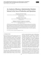
6.2 Bow Tie analysis
Bow Tie analysis is based on focusing on an event that will result in an unde-
sired outcome. An accident in a test facility will be used as an example to
illustrate this (Fig. 6.1). The test facility consisted of liquefi ed natural gas
Tank Tank
Pump
Ladder
6.1 A pump test facility.
Methods and procedures for evaluating risk 123
© Woodhead Publishing Limited, 2010
(LNG) tanks located adjacent to a pit, in which vertical multi-stage pumps
could be installed for test. The installation had been in use for some time
without incident. On the day of the accident, an LNG pump was being sub-
jected to a 24-hour proof test. After running without problems during the
day, it was left to continue running during the night, attended by two test
observers. In the morning they were found dead at the bottom of the test pit.
They died due to lack of oxygen. There was no requirement for the observers
to go into the pit and it was thought that one had entered to pick something
up and his friend went after him when he collapsed. In the design of the test
facility, the danger of falling into the pit was recognised and the pit was safe-
guarded with railings. A steel ladder was provided to access the bottom of
the pit. This was required during the installation of a pump for the test.
Any leakage of LNG will fl ash off into gas in the atmosphere. At fi rst the
gas will be cold at its boiling point of −160 °C and it will be heavier than
air. As it warms up to ambient temperature it will become lighter than air
and becomes displaced by air. During the cooler night temperature the cold
methane gas was not completely displaced and the amount of air in the pit
was not suffi cient to support life. Any atmosphere with even only 60% of
the normal oxygen content could cause a person to faint, lose consciousness
and die. The event to be avoided was to enter the pit. This can be shown as
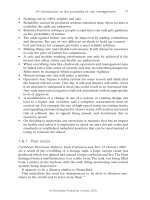
a Bow Tie diagram (Fig. 6.2).
The circle at the centre is the undesired top event. By linking the hazards
and the consequences through a series of event lines it is possible to develop
a diagram illustrating the routes to accidents. Preventative and recovery
controls can then be considered for each line. In general these will consist
of engineered, system and human defences in order to provide an in-depth
Injury
Sense of danger
Falling in
Climb down
ladder
Railings
Faint
Enter pit
Die
Hazards
Consequence
6.2 Pre-accident Bow Tie diagram.
124 The risk management of safety and dependability
© Woodhead Publishing Limited, 2010
safety system. They are the barriers to an accident and each additional
barrier reduces the probability of the undesired event (Fig. 6.3). However,
each component of the safety system can also fail and a ‘What if’ procedure
can be used to identify the measures needed to prevent this (Tables 6.2 and
6.3). There is a danger that in time complacency sets in and individual bar-
riers fall into disuse and so an integrated safety management system (ISMS)
must be put in place to prevent this.
These are simple engineered systems with human interfaces that are
based on a qualitative risk assessment that follows established practice.
ALARP is based on doing as much as is considered reasonable. In other
more complex systems, as found in the nuclear and petrochemical indus-
tries, ALARP has to be based on a quantitative risk assessment. One
important element is human error.
6.3 Human error
Human error can never be totally eliminated and there has been much
research carried out on how to quantify this risk. Research has established
there could be as many as 38 factors to be considered at fi ve different cogni-
tive levels. More recently a tool for human reliability assessment, nuclear
action reliability assessment (NARA), has been developed from a human
error reduction techniques procedure (HEART). This identifi es some 14
generic task types (GTT) with their human error probabilities (HEP). The
generic HEP then has to be adjusted by assessing the proportion of affect
(APOA) and the applicability of 18 error-producing conditions. This pro-
Preventative
Recovery
Engineered
System
Human
Climb down
ladder
Falling in
Faint
Injury
6.3 Post-accident Bow Tie diagram.
Methods and procedures for evaluating risk 125
© Woodhead Publishing Limited, 2010
cedure requires an intimate experience and knowledge of the tasks involved
and the characteristics of the workforce, and serves to show the complexity
of the task.
As an introduction to the subject, a simple method, as devised by Bello
and Columbori and known as TESEO, will be used.
5
It only uses fi ve factors
as set out in Table 6.4. Because of this it is not considered to be accurate,
but is suitable for assessing operator response in a control room type situ-
ation. The method can be applied on the case history referred to in Chapter
4, the Kegworth M1 air disaster, which was an example of poor information.
In this case, the pilot was faced with the indication of high vibration from
one of two engines. It was not clear from the instrument which engine, and
the wrong one was shut down. The vibrating engine lost power and the
Table 6.2 Pre-accident: falling into the pit control measures
Hazard of falling into the pit
Preventative/recovery ‘What if’ measures
Preventative What if Action
Engineered
Railings Climb over or go through
2.5 metre fence with
small mesh screen
Failure due to disrepair Instigate maintenance plan
System
Maintain fence and
signs
Maintenance defi ciency Regular inspection
Failure to inspect Audit to ensure compliance
Human
Warning signs Missing or not legible Maintenance system
Instruction and
training
Not provided Audit to ensure compliance
Recovery What if Action
Engineered
Rescue hoist Failure due to disrepair Instigate maintenance plan
System
Maintain hoist and
alarm
Maintenance defi ciency Regular inspection
Failure to inspect Audit to ensure compliance
Rescue team Ineffective Regular drills
Human
Double manning One off sick Supervisory check
Provide alarm Failure due to disrepair Instigate maintenance plan
Instruction and
training
Not provided Audit to ensure compliance
126 The risk management of safety and dependability
© Woodhead Publishing Limited, 2010
Table 6.3 Post-accident: hazard of entry into pit control measures
Hazard of entry into pit
Preventative/recovery ‘What if’ measures
Preventative What if Note
Engineered
Locked gated access Access to key Key under control of safety
offi cer
Broken lock or gate Instigate maintenance plan
System
Maintain locked gate Maintenance defi ciency Regular inspection
Failure to inspect Audit to ensure compliance
Work permit system Failure to enforce
Human
Test for gas before
entry
Dysfunctional
instrument
Impose test schedule
Instruction and
training
Not provided Audit to ensure compliance
Recovery What if Note
Engineered
Rescue hoist Failure due to disrepair Instigate maintenance plan
System
Maintain hoist and
alarm
Maintenance defi ciency Regular inspection
Failure to inspect Audit to ensure compliance
Rescue team Ineffective Regular drills
Human
Recovery harness Defective Supervisory check
Breathing apparatus Dysfunctional Regular inspection and test
Provide alarm Failure due to disrepair Instigate maintenance plan
Instruction and
training
Not provided Audit to ensure compliance
plane crashed. To apply the TESEO assessment of probable human error,
K factors need to be selected from Table 6.4:
Type of activity is not routine K
1
is 0.1
Temporary stress factor for non-routine activity K
2
is 1
(As the pilot was alarmed and not trained,
he reacted quickly.)
Operator qualities: average knowledge and training? K
3
is 1
Activity anxiety factor: situation of potential emergency K
4
is 2
Activity ergonomic factor: tolerable interface? K
5
is 3
Probable human failure can be calculated as:
Methods and procedures for evaluating risk 127
© Woodhead Publishing Limited, 2010
Table 6.4 TESEO probability parameters
Type of activity factor
K
1
Simple routine 0.001
Requiring attention, but routine 0.01
Not routine 0.1
Temporary stress factor, for routine activities
K
2
Time available, in seconds: 2 10
10 1
15 0.5
Temporary stress factor, for non-routine activities
K
2
Time available, in seconds: 3 10
30 1
45 0.3
60 0.1
Operator qualities
K
3
Carefully selected, highly trained 0.5
Average knowledge and training 1
Little knowledge and training 3
Activity anxiety factor
K
4
Situation of grave emergency 3
Situation of potential emergency 2
Normal situation 1
Activity ergonomic factor
K
5
Excellent working conditions and a well designed interface 0.7
Good working conditions and a good interface design 1
Tolerable working conditions and a tolerable interface design 3
Tolerable working conditions and a poor interface design 7
Poor working conditions and a poor interface design 10
P = K
1
× K
2
× K
3
× K
4
× K
5
[6.1]
P = 0.1 × 1 × 1 × 2 × 3
P = 0.6
This means that the probability of error is six times out of ten occasions,
a very high risk. Depending on how the K factors are chosen, P could be
1 or even more than 1. This means that, statistically, an error is bound to
occur as borne out by the accident.
It is of interest to note the generic probability of human failure in other
situations. In the case of the nuclear industry it is suggested that for:
• routine, good feedback and time to make use of it, and
a good appreciation of hazard 0.0001
• routine, simple 0.00007
128 The risk management of safety and dependability
© Woodhead Publishing Limited, 2010
• responding to an alarm with the need for a simple action 0.0004
• non-routine complicated 0.2
Whereas for operators of machines controlled by programmable computer
control systems, it is suggested that the following could apply:
• routine, good feedback and time to make
use of it, and a good appreciation of hazard range (1 to 10) × 10 ^ 6
• routine, simple 0.001
• non-routine complicated 0.1
In the process industries for simple operations a value of 0.00036 is often
used. Every time the operator carries out an operation there is a 0.00036
chance of an error. Or for every million actions there will be 360 mistakes.
This is similar to that suggested for the nuclear industry but is much less
than that for operators of programmable computers. This shows that the
probability of human error depends on the qualities of the operator and
the work environment. It also confi rms that the reliance on one person to
carry out any operation or maintenance procedure has a high probability
of error. This mirrors the experience found in manufacturing industry where
at least two persons are required to check any critical piece of work and
additional measures (redundancy) are needed to control risk.
6.4 Redundancy
An operator needs to be supervised so that any human errors can be
noticed and corrected. An automatic control system has to be supervised
by an operator in case it goes wrong. Banks and hospitals have an emer-
gency generator as a backup in case of a supply power failure. A cruise ship
is installed with extra engines as spares, ready to take over if an engine fails
and shuts down. The ambulance services have extra ambulances on call to
cope with peak demand and if an ambulance breaks down and needs
servicing.
These are all measures to provide redundancy to prevent a failure having
an effect on a service or operation. The provisions are of no use until they
are needed. The value of having redundancy is appreciated when things go
wrong regularly or even once every few years. The danger is when they
never seem to be needed. Management then tend to view them as an over-
head whereas in reality they should be viewed as insurance. Why have
money tied up in something that is not used? Maybe over decades nothing
happens and so they receive inadequate investment until eventually there
is a disaster. New Orleans (Chapter 1) is such an example; another prime
example is Bhopal in India where the release of a toxic gas affected the
health of a whole city for generations up to the present day. It is important
Methods and procedures for evaluating risk 129
© Woodhead Publishing Limited, 2010
therefore for management to keep the probability of failure in mind and
to understand the principle of redundancy and its affect. Even worse, is
taking the risk and then not to have recovery plans in place. To sound an
alarm and to evacuate the city would have mitigated the disaster.
6.4.1 Parallel systems
Parallel systems are the mathematical concept of redundancy, where there
is more than one way of fulfi lling a function. For example, a man has four
vans at his disposal and has an urgent delivery. If one fails to start, he has
three others to try. He has 300% redundancy. They must all fail before he
is unable to go. The probability of failure is less than for only one van. This
can be illustrated by a process block fl ow diagram (Fig. 6.4) that shows the
process for delivery. There are four ways to effect delivery and all must fail
for a failure to deliver. The concept can also be shown as a logic block
diagram (Fig. 6.5), which shows how delivery can fail. It shows that Van 1
and Van 2 and Van 3 and Van 4 must fail for a failed delivery. This means
that the probability of a failure must be less than if there is only one van.
The probability of failure for a parallel system can be evaluated by the
multiplication of the probabilities:
Parallel (and gate) multiply: P
system
= P
1
× P
2
× P
3
× P
4
[6.2]
Van 1 Van 2 Van 3 Van 4
Delivery
6.4 Parallel process block fl ow diagram.
P
3
P
4
Failure to deliver
and
P
1
P
2
6.5 Parallel logic block diagram.
130 The risk management of safety and dependability
© Woodhead Publishing Limited, 2010
As P, the probability of failure, is a decimal fraction a parallel system is
more reliable and less prone to failure. In industry three parallel control
systems are used for airliners and four for safety critical controls for nuclear
plants.
6.4.2 Partial redundancy
The preceding section showed how to evaluate parallel systems. For the
example given, only one van was needed and there were three spare
vans available (300% redundancy). On another day there could be a dif-
ferent situation. Three vans are in constant use and there is one van held
as a spare (33.3% redundancy). Because all the vans are identical, which
ones are used is of no concern. Vans A, B and C are no different to Vans
C, B and A. The different vans available are a combination, and not a
permutation. In order to calculate the probable failure to deliver, use
must be made of the binomial distribution equation. This is developed as
follows:
• Number of vans: A B C D
• For the system to fail, any two vans must break down. These failure
modes are:
• Combination 1: AB, AC, AD
• Combination 2: BC, BD
• Combination 3: CD
By examination, it can be seen that there are six possible combinations of
two vans failing that can cause delivery failure. The chance that there are
only two vans depends on the probability of failure of any two vans and
the reliability of the other remaining two vans to operate. That is:
P
2
× (1 − P)
2
[6.3]
This is for any one combination and, as there are six combinations, then the
probability for any two vans to fail will be:
6 × P
2
× (1 − P)
2
[6.4]
The general equation for a binomial distribution, which caters for any
number of combinations, is:
P of system = {n! / [r!(n − r)!]} P
r
(1 − P)
(n−r)
[6.5]
where
n is the number of items available, 4 in the example
r is the number required, 2 in the example
P is the probability of failure of each item.
Methods and procedures for evaluating risk 131
© Woodhead Publishing Limited, 2010
Note that the fi rst term is the number of combinations.
(4 × 3 × 2 × 1) / [2 × 1(4 − 2)!] = (4 × 3) / (2 × 1) = 6
as derived above. However, in calculating failure combinations, it is impor-
tant to be sure to identify all failure modes, bearing in mind that failure is
random and is by chance. In the case of the delivery vans where there are
four but only three are needed, the failure modes when three are not avail-
able will be:
1. 4 out of 4 failed or
2. 3 out of 4 failed or
3. 2 out of 4 failed.
All these failure modes will be unacceptable and therefore the probability
that they can occur must be calculated; because none are acceptable, they
constitute a series system, as characterised by or logic, and the results of
each failure mode must be added together.
Redundancy is an investment with no return until it is needed. In some
cases it may be possible to consider partial redundancy. This is especially
true when dealing with fl eet numbers. If six engines are needed to drive a
ship it will be found, and borne out from experience, that 50% spare is the
optimum. A third spare is the minimum to be considered, anything less has
no effect on reliability.
6.5 Series systems
As has been discussed preventative measures will usually need an engineered
element to ensure safety. For example to avoid over-pressure, a manual
control system will consist of an operator, a gauge, a push button and switch-
gear. The operator watches the gauge and presses the push button to stop a
compressor that is feeding a vessel. This is a series system. There are four
elements and failure of any one will cause the system to fail. This can be
represented by a process block fl ow diagram, where P is the probability of
failure (Fig. 6.6). The sequence will come to a stop if any item fails. It can
also be said that the failure of P
1
or P
2
or P
3
or P
4
would cause failure.
There are four chances of failure. This can be shown as a logic block
diagram (Fig. 6.7) that shows the events that can cause failure.
As there are four ways in which failure can occur, then there are more
chances of failure. This means that the probable failure has to be greater
than any one of them individually. Therefore for series systems the prob-
abilities must be summed. A series system is less reliable and more prone
to failure:
Series (or gate) sum: P
system
= P
1
+ P
2
+ P
3
+ P
4
[6.6]