The Risk Management of Safety and Dependability_6 pot
Bạn đang xem bản rút gọn của tài liệu. Xem và tải ngay bản đầy đủ của tài liệu tại đây (297.52 KB, 30 trang )
Methods and procedures for evaluating risk 137
© Woodhead Publishing Limited, 2010
• Third-level events: switchgear fails or pressure control fails.
• Fourth-level events: manual control fails and auto-pressure control fails
and high-pressure alarm/shutdown fails.
• Manual control fails: because operator fails or pressure gauge fails or
push button fails.
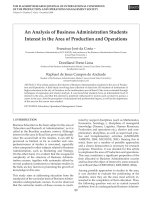
The drawing for the fault tree is shown in Fig. 6.9 and has been constructed
to avoid a common mode failure. To demonstrate common mode failure it
can also be constructed as follows:
• Second-level events: pressure relief valve fails (basic event) and
pressure control fails.
• Third-level events: manual control fails or auto-pressure control fails or
high-pressure alarm/shutdown fails.
• Manual control fails: because operator fails or pressure gauge fails or
push button fails or switchgear fails.
• Auto-pressure control fails: because auto-pressure control fails or
switchgear fails.
• PAHH fails: because high-pressure alarm/shutdown fails or switchgear
fails.
Valve
leak
Transfer
symbol
Oil leak
Ignition
Pump
leak
or
Event to be
developed
and gate symbol
and
Oil fire
Event symbol
or gate symbol
Basic event symbol
6.8 Development of events leading to a fi re.
138 The risk management of safety and dependability
© Woodhead Publishing Limited, 2010
Here the same switchgear appears in three places; this is called a common
mode failure. If not corrected, it will result in the failure of the switchgear
being accounted for too many times.
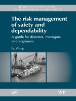
An evaluation of the pressure control system fault tree in Fig. 6.9 shows:
Manual control system probable failure P
1
= A + B + C
Automatic control system probable failure P
2
= E × F
Pressure control system probable failure P
3
= P
1
× P
2
Compressor shutdown probable failure P
4
= P
3
+ D
Probable explosion P
5
= P
4
× G
Operator Pressure gauge Push button
A C
B E
F
Manual
control P
1
or
Pressure
relief valve
Compressor S/D P
4
G
Explosion P
5
and
and
or
D
Pressure control P
3
and
Auto-
control P
2
Switchgear
Auto-control
PAHH
shutdown
6.9 FTA air pressure control system.
Methods and procedures for evaluating risk 139
© Woodhead Publishing Limited, 2010
For an annual operation time of 8000 hours the evaluation of the system is
shown in Table 6.7. The probabilities of failure for the different pressure
control confi gurations are shown in the table, together with the resultant
probability of an explosion.
The results show that the pressure relief valve needs to be tested every
1000 hours for the explosion to be within the tolerable range of risk as given
in Table 6.1. The table also shows that the probability of the control system
failure progressively improves as more safeguards are added. However, it
has to be noted that the reliability of the shutdown system is limited by the
failure probability of the circuit breaker. Any control system failure prob-
ability that is less than that for the circuit breaker will have little effect on
the probability of failure of the shutdown system. This can also be seen
from the fault tree diagram (Fig. 6.9) and is demonstrated as follows:
The PAHH has a P value of 4000/10
6
= 0.002 for T = 1000 h.
This gave a manual + auto-control + PAHH probability P = 0.02895 ×
0.00036 = 0.00001.
If the test interval of PAHH is increased by fi ve times to T = 5000 h then
the P value would be 0.01. The manual + auto control + PAHH would
then be 0.00005.
Table 6.7 Quantitative risk of an explosion
Item Symbol Gate P Evaluation
Operator A or 0.000350
Pressure gauge B or 0.027 P
1
= A + B + C
Push button C or 0.0016 P
1
= 350 + 33 + 0.8
Manual control P
1
0.02895
Auto-pressure control
(PC)
E and 0.092
PAHH shutdown F and 0.004 FDT when T = 1000
Auto-PC + PAHH P
2
0.00036
Manual + Auto-PC +
PAHH
P
3
0.00001 P
3
= P
1
× P
2
Circuit breaker D or 0.0012
Compressor shutdown
manual
P
4a
0.0277 P
4a
= P
1
+ D
Compressor shutdown,
auto-PC + PAHH
P
4b
0.00156 P
4c
= P
2
+ D
Compressor shutdown,
manual + auto-PC +
PAHH
P
4c
0.00121 P
4d
= P
3
+ D
Pressure relief valve G and 0.085 No testing
Pressure relief valve G
1
0.0055 FDT when T = 1000
Explosion with P
4c
P
5
= 0.00121 × 0.085 = 0.000103 (P
5
= P
4c
× G)
Explosion with G
1
P
5
= 0.00121 × 0.0055 = 0.0000067 (P
5
= P
4c
× G
1
)
140 The risk management of safety and dependability
© Woodhead Publishing Limited, 2010
The probability of failure of the shutdown system would then be
0.0012 + 0.00005 = 0.00125.
It can be seen that the probable failure of the PAHH does not seriously
affect the chance of an explosion. To understand the situation more fully,
the concept of ‘demand rate’ is needed. The automatic pressure control has
a probable failure of 12/10
6
h. That is every 83 333 hours. The PAHH, there-
fore, only probably needs to function once every 83 333 hours. Although
there is a temptation to further extend the testing interval, it is prudent to
keep it below half the demand interval as a maximum. On the other hand
the test interval of the pressure relief valve has a signifi cant affect on the
probability of an explosion and must be strictly enforced.
Examination of the fi gures show that the probability of failure of the
automatic pressure control is 3000 times greater than when there is a
backup PAHH. The calculations also show that the PAHH has to function
every 8333 hours. If the plant is shut down every 8000 hours during the
summer then the PAHH is never activated. This is a very important point.
To the operators, the PAHH is useless because it never does anything, and
yet it has such signifi cance for pressure control system reliability. It has
been recorded that in one plant there was just such a situation. The backup
device was causing spurious trips. The plant functioned quite well without
it and so it was disconnected. There were no operating problems and it was
forgotten about until a few years later, when the event that never happens,
happened. There was no backup. Disaster struck.
The analysis so far has been based on continuous operation. The air
system, depending on the type of operation, could be operated for a short
period of time for a number of times in a year. An air starting system for
a diesel engine is used and then recharged, ready for the next start-up
requirement. As an example, the case of an air starting system on a ferry
ship can be considered. Demand rate is then the number of times it is
needed per year of 8000 hours. Hazard rate is the number of times it might
fail. So assuming that:
Compressor shutdown demand rate D: 300 times a year or 300/8000 h
Compressor shutdown failure probability is 0.00121
Shutdown hazard rate H = 0.00121(300/8000) = 0.000045
Pressure release valve (PRV) demand rate D
2
: 45/10
6
h
PRV failure probability (G from table): 0.0055
PRV hazard rate H = 0.0055(45/10
6
) = 0.25/10
6
h. Less than one in a
million probability.
The above also shows the importance of applying as many redundant
measures as possible to reduce the risk of failure, which is a well-established
industrial practice. But it cannot be emphasised enough the importance of
ensuring the maintenance of each element, which is so often neglected in
Methods and procedures for evaluating risk 141
© Woodhead Publishing Limited, 2010
practice. The analysis also allows study of the effects of the selected test
intervals. This is important as it affects the maintenance costs, which must
be balanced with safety. The analysis has provided an estimate of the prob-
ability of an explosion. To complete the risk assessment it will be necessary
to consider the consequences.
In the example the FTA of a pressure control system and the possible
risk of an explosion has been found. The hazard has been identifi ed and
the risk of an explosion quantifi ed. The acceptability of the risk will also
be dependent on an appraisal of the consequences.
The following questions need to be answered:
1. Where is the hazard located?
2. What will be the consequential damage?
3. What is the risk from the consequential damage?
4. How many people could be in the vicinity?
5. Would the public be affected?
6. What injuries could be sustained?
Location
The receiver is located in a compressor building. The building has one wall
adjacent to a public road with a busy footway.
Consequences of an explosion
In the case of rupture, the air receiver is likely to split along its axis where
it is most highly stressed. It is likely to be along the welded seam, which
will be weaker than the parent metal. However, the effects of corrosion
could produce more highly stressed areas and so the location of the rupture
is uncertain. The direction of the pressure wave therefore cannot be pre-
dicted with certainty. Whatever the direction there are no items that could
be damaged by the blast. Other contents of the room are compressors and
motors and their associated pipework, all of which are securely bolted
down. Electrical panels and control panels could be damaged but they are
shielded from a direct line of sight to the air receiver. The blast is not con-
tained as there are air vents and windows in the room and so the glass of
the windows will be blown out.
The risk due to the consequential damage
The most serious risk will be due to the loss of utility air. As there is more
than one receiver it is possible that only one has ruptured and so air sup-
plies can be restored quickly. The plant is safeguarded by an emergency
shutdown system. It is likely that damage to the building will be limited to
the glass in the windows. The fl ying glass from the windows is in the direc-
tion of a public road that is in daily use with many people passing by. Other
windows face into the plant, which is a bulk storage area.
142 The risk management of safety and dependability
© Woodhead Publishing Limited, 2010
Risk to workers
The compressor house is unmanned and there is an annual shutdown for
maintenance. A team of fi ve workers cover continuous operation with three
shifts and a rota system. In an eight-hour shift one person could be next to
the air receiver for 10 minutes. The chance that a person could be exposed is
10/(8 × 60) = 0.021 of the time for each shift.
As there are 8000 hours then there are 1000 shifts of eight hours each and
as there are fi ve workers in rotation then each worker works 200 shifts.
This means that each worker is exposed to the risk for 0.021 × 8 ×
200 h = 33.6.
For a probability of an explosion of 0.0000067, the probability of a worker
being killed is:
0.0000067 × 33.6/8000 = almost none.
In addition there will be the need for the maintenance inspection and
testing of the PAHH and the replacement of the PRV every thousand
hours. As there are two vessels this will take place 16 times every 8000
hours. With a team of four of the same workers over eight hours for each
operation, their exposure will be:
4 × 8 × 16 = 512
As the probability of an explosion is 0.0000067 then if this occurs the prob-
ability of four men being killed or injured is:
0.0000067 × 512/8000 = 0.00000043
For someone to be killed or injured they must be there and when the explo-
sion occurs. Therefore the chance of being there times the probability of
an explosion gives the probability of a person being killed. The results show
that the risk is acceptable both for the plant and for the safety of the
workers. In fact the safety level of the system is greater than necessary; it
would be possible to increase the period between the testing of the PRV
and the PAHH from a 1000 hours to 3000 hours. This would reduce the
exposure of the workers to the risk, which, coupled to a small increased
risk of an explosion, will still be at an acceptable safety level. However,
from an asset management point of view this may not be acceptable. This
serves to underline the fact that ensuring safety also safeguards assets so
often overlooked by management.
Risk to the public
Any explosion will cause fl ying glass to injure members of the public.
During football matches the pavement outside exposed to the windows
could contain hundreds of people. This is where a bus stop is located.
Methods and procedures for evaluating risk 143
© Woodhead Publishing Limited, 2010
Normally being the route to the market, there could be tens of people
here. Buses pass by frequently at fi ve-minute intervals.
Conclusion
The possible risk to workers as a result of an explosion will be less than
one in a million. This is very safe and is acceptable. The risk to the public,
however, is very high. If there is an average number of 20 people present
in the event of an explosion, then the probability of people being injured
(assuming the same exposure time) will be 20 times the probability of injury
to a worker. This is tolerable but needs justifi cation. In accordance with the
preferred hierarchy of risk control, the risk to the public should be avoided
if possible. Relocating the air receivers outside the compressor house, on
the other side away from the road, can do this. The cost impact would be
minimal. The danger to workers is unaffected, which in any event is much
less than one in a million.
6.10 Safety integrity level (SIL)
The above illustrates the fact that designing a control system to prevent an
undesired event may not be to the same level as that needed to ensure the
safety of the people. Where systems are required to safeguard people the
control performance level (PL) is required to be in accordance with a SIL.
The concept of a SIL becomes paramount in manufacturing, construction
and other industries where machines and equipment are in constant atten-
dance by an operator. The SIL required is then based on the level of injury
suffered should the system fail, as is shown in Fig. 6.10.
8
It will be seen that
the PL values given are within the range of those of the HSE ALARP
requirements. The evaluation and compliance of these systems, which are
usually based on programmable computers, will be the responsibility of the
manufacturer and are beyond the scope of this book. It should also be noted
that where machines are being operated that have safety critical controls a
danger zone must be clearly marked to show that a hazard exists within its
boundaries.
6.11 Summary
This chapter has served to provide an introduction to the topic of reliability
engineering. The need to provide in-depth safety control measures has been
discussed and the danger of not maintaining seemingly useless safeguards
has been emphasised. The quantifi cation of the probability of failure of
simple redundant and series systems with various component states has
been explored together with the concept of exposure on risk to safety. It
also shows the need to have an integrated safety management system that
144 The risk management of safety and dependability
© Woodhead Publishing Limited, 2010
will ensure all the provisions to reduce risk are kept in working order.
Experience has shown that trying to impose safety facilities in an existing
unsafe situation is usually diffi cult. This explains why the HSE regulations
have progressed from the Health and Safety at Work Act to the regulations
required for the design and construction of safe plant and machinery that
are in force today. This will be the subject of the next chapter. However,
the quantitative assessment of probable risk only provides a direction for
an optimum safe design. Due diligence must still be exercised during initial
operation until the reliability of each component has been established as
being acceptable. Statistics provide probable predictions not certainty.
6.12 References
1 R v Associated Octal from the web
2 hse (2005/2006) Safety Statistics Bulletin, www.hse.gov.uk
3 HSE guidance on as low as practical ALARP, www.hse.gov.uk
4 HSE ALARP suite of guidance, www.hse.gov.uk
5 bello, g.c. and columbori, v. (1980) Reliability Engineering, 1(1), 3
6 andrews, j.d. and moss, t. r. (2002) Reliability and Risk Assessment, I Mech E,
ISBN 1 86058 290 7
7 davidson, j. (1988) The Reliability of Mechanical Systems, I Mech E, ISBN
0 85298 881
8 EN ISO 13849-1: 2007, Safety of Machinery – Safety related parts of control systems
– Part 1: General Principles for Design
Required performance level of
safety critical function
PL Probable failure per hour
a ≥ 10
–5
to < 10
–4
b 3 x 10
–6
to < 10
–5
c ≥ 10
–6
to < 10
–6
d ≥ 10
–7
to < 10
–6
e ≥ 10
–8
to < 10
–7
Injury Exposure
Possible to
avoid or limit
harm
Seldom/short
Frequent/long
Seldom/short
Start
Slight
Permanent/fatal
Maybe
No
Frequent/long
Maybe
Maybe
Maybe
No
No
No
6.10 Required performance level for safety critical functions.
© Woodhead Publishing Limited, 2010
145
7
Inherently unsafe: safety issues in
planning a new facility
Abstract: This chapter is intended to provide an insight into the issues
related to health and safety when planning a new facility. These relate
to its site location, its neighbourhood and environmental impact issues.
Any facility is inherently unsafe and this needs to be recognised for the
risks to be managed. The reliability and safety issues that need to be
considered for inclusion in its scope of work are discussed. The design
features that are needed to ensure safe and reliable operations and
maintenance are identifi ed.
Key words: site, emissions, safety zone, waste, noise, utilities, logistics,
environment, soil survey, future development, scope, fail, diversity,
fail-safe, segregation, design, safety, area classifi cation, fi re, gas, detection,
prevention, suppression, containment, escape, ESD, security, explosions,
lifting, falling, motion, entry, transfer, access, identity, isolation, reliability.
7.1 Introduction
The adverse effects of the industrial revolution in the UK have led to laws
being enacted to require management to safeguard the health and safety
of workers. However, experience has shown that expecting an owner to
make safe that which is inherently unsafe is an impossible task. With the
establishment of the EU, the laws and its regulations have been developed
over the last few decades to ensure that products and facilities are designed
to take account of the risks involved from their inception. This chapter
therefore will deal with what has to be considered when management has
decided to invest in a new facility. In accordance with the CDM regulations
health and safety issues have to be considered at all stages from fi nding a
site through to design, construction, operation and maintenance. The facili-
ties to enable this to be achieved have to be considered and provided for
from the inception of any new project.
7.2 Site location
After deciding on the scope and function of any new facility the next
concern will be the location of a suitable site. The most important
146 The risk management of safety and dependability
© Woodhead Publishing Limited, 2010
consideration will be its environmental impact. Society in general is anxious
to preserve the environment, especially those people affected by any new
facility that could be planted in their neighbourhood. Therefore it is as well
to establish the parameters for its acceptability before choosing a site and
applying for planning permission. The siting of any new facility will have
an environmental impact on its surroundings and will be the subject of
planning regulations and maybe cause the attention of vested interest
groups. All these matters will need to be considered.
7.2.1 Atmospheric emissions
Depending on the type of activity required for the facility, a bespoke permit
to operate might be needed from NetReg, the UK co-ordinating Environ-
ment Agency.
1
This needs to be verifi ed as this could involve the need for
emission controls, such as facilities to limit the exhaust of particulates or
further processing of waste materials before disposal. On the other hand
there may also be adverse local existing air pollution that could have an
undesirable affect on the proposed facility operations.
7.2.2 Hazard safety zone
If the facility is to be concerned with the processing or storage of hazardous
materials it will need to be verifi ed with regard to the COMAH regulations
and the need for an operating permit from HSE. The required safety dis-
tance to the nearest dwellings will affect the selection of a suitable location
for the facility.
7.2.3 Waste disposal
The quantity and the composition of industrial waste and its disposal are
regulated. The logistics of access and means of disposal will need to be
established.
7.2.4 Noise pollution
The location of dwellings around any location will need to be mapped and
the local regulations on the prevailing noise levels must be established.
There are usually daytime and night-time limits for built-up areas while for
rural areas it could be uniform. Where the local authority has not estab-
lished records it would be prudent to conduct a noise survey to establish
the status quo. Any noise control requirements will need to be included in
the scope and budget for the project.
Safety issues in planning a new facility 147
© Woodhead Publishing Limited, 2010
7.2.5 Utility services
Access to water, gas, electric power and sewage facilities will be needed. If
not available in the immediate vicinity, the routing of connections may well
involve the need to negotiate a right of way. In rural areas sewage facilities
may well not be available. All these matters will need to be clarifi ed and
will affect the scope of works required for the project. They can have a
signifi cant impact on the selection of a suitable site.
7.2.6 Logistics
The accessibility of the location for the supply of materials, the storage and
delivery of the facilities output will need to be considered. If road transport
is to be used then the environmental impact on the local infrastructure
could cause a problem. The use of rail transport may well require a railhead
and connection to a mainline. These are serious problems for a large facility
and very often the location has to be based on the use of ocean transport.
7.2.7 Environmental impact
The impact on the natural habitat will need to be studied and reviewed as
to whether measures need to be taken for its protection during construction
and operation thereafter. These matters may well need careful public rela-
tions management.
7.2.8 Soil survey
A soil survey is especially important for grey sites. Any toxic waste con-
tamination found may need treatment if it could affect the health and safety
of construction workers or those engaged in subsequent operations. If
heavy machinery is to be installed the soil load-bearing properties must be
checked. If piling is needed then this will affect the schedule. Work could
also be restricted to daylight hours because of allowable noise limits.
7.2.9 Future developments
All of the above may not be applicable for the project in mind. However,
it is as well to consider any future expansion that may be required and for
which more of the above will be applicable.
7.3 Scope considerations
Safety critical functions need to be identifi ed and measures considered for
ensuring their reliability. Similar measures are also applicable to business
148 The risk management of safety and dependability
© Woodhead Publishing Limited, 2010
critical functions. The most important measure is to provide redundancy,
that is, to provide spare facilities to take over in case of failure. However,
redundancy does not always ensure reliability and other factors must be
considered.
7.3.1 Common mode failure
In the example of the delivery van, it was shown that having spare vans
gives redundancy so that if one van failed, another was available to be used.
In the event of a traffi c jam, the driver would fail to deliver – and spare
vans would not help. This would also be the case if a fl ood made all roads
impassable. This shows that redundancy does not provide reliability if there
is a common failure mode. This principle is applied for example in a fi re-
water system that is supplied by fi re-water pumps. If all the pumps are
driven by electric motors the system would fail if the power supply was
damaged in some way. This is avoided by the principle of diversity.
7.3.2 Diversity
In the case of the driver unable to deliver as a result of a traffi c jam or
fl oods, if he also had a bicycle or an amphibious vehicle he would have
overcome his problem. This shows the principle of diversity as well as
redundancy. He has more than one type of vehicle and more than one way
of doing the job. In the case of fi re-water pumps, the problem is overcome
by using electric motor pumps and diesel engine driven pumps. Failure of
computer IT systems can paralyse an organisation and very often the need
for an alternative power supply to avoid the risk of a power failure is over-
looked. Facilities that depend on external power supplies can avoid the risk
of failure by using feeds from two different substations.
7.3.3 Fail-safe
Fail-safe is the idea that should anything fail, safety is not jeopardised, for
example, the use of electrical switches that cut power when they fail. This
is usually used for controls. Control valves can be arranged to fail in a safe
position. This improves safety but reduces reliability.
7.3.4 Segregation
If all the delivery vans were parked in the forecourt of the warehouse, and
a broken-down truck blocked the exit, again this would be a common mode
failure. The consequence of the truck failure caused the problem. The
problem could have been avoided by segregation, dispersing the vans to
Safety issues in planning a new facility 149
© Woodhead Publishing Limited, 2010
park at different locations. Another example is the case of evaporative
cooling towers on buildings. Air-conditioning intakes should be positioned
to avoid the possible ingress of airborne water vapour, which could become
contaminated with Legionella bacteria. In a similar way noise-generating
sources should be kept away from noise-sensitive areas. Segregation is
especially important with regard to hazards due to fi re or toxic materials.
7.4 Design for safety
The design of the facility has to identify any hazards present and deal with
them. There is a hierarchy of preference to hazard risk control, which is:
1. alter the design to avoid the hazard;
2. provide facilities to reduce the risk from the hazard by design;
3. provide procedures to protect exposed persons;
4. provide means for personnel protection.
Ideally hazards should be eliminated by design in accordance with the
hierarchy of preference given above. Examples of the application of the
different levels of the hierarchy will be given for various hazards.
In many situations the hazard is an inherent part of a process, for example
in an oil refi nery the hazard of fi re and explosion cannot be avoided.
However, the risk of fi re and explosion will be specifi c to particular process
areas. Risk control has to be considered at the start of design and the layout
of the plant is critical in ensuring avoidance of risk to people. Avoidance of
risk to people is achieved by the principle of segregation, ensuring that
facilities such as offi ce buildings, stores and workshops are located away
from high-risk process areas. With the advent of computerised controls and
closed-circuit television (CCTV), control rooms can also be remotely
located. Storage tanks with fl ammable fl uids will need to be as far away as
possible from areas with risk of fi re. Where control rooms have to be close
to hazards, designing them to be fi re- and blast-proof with suitable means
of escape provides protection for operators. General principles for the
application of risk control by design are given below. They will serve as
an introduction to the understanding of established codes and standards.
Most will also be covered by regulations that must be studied to ensure
compliance.
7.5 Hazardous area classifi cation
There are many types of plant and equipment that process or use fl ammable
gases. To prevent fi re and explosion, it is necessary to prevent its ignition
in the event of any gas leak. In the design stage, it is usual to identify the
areas where gas can leak as a ‘hazardous area’. Apart from ensuring that
150 The risk management of safety and dependability
© Woodhead Publishing Limited, 2010
any naked fl ames are not in these areas, it will also be necessary to ensure
that no electrical arcing can take place.
The basic principles for establishing the risk of ignition are:
• Likelihood of release Zone or Class classifi cation
• Type of fl ammable material Group
• Temperature of ignition T classifi cation
Historically there were two major internationally recognised codes of prac-
tice: API RP 500 issued by the American Petroleum Institute and the IP
code Part 15 issued by the Institute of Petroleum. In Europe these have
now been superseded by the Dangerous Substances and Explosive Atmo-
spheres Regulations (DSEAR) 2002. The defi nitions of IP code Part 15
would appear to be adopted and extended to include other industries that
are subject to explosive dust clouds.
The area of a zone will need to be determined in accordance with the
DSEAR based on the likelihood of release and the equipment within the
zone has to be certifi ed in accordance with ATEX (see Chapter 2).
7.6 Fire prevention
Design features to reduce the risk of fi re may be subdivided into groups as
explained below.
7.6.1 Segregation
Segregation is the principle that sources of possible fi re hazards should be
separated from combustibles. Firebreaks should be formed and so prevent
propagation in the event of a fi re. They should also be separated from
people and locations of high value. A spacing that has been typically used
for oil refi neries is given in Table 7.1. The actual spacing adopted will also
be infl uenced by the installation of fi xed fi re protection equipment balanced
by the expected risk of a fi re. In Table 7.1 no fi gures have been included for
storage tanks because the rules differ depending on whether they are of
8000 m
3
capacity, or below or above this. Large tanks have different rules
depending on their construction. For example, large fl oating roof tanks up
to 45 m diameter should be 10 m apart and those above this size should be
15 m apart. Depending on the risk of ignition and if space is limited, fi xed
fi re protection may be necessary. The HSE issues guides on this. The IP
model Code of Safe Practices, Part 19, gives guidance for large tanks.
The same principles apply to the design of buildings, warehouses and
stores; consideration will need to be given to the identifi cation of hazards.
Can the hazard be moved elsewhere with less risk to people? If not then
design features will be needed to reduce the risk from the hazard. The
Safety issues in planning a new facility 151
© Woodhead Publishing Limited, 2010
principles of segregation, detection and control will then need to be applied.
BS 5588, Fire Precautions in Buildings and Structures should be consulted
for separation requirements.
7.6.2 Detection
Fire detectors
Fire detectors are a design measure to reduce the risk from fi re; early detec-
tion and alarms allow people to escape. The linking of detection signals to
the automatic initiation of fi xed fi refi ghting systems will prevent escalation.
In the use of detection systems the issue of reliability is paramount. Initia-
tion of fi refi ghting systems if there is not a fi re is just as bad as if the detec-
tion system fails to operate if there is a fi re. Detectors sense the effects of
a fi re according to smoke, heat and radiation. They must be selected and
positioned according to the type of fi re and fl ammable material at risk. The
principal types and their features are given in Table 7.2. As can be seen,
there are many types available and some judgement is needed in their
selection. Each has its advantages and disadvantages, and a mix and match
may be needed, based on the type of fi re expected and the type of fl am-
mable material involved. The use of diverse methods of detection will also
improve the reliability of detection. EN54, Fire Detection and Fire Alarm
Systems, prescribes fi re tests for testing the sensitivity of detectors to dif-
ferent types of fi res and classifi es them with regard to their sensitivity.
CCTV smoke and alarm detection system
CCTV uses special software to compare one TV frame with the next so that
any frame can be evaluated. The algorithm used is able to identify
large clouds of thin smoke as well as small areas of thick smoke. Based on
Table 7.1 Typical industrial spacing (m)
Item A B C D E F G
A Offi ce, laboratory buildings, etc. 3
B Process units 50 25
C Stores with fl ammable materials 25 25 15
D Air intake and other sources of
ignition
325251
E Liquefi ed gas storage 50 25 25 25
F Crude oil storage 50 25 25 25
G Flammable liquid storage tanks 50 25 25 25
H Site boundary fence 15 25 15 3 60 60 60
152 The risk management of safety and dependability
© Woodhead Publishing Limited, 2010
Table 7.2 Fire detectors and their use
Detector type Features
Smoke detector Responds to both visible and invisible products of
combustion. Typically used for offi ces and
commercial and residential buildings. Oil vapour
can give false alarms
Carbon monoxide (CO)
detector
Responds to CO, which may be generated before
there is smoke. Good for areas for
accommodation and large spaces such as cargo
holds and theatres. Immune to typical smoke
detector-type false alarms
Fixed-temperature
detectors
These have a preset temperature, but are slow in
response. They are fi tted to sprinklers.
Thermocouples are another example
Rate-of-temperature-rise
detector
They respond to a rise in temperature, with a fi xed
maximum temperature setting. They are faster
than fi xed-temperature detectors. In areas such as
engine rooms, a sudden rise in ambient
temperature can cause spurious responses
Rate-compensated heat
detectors
These have a fi xed temperature setting that drops
to a lower setting if there is a rapid temperature
rise. They are not susceptible to a rapid change in
ambient temperature
High-performance
optical detector
This combines the rate-of-rise detector with an
optical smoke detector. Normally the smoke
sensor sensitivity is low to avoid false alarms. A
rapid rise in temperature signal is then used to
increase its sensitivity. An alarm is only given if
smoke is detected
Ultraviolet fl ame
detectors
They are immune from solar radiation and only
respond to ultraviolet light given off by a fi re.
They respond to ultraviolet light from arc welding
and sometimes from quartz halogen light. They
are blinded by hydrocarbon deposits and smoke
on the lens
Infrared fl ame detectors They respond to infrared rays given off by burning
carbon and use fi lters to avoid the effects of the
sun or hot surfaces. They can react to refl ected
fl ickering sunlight, e.g. off water, and can be
blinded by icing
Triple wavelength
infrared fl ame
detectors
One unit senses CO
2
emission and the other two
sense the background infrared level. Signal
processing is used to process the three signals
and to determine if a true alarm exists
Combined ultraviolet
and infrared detector
This is two units in one to combine the advantages
of both. The only disadvantage is a higher cost
Safety issues in planning a new facility 153
© Woodhead Publishing Limited, 2010
detecting the change of light attenuation, the evaluation is carried out every
second and provides an automatic alarm within seconds. The system can
detect leaks of steam or oil vapour as well as smoke. The operator looking
at the CCTV monitor can verify the cause of alarm.
Gas detectors
Gas detectors are available that will detect fl ammable gases. They are
usually set at some lower explosion limit (LEL): one at 25% LEL for alarm
and one at 50% LEL for trip. With time they become contaminated and
are unreliable. For this reason defect monitoring is provided and it is usual
to install three for a two-out-of-three voting system. Optical infrared gas
detectors are also available, which are not susceptible to poisoning and so
are more reliable. Infrared beam detection may need to be used in outdoor
environments where gas clouds are affected by wind. Toxic gas detectors
are also available; the setting for these will depend on the toxicity of the
gas and the threshold limit values and short-term exposure limits, which are
usually given on the associated safety data sheet.
Oil mist detectors
Oil mist detectors are required to be fi tted to the crankcases of large marine
engines to provide an alarm and avoid any possibility of a crankcase
explosion.
Multi-detector systems
The availability and use of programmable computers to receive and process
multiple signals have enabled the use of fi re detection algorithms. By using
data that characterise the development of different types of fi res, it is pos-
sible to eliminate false alarms and provide a rapid response to a real fi re.
7.6.3 Suppression
Should a fi re be detected, pre-installed fi refi ghting systems can be in place
to put out the fi re (see Table 7.3). This is a design provision for protection
from the fi re hazard. It allows time for the arrival of the fi refi ghters and
prevents any propagation. The provision of these services must be consid-
ered early in the design phase so that their location and routing can be
considered during the layout of the plant. Where the use of water or foam
is planned, then the provision of adequate drains to carry away the water
in the event of a fi re will be needed. As a fundamental concept the use of
fi re-water systems is for the protection of people and property. Water can
cause enormous damage to equipment, in which case the use of gas is
usually preferred.
154 The risk management of safety and dependability
© Woodhead Publishing Limited, 2010
Table 7.3 Types of fi xed fi re protection and their application
Type of protection Description
Water spray An array of nozzles supplied with water from a grid
or network of pipes. The mains water supply can
also supply a number of grids with zone valves
to select which are to be activated. When
operated all nozzles discharge simultaneously
Automatic sprinkler
system
As above except that each nozzle operates
individually, activated by fi xed-temperature
detectors
Foam system This discharges foam (instead of water) through a
sprinkler system. A fi refi ghting foam concentrate
is proportioned into the water supply to produce
the foam
CO
2
system (causes lack
of oxygen, note safety
hazard)
An array of nozzles supplied with CO
2
from a grid
or network of pipes. The CO
2
is released from a
battery of storage bottles, which then supplies
the network via a mains supply pipe. Just as in a
water spray system, a central supply can be used
to supply a number of zones
Hazard Type of system used
Ordinary combustibles,
wood, paper, etc
Automatic sprinkler system
Rack storage Automatic sprinkler system. Specially designed to
suit the storage racks
Plastics Automatic sprinkler system. Beware of toxic
fumes!
Flammable liquids Water spray system. Low-fl ashpoint liquids will
need a foam system
Flammable gases Water spray or sprinkler system. To block radiation
and dissipate heat until gas fl ow can be isolated
Electrical Use CO
2
if warranted. Beware of electric shock if
water or foam is used! Use water spray for
oil-fi lled transformers
Combustible
construction
Where plastics, etc, are used, use water spray
system
7.6.4 Hazards from CO
2
The use of CO
2
to put out a fi re is in itself hazardous. It works by reducing
the oxygen content in a room. When fi re is detected, the HVAC must be
automatically shut down, all the ventilation dampers closed and the CO
2
discharged. Design provision must be made to avoid the hazard. If a person
is trapped in the room, death can occur. As a safeguard, facilities must be
Safety issues in planning a new facility 155
© Woodhead Publishing Limited, 2010
made available to turn off the automatic discharge of CO
2
while people are
present. The system is then placed under manual control. In the event of a
fi re, the people, on leaving the room, activate the system manually. A system
of indicator lights, together with the lock-off and manual activation facili-
ties, should be located at the entrance to the room.
7.6.5 Avoiding CO
2
hazards – water mist fi re suppression
The hazards of CO
2
and the problems of using water deluge systems at sea
can be avoided by design. (The use of fi re-water saved a ship from fi re, but
the water caused instability and it capsized.) This has resulted in an alterna-
tive method being developed. This system uses very fi ne water droplets on
the basis that the heat gain will cause them to boil and evaporate. The
effectiveness of the system depends on the droplet size being between 50
and 120 μm. The system is SOLAS-approved for local application, and has
the following advantages:
1. provides a cooling effect;
2. it has an inerting effect at the fi re due to the drops fl ashing to steam and
so displacing the O
2
;
3. it causes radiation blocking due to the water mist;
4. causes minimum damage to equipment.
The system is suitable for electric, gas and oil fi res and can be used instead
of CO
2
, powder or foam. Systems are available for computer-room fi res
where the main damage is caused by smoke. Due to the need for a very
small droplet size, nozzles with integral fi lters are provided to prevent clog-
ging, and strict cleanliness is needed.
7.6.6 Other extinguishing gases
It should be noted that alternative extinguishing gases have been success-
fully developed since the use of halon was banned. They are safe to use and
are environmentally friendly. They are:
• FM 200, which extinguishes a fi re by adsorbing its heat;
• Intergen, which extinguishes a fi re by reducing the available oxygen.
7.6.7 Containment
When fi res occur they must be contained to prevent their spread and so
minimise risk. Design provisions for fi re resistant walls, fi re retardant doors
or other methods of containment will reduce risk:
156 The risk management of safety and dependability
© Woodhead Publishing Limited, 2010
• In test cells, for example, the building construction can be done on the
basis that any fi re is prevented from spreading to the adjacent cell.
• The fuel tanks for an engine room can be located in a separate room.
• Fuel tanks should be surrounded by a bund high enough to contain the
contents in case of rupture and to prevent any fl ow of burning fuel in
the event of a fi re.
7.6.8 Means of escape
Means of escape are provisions to protect exposed persons. Buildings can be
located at a safe distance from plant but they too have a risk of fi re, albeit a
small one. Operators are needed to patrol plant areas and maintenance crews
may also be working in plant areas. They will be at risk. All design layouts
should be checked to ensure that people can’t be trapped without a means
of escape. Normal situations and emergency situations must be considered
and the means of escape verifi ed to check that they cannot become blocked.
It is always necessary to have two routes available, and the distance to
any one of them should not be excessive. Large rooms must have two exits.
The escape doors must open in the direction of travel and the route must
always lead to a safe location at ground level outside the building or struc-
ture. In special situations, routing to a place of refuge is an acceptable
alternative, so long as there is a means of rescue from that location. All
escape routes and exits must be clearly marked, complete with emergency
lighting that can still operate in the event of the loss of power.
7.6.9 Emergency shutdown (ESD)
In the event of any fi re, a process plant will need to shut down safely. In
doing so, the following objectives must be met:
1. The shutdown must be in an ordered and safe sequence.
2. Any feed streams to the seat of any fi re must be predetermined and be
automatically isolated.
3. Any failure of equipment due to the fi re must not result in the release
of anything harmful to the environment.
4. Any pressure vessels must be isolated and vented down to avoid an
explosion due to being heated up.
5. Confi rmation that all initiated actions have been completed.
In an emergency, it will be impossible to expect the operator to remember
all the different actions needed to accomplish the stated objectives. An ESD
procedure must be determined in advance and programmed into a com-
puter control, which is activated by a special ESD push button to shut down
the plant. These are provisions in design to avoid possible operator error.
Safety issues in planning a new facility 157
© Woodhead Publishing Limited, 2010
They ensure that the measures to minimise the risk of fi re and explosion
are reliably carried out.
7.6.10 Security
Although all the design safeguards have been provided, the fi nal design
check that has to be made is to ensure that the safety facilities cannot be
destroyed in the event of a disaster. This is to ensure that the facilities pro-
vided to reduce risk can be relied upon:
• Fire-water pumps and fi re-water storage facilities may need to be dupli-
cated and segregated to ensure their availability. Both diesel and electric
motor drivers will need to be used for diversity and to avoid common
failure where there is a possibility of the loss of electric power.
• Fire-water mains may need to have alternative routes and be buried to
ensure security of supplies.
• Electrical supplies to emergency services must be duplicated from two
different sources and by two different routes.
• Control and communication cables will also need duplication and seg-
regation to ensure their survival.
• Control rooms may need to be blast-proof to ensure that they remain
in operation.
7.7 Design to ensure safety
Besides the hazard of fi re, there are many other common hazards to be
considered and some examples are given below.
7.7.1 Explosions
There may still be the hazard of an explosion, even after all provisions have
been made to reduce risk. The residual risk can be controlled by the use of
blast walls, or blow-out panels if the hazard is in a building. This channels
the direction of the blast in a safe direction. At one time crankcase explo-
sions occurred in large marine diesel engines and ships caught fi re and even
sank as a result. Investigations revealed that the overheating of bearings
caused the explosions. If the crankcase oil was also contaminated with fuel
the hot bearing could vaporise an explosive mixture and ignite it. Design
provisions removed this hazard. Crankcases were fi tted with blow-out doors
and fl ame arresters. This controlled the explosion and prevented any fi re.
In modern engines, besides blow-out doors, the bearing temperatures and
the crankcase vapours are continuously monitored so the hazard can be
avoided.
158 The risk management of safety and dependability
© Woodhead Publishing Limited, 2010
7.7.2 Falling
Falling causes some 56% of industrial injuries. The hazard of falling can be
avoided if, during design, some thought is given to the location of equip-
ment. In HVAC installations, for example, it is quite common practice not
to consider the location of instruments and leave their location to chance
during installation. On one project, checking by the client revealed that the
locations were totally unacceptable because of poor access and the need
for maintenance work above ground level. When this relies on the use of
ladders and temporary platforms, there will be a high risk of falling. Any
fall from above 2 m can result in major injury. Even falls less than 2 m can
result in a lost-time injury. The fi rst priority is to install equipment as low
as possible, to be less than 2 m high. If it has to be located higher, the risk
can be avoided by facilities to remove and lower the equipment for main-
tenance or to provide fi xed ladders and platforms. A risk assessment will
need to be made with regard to frequency of access balanced against the
cost of the facilities. Other provisions could then be considered.
Many falls could be at ground level due to slipping on an oily surface.
API standards for machinery and oil systems recognise this and require
all base plates to be of the ‘drain gutter type with one or more drain
connections of at least 38 mm in size’. Furthermore the API standards
requires that ‘non-slip decking shall be provided . . . covering all walk and
work areas’. This is an example of avoiding the risk by design. It is advisable
to refer to The Work at Height Regulations 2005 and HSE guidance on these
matters.
2
7.7.3 Equipment lifting
Lifting accidents account for 5% of all industrial accidents. Practically all
maintenance operations require some form of lifting. Provision of proper
lifting facilities can reduce the risk of improperly secured loads falling.
The Machinery Directive for example requires lifting lugs to be provided
for all casings that need lifting for maintenance. Besides increasing safety,
lifting provisions will improve plant reliability, as they will reduce the
MTTR.
Besides the need for lifting attachments on all items that need lifting,
there is also a need for facilities to lift. The hazard from the use of inade-
quate lifting arrangements can be avoided by making the proper provisions
available. For small loads simple provisions, such as locations for hoist
attachment, should be provided. For larger loads, beams for movable hoists
will be needed. For major equipment, travelling cranes will have to be pro-
vided. Lifting capacity must match all loads to be lifted and all facilities
must be adequately labelled as to their capacity.
Safety issues in planning a new facility 159
© Woodhead Publishing Limited, 2010
In the planning for travelling cranes, a survey of the lifts and movements
needed should be undertaken to identify any hazard that could arise. There
could be danger of collision with other equipment and a system of limit
switches on the crane rails may be needed to avoid any risk of traversing
into an obstruction with the load at an incorrect elevation. Consideration
of the consequences of dropping a load and its impact on safety and col-
lateral damage must be carried out. Design provision for its correct location
to minimise risk and avoid hazards can then be provided in accordance with
the principles of risk control.
7.7.4 Motion of machinery
It is well recognised by safety regulations that moving parts are a hazard
and that guards are needed to prevent inadvertent contact. A hazard that
may not be so well recognised is the inadvertent movement of machines
when shut down for maintenance. It is important that machines are pre-
vented from moving while people are working on them. Large machines
are big enough to allow people to work inside unseen. The hazard that the
machine could move, with fatal consequences, is well documented. This
hazard can be avoided by design, with facilities to lock the motion works
and prevent movement. Large machines need barring gear to enable the
machine to be rotated manually. Often this can also be used to lock the
machine in a set position. Starting systems should also be isolated. This is
automatic if an interlock is provided that will prevent the starting system
from being activated when the barring gear is engaged.
7.7.5 Entry into enclosures
Entry into tanks, vessels and other enclosures is required for inspection and
maintenance. This is dangerous if the atmosphere is hazardous. This hazard
can be avoided if purging and testing facilities are provided, either in the
form of a permanent installation or facilities for the connection of tempo-
rary facilities. In confi ned spaces there could be the possibility of entrap-
ment or engulfment. Design to provide installed rescue equipment and
facilities to prevent unauthorised entry will reduce the risk of fatalities.
7.7.6 Transfer of hazardous materials
The hazard of spills and splashes can be avoided by using mechanical trans-
fer by pipes from bulk storage, designed to avoid human contact. If manual
handling cannot be avoided, the use of transfer pumps will reduce the risk
of contact. In spite of protective gear people can get splashed. Safety
showers and eye baths are required to provide fi rst aid if needed. Provision
160 The risk management of safety and dependability
© Woodhead Publishing Limited, 2010
of containment areas for transfer operations, with disposal facilities, will
help to contain and minimise the hazard from any spill. Oil tanker transfer
operations are hazardous. Moving away while connected, or being discon-
nected before closing isolation valves, will result in spillage and the risk of
fi re. The risk is avoided by the use of breakaway, auto-closing couplings and
automatic ESD.
7.7.7 Diesel engine fi res
There have been many engine room fi res caused by fractured fuel pipes.
Any leak will result in a high-pressure spray that can vaporise and ignite
should it impinge on a hot surface. Heavy low-grade fuel is often heated to
2.5 times the enclosed fl ashpoint and, on leaking under pressure, will
produce a large volume of fl ammable vapour. The best way to stop a fi re is
to prevent any fuel leak. Sheathed metal fuel pipes are now fi tted on marine
engines. The outer sheath retains any leak from the pressurised inner pipe
and the leaked fuel is drained into a reservoir, which is fi tted with a liquid
level alarm. This is a good example of safety integration where the risk has
been avoided by a design change.
7.7.8 Maintenance access
Adequate maintenance access is a vital contribution to enable a minimum
time to repair. It eases the work of the maintenance crew and contributes
to avoiding human error. In addition to providing adequate lifting facilities
the provision of convenient lay-down space for maintenance work is also
vital. Safety critical instruments and devices need regular inspection and
tests to verify their availability. Ease of access is important to ensure that
this is carried out easily and reliably. As will be shown, the features to ensure
this can in themselves present a hazard.
7.8 Design for reliability
Some of the features required for safety also improve reliability. In this
section, some features that are used to improve reliability are shown. Some-
times they can have an adverse effect on safety as shown in the following
example.
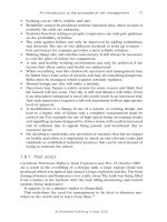
7.8.1 Dual pressure relief valves
As previously discussed, the reliability of pressure relief valves (PRVs)
depends on the time interval between testing. In some critical situations,
on continuous process operations, dual pressure relief valves are installed
Safety issues in planning a new facility 161
© Woodhead Publishing Limited, 2010
(Fig. 7.1). The advantage is that relief valves can be removed for testing
without stopping operations. The disadvantage is that this can in itself pose
a hazard to safety. Examination of the procedure needed to change a PRV
shows how mistakes can be made.
Possible errors (Fig. 7.1):
1. Close valve 1 before opening valve 2: the vessel will be without a PRV
while valve 2 is closed.
2. Close valve 1 and forget to open valve 2: the vessel has no PRV.
3. Open valve 2 and forget to close valve 1: a possible fatal injury in
attempting to remove PRV 1.
Normal operation:
• PRV 1 in operation;
• valve 1 is normally open, with vent valve shut;
• valve 2 is normally shut, with vent valve open;
• PRV 2 has been removed, tested and reinstalled.
Changeover operation:
1. PRV 1 is in operation;
2. valve 1 is open, with vent valve shut;
3. open valve 2 and close its vent valve;
4. PRV 2 is in operation;
5. close valve 1 and open its vent valve and remove PRV 1 for testing.
It can be seen that in improving reliability, hazards to safety have been
introduced. Engineering changes are needed. One provision is by the appli-
cation of a mechanical interlock system that depends on a series of trapped
keys. The fi rst key is held in the safety offi ce. When a permit is issued to
change over, the key is handed over to the technician. This key enables the
Valve 2
PRV 2
Valve 1
Pressure vessel
PRV 1
7.1 Dual pressure relief valve installation.