Báo cáo sinh học: " Research Article Algorithms for Optimally Arranging Multicore Memory Structures" docx
Bạn đang xem bản rút gọn của tài liệu. Xem và tải ngay bản đầy đủ của tài liệu tại đây (1.08 MB, 16 trang )
Hindawi Publishing Corporation
EURASIP Journal on Embedded Systems
Volume 2010, Article ID 871510, 16 pages
doi:10.1155/2010/871510
Research Article
Algorithms for Optimally Arranging Multicore
Memory Structures
Wei-Che Tseng, Jingtong Hu, Qingfeng Zhuge, Yi He, and Edwin H M. Sha
Department of Computer Science, University of Texas at Dallas, Richardson, TX 75080, USA
Correspondence should be addressed to Wei-Che Tseng,
Received 31 December 2009; Accepted 6 May 2010
Academic Editor: Chun Jason Xue
Copyright © 2010 Wei-Che Tseng et al. This is an open access article distributed under the Creative Commons Attribution License,
which permits unrestricted use, distribution, and reproduction in any medium, provided the original work is properly cited.
As more processing cores are added to embedded systems processors, the relationships between cores and memories have more
influence on the energy consumption of the processor. In this paper, we conduct fundamental research to explore the effects
of memory sharing on energy in a multicore processor. We study the Memory Arrangement (MA) Problem. We prove that
the general case of MA is NP-complete. We present an optimal algorithm for solving linear MA and optimal and heuristic
algorithms for solving rectangular MA. On average, we can produce arrangements that consume 49% less energy than an all shared
memory arrangement and 14% less energy than an all private memory arrangement for randomly generated instances. For DSP
benchmarks, we can produce arrangements that, on average, consume 20% less energy than an all shared memory arrangement
and 27% less energy than an all private memory arrangement.
1. Introduction
When designing embedded systems, the application of
the system may be known and fixed at the time of the
design. This grants the designer a wealth of information
and the complex task of utilizing the information to meet
stringent requirements, including power consumption and
timing constraints. To meet timing constraints, designers
are forced to increase the number of cores, memory, or
both. However, adding more cores and memory increases the
energy consumption. As more processing cores are added to
a processor, the relationships between cores and memories
have more influence on the energy consumption of the
processor.
In this paper, we conduct fundamental research to
explore the effects of memory sharing on energy in a multi-
core processor. We consider a multi-core system where each
core may either have a private memory or share a memory
with other cores. The Memory Arrangement Problem (MA)
decides whether cores will have a private memory or share
a memory with adjacent cores to minimize the energy
consumption while meeting the timing constraint. Some
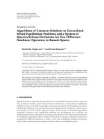
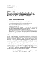
examples of memory arrangements are shown in Figure 1.
The main contributions of this paper are as follows.
(i) We prove that MA without sharing constraints is NP-
complete.
(ii) We propose an efficient optimal algorithm for solving
linear cases of MA and extend it into an efficient
heuristic for solving rectangular cases of MA.
(iii) We propose both an optimal algorithm and an
efficient heuristic for solving rectangular cases of
MA where only rectangular blocks of cores share
memories.
Our experiments show that, on average, we can produce
arrangements that consume 49% less energy than an all
shared memory arrangement and 14% less energy than an
all private memory arrangement for randomly generated
instances. For benchmarks from DSPStone [1], we can
produce arrangements that, on average, consume 20% less
energy than an all shared memory arrangement and 27% less
energy than an all private memory arrangement.
The rest of the paper is organized as follows. Related
works are presented in Section 2. Section 3 provides a
motivational example to demonstrate the importance of
MA. Section 4 formally defines MA and presents two
properties of MA. Section 5 presents an optimal algorithm
2 EURASIP Journal on Embedded Systems
v
1,1
v
1,3
v
1,2
v
2,1
v
2,3
v
2,2
(a) All Private
v
1,1
v
1,3
v
1,2
v
2,1
v
2,3
v
2,2
(b) All Shared
v
1,1
v
1,3
v
1,2
v
2,1
v
2,3
v
2,2
(c) Mixed
Figure 1: Memory arrangements. Each circle represents a core, and each rectangle represents a memory.
for linear instances of MA. Section 6 proves that MA with
arbitrary memory sharing is NP-complete. Section 7 presents
algorithms to solve rectangular instances of MA including
an optimal algorithm where only rectangular sets of cores
can share a memory and an efficient heuristic to find a
good memory arrangement in a reasonable amount of time.
Section 8 presents our experiments and the results. We
conclude our paper in Section 9.
2. Related Works
Many researchers in different areas have already begun
lowering the energy consumption of memories. On a VLIW
architecture, Zhao et al. [2] study the effect of register
file repartitioning on energy consumption. Wang et al. [3]
develop a leakage-aware modulo scheduling algorithm to
achieve leakage energy savings for DSP applications with
loops. For multiprocessor embedded systems, Qiu et al. [4]
take advantage of Dynamic Voltage Scaling to optimally
minimize the expected total energy consumption while
satisfying a timing constraint with a guaranteed confidence
probability. On a multi-core architecture, Hua et al. [5]use
Adaptive Body Biasing as well as Dynamic Voltage Scaling
to minimize both dynamic and leakage energy consumption
for applications with loops. Saha et al. [6] attack the
synchronization problems of concurrent memory accesses by
proposing a new software transactional memory system that
makesitbotheasyandefficient for multiprocess programs
to share memory. Kumar et al. [7] focus on the interconnects
of a multi-core processor. They show that interconnects play
a bigger role in a multi-core processor than in a single core
processor. We attack the problem from a different angle,
exploring how memory sharing in a multi-core processor can
affect the energy consumption.
Other researchers have worked on problems more
specific to the memory subsystem of multi-core systems
including data partitioning and task scheduling. In a timing
focused work, Xue et al. [8] present a loop scheduling
with memory management technique to completely hide
memory latencies for applications with multidimensional
loops. Suhendra et al. [9] present an ILP formulation that
performs data partitioning and task scheduling simultane-
ously. Zhang et al. [10] present two heuristics to solve larger
problems efficiently. The memory architectural model used
is a virtually shared scratch pad memory (VS-SPM) [11],
where each core has its own private memory and treats all
the memories of the other cores as one big shared memory.
Other researchers also start with a given multi-core memory
architecture and use the memory architecture to partition
data [12–16]. We approach the problem by designing the
memory architecture around the application.
A few others have taken a similar approach. Meftali
et al. [17] provide a general model for distributing data
between private memories and a global shared memory.
They assume that each processor has a local memory, and
all processors share a remote memory. This is similar to
an architecture with private L1 memories and a shared L2
memory. This architecture does not provide the possibility of
only a few processors sharing a memory. The integer linear
programming-(ILP-) based algorithm presented decides on
the size of the private memories. Ozturk et al. [18] also com-
bine both memory hierarchy design and data partitioning
with an ILP approach to minimize the energy spent on data
access. The weaknesses of this approach are that ILP takes
an unreasonable amount of time for large instances, and
timing is not considered. The generated architecture might
be energy efficient but takes a long time to complete the
tasks. In another publication, Ozturk et al. [19] aim to lower
power consumption by providing a method for partitioning
the available memory to the processing units or groups of
processing units based on the number of accesses on each
data element. The proposed method does not consider any
issues related to time such as the time it takes to access the
data or the duration of the tasks on each processing unit. Our
proposed algorithms will consider these time constraints to
ensure that the task lengths do not grow out of hand.
3. Motivational Example
In this section, we present an example that illustrates the
memory arrangement problem. We informally explain the
problem while we present the example.
The cores in a multi-core processor can be arranged
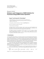
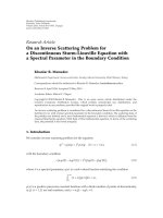
either as a line or as a rectangle. For our example, we have
6 cores arranged in a 2
×3 rectangle as shown in Figure 2.
Each core has a number of operations that it must
complete. We can divide these operations into those that
require memory accesses and those that do not. The com-
putational time and energy required by operations that do
not require memory accesses are independent of the memory
EURASIP Journal on Embedded Systems 3
v
1,1
v
1,3
v
1,2
v
2,1
v
2,3
v
2,2
Figure 2: Motivational example. Each circle denotes a core.
Table 1: Data accesses.
v
1,1
v
1,2
v
1,3
v
2,1
v
2,2
v
2,3
v
1,1
500300
v
1,2
000005
v
1,3
002000
v
2,1
400000
v
2,2
000020
v
2,3
050000
arrangement. We do not consider the energy required by
these operations since they are all constants, but we do
consider the time required since it may affect the ability of
a core to meet its timing constraint. Each core then has a
constant time for the operations that do not require memory
accesses. For our example, each core requires ten units of
time for these operations.
For the operations that do require memory accesses, we
count the number of these operations for each pair of cores.
This number is the number of times a core needs to access
the memory of another core. These counts for our example
are shown in Ta bl e 1 .InTa bl e 1 , the left column shows
which core requires the memory accesses. The top row shows
which core the memory accessed belongs to. For instance,
v
1,1
has five operations that access its own memory and three
operations that access the memory of v
2,1
.
The computational time and energy required by each of
these memory-access operations dependent on the memory
arrangement. The least amount of time and energy required
is when a core with private memory accesses its own memory.
For our example, each of these accesses takes one unit of
time and one unit of energy. The most amount of time and
energy required is when a core accesses a remote memory.
For our example, each of these accesses takes three units of
time and three units of energy. In between, the amount of
time and energy required when a core accesses a memory that
it shares with another core is two units of time and two units
of energy.
To make sure that the computations do not take too
long, we restrict the time that each core is allowed to
take. If, for a memory arrangement, any core takes more
time than the timing constraint allows, we say that the
memory arrangement does not meet the timing constraint.
Sometimes it is impossible to find a memory arrangement
that meets the timing constraint. For our example, the timing
constraint is 25 units of time.
Two simple memory arrangements are the all private
memory arrangement and the all shared memory arrange-
ment. These are shown in Figure 1. Figure 1(a) shows the
all private memory arrangement where each core has its
own memory. Figure 1(b) shows the all shared memory
arrangement where all cores share one memory.
Let us calculate the time and energy used by these two
memory arrangements. First, let us consider the cores v
1,1
and v
2,1
. In the all private memory arrangement, v
1,1
uses
5 units of time and energy to access its own memory and
9 units of time and energy to access the memory of v
2,1
.
Including the operations that do not need memory accesses,
v
1,1
uses a total of 24 units of time and 14 units of energy.
v
2,1
uses 12 units of time and energy to access the memory of
v
1,1
. Including the non-memory-access operations, v
2,1
uses
a total of 22 units of time and 12 units of energy. Together,
these two cores use 26 units of energy.
In the all shared memory arrangement, v
2,1
uses 8 units
of time and energy to access the memory of v
1,1
. Including
the non-memory-access operations, v
2,1
uses a total of 18
units of time and 8 units of energy. v
1,1
uses 10 units of time
and energy to access its own memory and 6 units of time
and energy to access the memory of v
2,1
. Including the non-
memory-access operations, v
1,1
uses a total of 26 units of time
and 16 units of energy. Together, these two cores use 24 units
of energy, which is less than the 26 units of energy that the
all private memory arrangement uses. However, v
1,1
takes 26
units of time, thus the all shared memory arrangement does
not meet the timing constraint. We should use the all private
memory arrangement even though it uses more energy.
Let us now consider the cores v
1,2
, v
1,3
, v
2,2
,andv
2,3
.
In the all private memory arrangement, cores v
1,2
and v
2,3
each use 15 units of time and energy to access each other’s
memory. Including the non-memory-access operations, v
1,2
and v
2,3
each use 25 units of time and 15 units of energy.
v
1,3
and v
2,2
each use 2 units of time and energy to access its
own memory. Including the non-memory-access operations,
v
1,3
and v
2,2
each use 12 units of time and 2 units of energy.
Together, these four cores use 34 units of energy.
In the all shared memory arrangement, cores v
1,2
and v
2,3
each use 10 units of time and energy to access each other’s
memory. Including the non-memory-access operations, v
1,2
and v
2,3
each use 20 units of time and 10 units of energy.
v
1,3
and v
2,2
each use 4 units of time and energy to access its
own memory. Including the non-memory-access operations,
v
1,3
and v
2,2
each use 14 units of time and 4 units of energy.
Together, these four cores use 28 units of energy, which is
less than the 34 units of energy that the all private memory
arrangement uses, but the all shared memory arrangement
does not meet the timing constraint for v
1,1
. Hence, the best
we can do with either an all shared or all private memory
arrangement is to use 60 units of energy.
Instead of an all private or all shared memory arrange-
ment, it would be better to have a mixed memory arrange-
ment where v
1,1
and v
2,1
each use a private memory while the
rest of the cores share one memory as shown in Figure 1(c).
This memory arrangement uses only 54 units of energy and
meets the timing constraint. All of our algorithms are able to
achieve this arrangement, but it is possible to do better.
4 EURASIP Journal on Embedded Systems
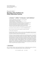
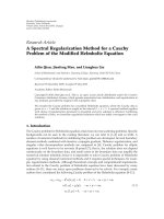
Figure 3: Linear array of cores. Each circle denotes a core.
v
1
v
2
v
3
v
4
v
5
v
6
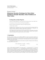
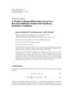
Figure 4: Memory sharing example. Each circle represents a single
core. All cores in the same rectangle share a memory.
If we have an arrangement such that v
1,2
and v
2,3
share a
memory but all the other cores have private memories, then
we can meet the timing constraint and use only 50 units of
energy. This arrangement, however, is difficult to implement
since v
1,2
and v
2,3
are not adjacent to each other. In a larger
chip, it is not advantageous from an implementation point of
view to have two cores on opposite sides of the chip share a
memory. Moreover, we prove that this version of the problem
is NP-complete in Section 6.
4. Problem Definition
We now formally define our problem. Let us consider the
problem of memory sharing to minimize energy while
meeting a timing constraint assuming that all operations and
data have already been assigned to cores. We call this problem
the Memory Arrangement Problem (MA). We first explain
the memory architecture then MA.
We ar e give n a seq ue nc e V
=v
1
, v
2
, v
3
, ,v
n
of
processor cores. The cores are arranged either in a line
or a rectangle. For example, the cores in Section 5 are
arranged in a line. An example is shown in Figure 3.Each
core has operations and data assigned to it. We can divide
the operations into memory-access-operations and non-
memory-access operations. For a core u
∈ V , b(u) is the
time it takes for u to complete all its non-memory access
operations. For cores u, v
∈ V, w(u, v) is the number of times
core u accesses a data that belongs to v. The time and energy
it takes for u to access a data that belongs to v depends on
how the memories of u and v are related. If u and v share
the same private memory, that is, u
= v,andu does not
share a memory with any other cores, then the time and
energy each memory-access operation takes are t
0
and e
0
,
respectively. If u and v share a memory, but u
/
=v, then the
time and energy each memory-access operation takes are t
1
and e
1
,respectively.Ifu and v do not share a memory, then
the time and energy each memory-access operation takes are
t
2
and e
2
, respectively. For convenience, let us denote the time
and energy each memory-access operation takes as C
t
(u, v)
and C
e
(u, v), respectively. For example, if v
3
and v
5
share the
same memory, then C
t
(v
3
, v
5
) = t
1
and C
e
(v
3
, v
5
) = e
1
.
We can represent the memory sharing of the cores with
a partition of the cores such that two cores are in the same
block if they share a memory. Let us consider the example
in Figure 4. The memory sharing can be captured by the
partition
{{v
1
, v
2
, v
3
}, {v
4
}, {v
5
, v
6
}}.
We wish to find a partition of the cores to minimize the
total energy used by memory-access operations:
u∈V
v∈V
C
e
(
u, v
)
w
(
u, v
)
.
(1)
Energy is not our only concern. We also want to make
sure that all operations finish within the timing constraint.
Aside from memory-access operations, non-memory-access
operations also take time. Since the memory sharing does not
effect the time taken by non-memory access operations, for
each u
∈ V we describe all the time taken by non-memory-
access operations by a single number b(u). To meet a timing
constraint q,
b
(
u
)
+
v∈V
C
t
(
u, v
)
w
(
u, v
)
≤ q ∀u ∈ V.
(2)
MA then asks, given a sequence V, w(u, v)
∈ Z
∗
for each
u, v
∈ V, b(u) ∈ Z
∗
for each u ∈ V, and nonnegative
integers t
0
, e
0
, t
1
, e
1
, t
2
, e
2
, q, “what is a partition P such
that the total energy used by memory-access operations is
minimized and the timing constraint is met?”
Now that we have formally defined MA, we look at two
of its properties. We use these properties in the later sections.
4.1. Optimal Substructure Property. Suppose that P is an
optimal partition of V for an instance I
=V, w, b,
t
0
, e
0
, t
1
, e
1
, t
2
, e
2
, q.LetB
1
be the block that contains v
1
.
Suppose that P
is an optimal partition for the subinstance
I
=V
, w, b
, t
0
, e
0
, t
1
, e
1
, t
2
, e
2
, q,whereV
and b
are
defined as follows:
V
= V −B
1
b
(
u
)
= b
(
u
)
+ t
2
v∈B
1
w
(
u, v
)
∀u ∈ V
.
(3)
Lemma 1. P
= P −{B
1
} is an optimal partition for I
.
Proof. Let us prove Lemma 1 by contradiction. Suppose for
the purpose of contradiction that P
is not an optimal parti-
tion for I
. Then there is a partition Q
for I
such that Q
is a
better partition than P
. Since Q
is a partition that meets the
timing requirements in I
, Q = Q
∪{B
1
} is also a partition
that meets the timing requirements in I. Furthermore, Q is a
better partition than P, a contradiction.
4.2. Conglomerate Property. Suppose a partition P contains
two different blocks of size at least 2, that is, B
i
, B
j
∈ P,where
i
/
= j, |B
i
| > 1, and |B
j
| > 1. Let P
= P −{B
i
, B
j
}∪{B
i
∪B
j
}.
If t
1
≤ t
2
and e
1
≤ e
2
, then P
would be a partition that is as
good as or better than P.
EURASIP Journal on Embedded Systems 5
Figure 5: Subinstances. There are 6 sets cores. Each set has one
more core than the previous set.
Proof. Let V
= V − B
1
− B
2
and B
= B
1
∪ B
2
. The total
energy used by the cores in B
1
and B
2
is
u∈B
1
v∈B
1
e
1
w
(
u, v
)
+
u∈B
1
v∈V −B
1
e
2
w
(
u, v
)
+
u∈B
2
v∈B
2
e
1
w
(
u, v
)
+
u∈B
2
v∈V −B
2
e
2
w
(
u, v
)
=
u∈B
1
v∈B
1
e
1
w
(
u, v
)
+
u∈B
1
v∈B
2
e
2
w
(
u, v
)
+
u∈B
1
v∈V −B
e
2
w
(
u, v
)
+
u∈B
2
v∈B
1
e
2
w
(
u, v
)
+
u∈B
2
v∈B
2
e
1
w
(
u, v
)
+
u∈B
2
v∈V −B
e
2
w
(
u, v
)
≥
u∈B
1
v∈B
1
e
1
w
(
u, v
)
+
u∈B
1
v∈B
2
e
1
w
(
u, v
)
+
u∈B
1
v∈V −B
e
2
w
(
u, v
)
+
u∈B
2
v∈B
1
e
1
w
(
u, v
)
+
u∈B
2
v∈B
2
e
1
w
(
u, v
)
+
u∈B
2
v∈V −B
e
2
w
(
u, v
)
=
u∈B
v∈B
e
1
w
(
u, v
)
+
u∈B
v∈V −B
e
2
w
(
u, v
)
.
(4)
5. Linear Instances
In this section, we consider the linear instances of MA. Linear
instances are where the cores are arranged in a line. An
example is shown in Figure 3. Let us make the assumption
that only cores next to each other can share a memory. In
other words, shared memories must only contain continuous
blocks of cores, that is, if u
i
, u
j
∈ V are in the same block
B
x
∈ P, then u
k
∈ B
x
for all i ≤ k ≤ j. This is the case in
real applications since it is difficult to share memory between
cores that are not adjacent. We consider what happens when
we allow arbitrary cores to share a memory in Section 6.
Using the optimal substructure property of MA, we can
solve the problem recursively. Unfortunately, in Section 4.1
we assumed that we already know the first block of an
optimal partition. Since we do not know any optimal
partitions, we will try all the possible first blocks and
then find the best block. Figure 5 shows an example of
the sub-instances of a problem. Notice that because of our
assumption, all the sub-instances include v
n
.
Let the largest sub-instance that contains the core v
i
be I
i
=V
i
, w, b
i
, t
0
, e
0
, t
1
, e
1
, t
2
, e
2
, q,whereV
i
and b
i
are
Input: An instance I of Linear MA.
Output: An optimal partition P
1
and its energy
consumption d
1
.
(1) d
n+1
← 0
(2) P
n+1
←{}
(3) for i ← n to 1 do
(4) V
i
←{v
i
, v
i+1
, v
i+2
, , v
n
}
(5) d
i
←∞
(6) P
i
←{}
(7) for ← 1ton −i +1 do
(8) V
i
←{v
i
, v
i+1
, v
i+2
, , v
i+−1
}
(9) Compute c
i
and d
i
.
(10) if d
i
<d
i
then
(11) d
i
← d
i
(12) P
i
←{V
i
}∪P
i+
(13) end if
(14) end for
(15) end for
Algorithm 1: Optimal linear memory arrangement (OLMA).
defined as follows:
V
i
={v
i
, v
i+1
, v
i+2
, ,v
n
},
b
i
(
u
)
= b
(
u
)
+ t
2
v∈V −V
i
w
(
u, v
)
∀u ∈ V
i
.
(5)
Note that I
1
= I, and there are, including I
1
,onlyn sub-
instances.
For each sub-instance I
i
,letP
i
be an optimal partition
that satisfies the timing constraints. Let d
i
be the energy
consumption of P
i
or ∞ if no partition can meet the timing
constraint for I
i
.LetV
i
be the first cores in V
i
, that
is, V
i
={v
i
, v
i+1
, v
i+2
, ,v
i+−1
}.Letc
i
be the minimum
energy necessary for I
i
if V
i
is a block in P
i
.Letd
i
be ∞ if
no partition of V
i
that contains V
i
as a block satisfies the
timing constraints. Otherwise, let d
i
be c
i
.Wecandefinec
i
,
d
i
,andd
i
recursively as (6), (7), and (8), respectively.
During the computation of d
i
, we record the optimal
value of by recording the corresponding partition in P
i
.
Let P
n+1
={}.Forall1 ≤ i ≤ n,letk be an optimal
value of used to compute d
i
. Then P
i
={V
k
i
}∪P
i+k
.If
d
i
=∞, then there is no partition for I
i
that satisfies the
timing requirement, and P
i
is undefined. P
1
is an optimal
partition for I,andd
1
is the energy necessary. If d
1
=∞, then
there does not exist a partition for I that satisfies the timing
requirement.
Optimal Linear Memory Arrangement (OLMA), shown
in Algorithm 1, is an algorithm to compute P
i
and d
i
. It starts
by setting the sentinels for P
n+1
and d
n+1
in lines 1-2. The
body of the algorithm is the for loop on lines 3–15. Notice
that it computes P and d from n to 1. For each value of
i,OLMAcomputesd
i
starting from = 1. c
i
and d
i
are
computed according to equations (6)and(7) on line 9. Lines
10–13 record the optimal P
i
whenever a better d
i
is found. At
the end of the algorithm, P
1
holds an optimal partition for
6 EURASIP Journal on Embedded Systems
v
1
v
2
v
3
v
4
v
5
v
6
Figure 6: Example for OLMA. Each circle is a core.
Table 2: Data accesses.
v
1
v
2
v
3
v
4
v
5
v
6
v
1
500003
v
2
000500
v
3
002000
v
4
050000
v
5
000020
v
6
400000
I,andd
1
holds the energy consumption of P
1
. The running
time of OLMA is O(n
4
)wheren is the number of cores.
LetusillustrateOLMAwithanexample.Weunrollthe
example from Section 3 to create a linear example of 6 cores
as shown in Figure 6. In other words, V
=v
1
, v
2
, v
3
, ,v
6
.
The memory access operations are shown in Ta b le 2 .Foreach
core v
∈ V, b(u) = 10. t
0
= e
0
= 1, t
1
= e
1
= 2, and
t
2
= e
2
= 3. The timing constraint q = 25.
The computed values of d
i
are shown in Ta bl e 3 , and the
computed values of d
i
and P
i
are shown in Ta bl e 4 .From
these values, we see that if v
1
is not in a block by itself, then
it is unable to meet the timing constraint. Thus, d
1
=∞
for >1. The optimal partition for this example is P
1
=
{{
v
1
}, {v
2
, v
3
, v
4
}, {v
5
}, {v
6
}}, and its energy consumption is
d
1
= 52. Consider the following:
c
i
=
⎧
⎪
⎪
⎪
⎪
⎨
⎪
⎪
⎪
⎪
⎩
d
i+
+
u∈V
i
v∈V
i
e
0
w
(
u, v
)
+
u∈V
i
v∈V −V
i
e
2
w
(
u, v
)
if
V
i
=
1,
d
i+
+
u∈V
i
v∈V
i
e
1
w
(
u, v
)
+
u∈V
i
v∈V −V
i
e
2
w
(
u, v
)
if
V
i
> 1,
(6)
d
i
=
⎧
⎪
⎪
⎪
⎪
⎪
⎪
⎪
⎨
⎪
⎪
⎪
⎪
⎪
⎪
⎪
⎩
∞
if
V
i
=
1andb
i
(
u
)
+ t
0
w
(
u, v
)
+
v∈V
i
−V
i
t
2
w
(
u, v
)
>qfor any u ∈ V
i
,
∞ if
V
i
> 1andb
i
(
u
)
+ t
1
w
(
u, v
)
+
v∈V
i
−V
i
t
2
w
(
u, v
)
>qfor any u ∈ V
i
,
c
i
otherwise,
(7)
d
i
=
⎧
⎪
⎨
⎪
⎩
0ifi = n +1,
min
1≤≤n−i+1
d
i
otherwise.
(8)
6. NP-Completeness
LetusconsiderMAifwedonotassumethatonlycoresnext
to each other may share a memory. Since any cores can share
a memory, the shape that the cores are arranged in does not
affect the solution. We first define the decision version of MA
and then show that it is NP-complete.
An instance of MA consists of a set V , functions w : V
×
V → N and b : V → N, nonnegative integers t
0
, e
0
, t
1
, e
1
,
t
2
, e
2
, q,andk. The question is as follows. Is there a partition
P of V such that the timing requirement q is met and the
energy consumption is less than k?
Let us apply the conglomerate property. For any partition
P, there is a partition P
such that P
is at least as good
as P and P
contains only one block that has a cardinality
greater than 1. We can specify P
with a subset V
⊆ V
where V
contains the cores that do not share a memory with
another core. Conversely, for any subset V
⊆ V , there exists
a corresponding partition P
={V − V
}∪{{v}|v ∈ V
}.
Thus, we can restate the decision question as follows. Is there
a subset V
⊆ V such that its corresponding partition meets
the timing and energy requirements?
Theorem 1. MA is NP-complete.
Proof. It is easy to see that MA
∈NP since a nondeterministic
algorithm needs only to guess a partition of V and check in
polynomial time whether that partition meets the timing and
energy requirements.
We transform the well-known NP-complete problem
KNAPSACK to MA. First, let us define KNAPSACK. An
instance of KNAPSACK consists of a set U,asizes(u)
∈ Z
+
and a value v(u) ∈ Z
+
for each u ∈ U, and positive integers
B and K. The question is as follows. Is there a subset U
⊆ U
such that
u∈U
s(u) ≤ B and
u∈U
v(u) ≤ K?
Let U
= u
1
, u
2
, u
3
, ,u
n
, s(u), v(u), B,andK be
any instances of KNAPSACK. We must construct set V,a
functions w : V
×V → N and b : V → N, and nonnegative
integers t
0
, e
0
, t
1
, e
1
, t
2
, e
2
, q,andk such that there is a subset
U
⊆ U such that
u∈U
s(u) ≤ B and
u∈U
v(u) ≤ K if and
EURASIP Journal on Embedded Systems 7
only if there is a subset V
⊆ V such that its corresponding
partition meets both the timing and energy requirements.
We construct a special case of MA such that the resulting
problem is the same as KNAPSACK. We start by setting V
=
U ∪{u
0
}.Then,forallv
1
, v
2
∈ V,
w
(
v
1
, v
2
)
=
⎧
⎪
⎪
⎪
⎪
⎨
⎪
⎪
⎪
⎪
⎩
s
(
v
2
)
if v
1
= u
0
and v
2
∈ U,
s
(
v
2
)
+ v
(
v
2
)
if v
1
= v
2
and v
1
∈ U,
0 otherwise.
(9)
For all v
∈ V,
b
(
v
)
=
⎧
⎪
⎪
⎨
⎪
⎪
⎩
0ifv ∈ U,
u∈U
v
(
u
)
if v = u
0
.
(10)
We complete the construction of our instance of MA by
setting t
0
= 0, e
0
= 1, t
1
= 1, e
1
= 2, t
2
= 2, e
2
= 3, q =
u∈U
[s(u)+v(u)] + B,andk =
u∈U
[4s(u)+2v(u)] −K.
It is easy to see how the construction can be accomplished
in polynomial time. All that remains to be shown is that the
answer to KNAPSACK is yes if and only if the answer to MA
is yes.
Since w(u
0
, u
0
) = 0, it is of no advantage for u
0
to be in
a block by itself. Therefore, u
0
/
∈V
unless V ⊆ V
.Thetime
that u
0
needs to finish its tasks is
b
(
u
0
)
+
v∈V
C
t
(
u
0
, v
)
w
(
u
0
, v
)
=
u∈U
v
(
u
)
+
u∈U−S
s
(
u
)
+
u∈S−{u
0
}
2s
(
u
)
=
u∈U
[
s
(
u
)
+ v
(
u
)
]
+
u∈S−{u
0
}
s
(
u
)
.
(11)
Notice that the time required by u
0
is greater than any
u
∈ U. Hence, the timing constraint is met if and only if
u∈U
[
s
(
u
)
+ v
(
u
)
]
+
u∈S−{u
0
}
s
(
u
)
≤ q =
u∈U
[
s
(
u
)
+ v
(
u
)
]
+ B.
(12)
Thus,
u∈V
−{u
0
}
s
(
u
)
≤ B.
(13)
Table 3: d
i
.
123456
i
152
∞∞∞∞∞
24648384040
331333535
4293131
51416
612
Table 4: d
i
and P
i
.
id
i
P
i
152 {{v
1
}, {v
2
, v
3
, v
4
}, {v
5
}, {v
6
}}
238 {{v
2
, v
3
, v
4
}, {v
5
}, {v
6
}}
331 {{v
3
}, {v
4
}, {v
5
}, {v
6
}}
429 {{v
4
}, {v
5
}, {v
6
}}
514 {{v
5
}, {v
6
}}
612 {{v
6
}}
70 {}
The total energy consumed is
u∈V
v∈V
C
e
(
u, v
)
w
(
u, v
)
=
v∈U
C
e
(
u
0
, v
)
w
(
u
0
, v
)
+
u∈U
C
e
(
u, u
)
w
(
u, u
)
=
u∈U−V
2s
(
u
)
+
u∈V
−{u
0
}
3s
(
u
)
+
u∈U−V
2
[
s
(
u
)
+ v
(
u
)
]
+
u∈V
−{u
0
}
[
s
(
u
)
+ v
(
u
)
]
=
u∈U
[
4s
(
u
)
+2v
(
u
)
]
−
u∈V
−{u
0
}
v
(
u
)
.
(14)
The energy consumption constraint is met if and only if
u∈U
[
4s
(
u
)
+2v
(
u
)
]
−
u∈V
−{u
0
}
v
(
u
)
≤
u∈U
[
4s
(
u
)
+2v
(
u
)
]
−K.
(15)
Thus,
u∈V
−{u
0
}
v
(
u
)
≤ K.
(16)
Hence, there is a subset V
⊆ V that meets both the timing
and energy requirements if and only if there is a subset U
⊆
U such that
u∈U
s(u) ≤ B and
u∈U
v(u) ≤ K.Thus,MA
is NP-complete.
7. Rectangular Instances
Since general MA is NP-complete and linear MA is in P, let us
consider the case when the cores are arranged as a rectangle.
8 EURASIP Journal on Embedded Systems
An example of such an arrangement is our motivational
example shown in Figure 2. We extend OLMA to solve the
rectangular case in Section 7.1.InSection 7.2,wedefine
what staircase-shaped sets are. Then we use staircase-shaped
sets to optimally solve rectangular MA in Section 7.3.We
finally present a good heuristic to solve rectangular MA in
Section 7.4.
7.1. Zigzag Rectangular Partitions. We propose an algorithm
Zigzag Rectangular Memory Arrangement (ZiRMA) to solve
this problem. ZiRMA transforms rectangular instances into
linear instances before applying OLMA. It runs in polyno-
mial time but cannot guarantee optimality.
Let us use OLMA to handle this case by treating the
rectangle as a zigzag line as shown in Figure 7(b).To
transform an m
×n rectangle into a line, we can simply relabel
each core v
i,j
of an m × n rectangle as v
n·i+j
. An example of a
resulting line is shown in Figure 7(a).Noticehowv
1,5
and v
2,1
are not adjacent in the rectangle, but they are adjacent in the
line. Instead, let us relabel the cores with a continuous zigzag
line so that each core v
i,j
of an m ×n rectangle becomes
v
j(−1)
i+1
+(n+1)[(i+1) mod 2]+n(i−1).
(17)
The resulting line on the same rectangle is shown in
Figure 7(b). Notice how adjacent cores in the line are also
adjacentintherectangle.NowwecanuseOLMAtosolvethe
linear problem.
Unfortunately, not all cores adjacent in the rectangle are
adjacent in the line. For example, v
1,2
and v
2,1
are adjacent in
the rectangle, but they are separated by 6 other cores in the
line. To mitigate this problem, we run OLMA twice—once
on the horizontal zigzag line shown in Figure 7(b) and once
on the vertical zigzag line shown in Figure 7(c). This time, let
us relabel the cores in a vertical zigzag manner so that each
core v
i,j
of an m ×n rectangle becomes
v
i(−1)
j+1
+(m+1)[(j+1) mod 2]+m(j−1).
(18)
After both iterations are complete, we have two partitions
P
h
and P
v
of the same set of cores. We construct a new
partition such that two cores share a memory if they share
a memory in either P
h
or P
v
. To create the final partition, we
merge a block from P
h
and a block from P
v
if they share a
core. An example merge is shown in Figure 8.
ZiRMA is summarized in Algorithm 2. Its running time
is O(m
4
n
4
)foranm × n rectangle. We illustrate ZiRMA
with our motivational example. We transform the cores
according to Tab le 5 . The accesses for the horizontal zigzag
transformation are shown in Ta b le 2 , and the accesses for
the vertical zigzag transformation are shown in Ta bl e 6.
The resulting partitions are shown in Figure 9. In this case,
the reverse transformations of P
h
and P
v
are the same, so
merging does not have an effect.
As we can see from Figure 8, the shapes created by this
algorithm may be long and winding, unsuitable for real
implementations. Next, we make the restriction that the
cores sharing a memory must be of a rectangular shape.
To optimally solve this problem, we introduce the concept
staircase-shaped set of cores.
Table 5: Core transformations.
Rectangular Horizontal zigzag Vertical zigzag
v
1,1
v
1
v
1
v
1,2
v
2
v
4
v
1,3
v
3
v
5
v
2,1
v
6
v
2
v
2,2
v
5
v
3
v
2,3
v
4
v
6
Table 6: Accesses for vertical transformation.
v
1
v
2
v
3
v
4
v
5
v
6
v
1
530000
v
2
400000
v
3
002000
v
4
000005
v
5
000020
v
6
000500
7.2. Staircase-Shaped Sets. Letuscallasetofcores
V
s
staircase shaped if V
s
satisfies the following requirements.
(1) All cores are right-aligned, that is, for each 1
≤ i ≤ m,
there is an integer s
i
such that v
i,j
/
∈V
s
for all 1 ≤ j ≤
s
i
and v
i,j
∈ V
s
for all s
i
<j≤ n.
(2) Each row has at least as many cores in V
s
as the
previous row, that is, s
1
≥ s
2
≥ s
3
≥···≥s
m
.
Some examples of staircase-shaped sets are shown in
Figure 10.
We can uniquely identify any staircase-shaped sub-
set V
s
of a rectangular set V by an m-tuple s =
(s[1], s[2],s[3], , s[m]) such that s[i] is the number of cores
from row i of V that are not in V
s
. For example, the tuples
corresponding to the sets in Figures 10(a), 10(b), 10(c),and
10(d) are (2, 1,0), (2, 2, 0), (4, 2, 1), and (4,4, 2), respectively.
Let us consider all rectangular subsets V
i,j
s
of any
staircase-shaped set V
s
such that V
s
− V
i,j
s
is a staircase-
shaped set. Let V
i,j
s
={v
i
,j
| i
≤ i, j
≤ j,andv
i
,j
∈ V
s
}.
It is easy to see that V
s
i,j
= V
s
− V
i,j
s
is a staircase-shaped
subset of V
s
if V
s
is a staircase-shaped set, 0 ≤ i ≤ m,and
0
≤ j ≤ n. We see that s
i,j
is an m-tuple where s
i,j
[k] =
max(s[k], j)ifk ≤ i and s
i,j
[k] = s[k]ifk>i.
Unfortunately, V
i,j
s
as defined does not necessarily have
to be rectangular. To restrict V
i,j
s
to be rectangular, we define
an m-tuple k
s
such that for all 1 ≤ i ≤ m, k
s
[i] is the largest
integer such that k
s
[i] <iand s[k
s
[i]]
/
=s[i]. As a sentinel, let
s[0]
= n+1 so that s[0]
/
=s[i]forall1≤ i ≤ m.Inwords,row
k
s
[i] is the closest row before row i that is different from row i.
For example, the k
s
’s corresponding to Figures 10(a), 10(b),
10(c),and10(d) are (0, 1,2), (0, 0, 2), (0, 1, 2), and (0, 0,2),
respectively. Then, for all i, j such that 1
≤ i ≤ m, j ≤ n,and
s[i] <j
≤ min(s[k
s
[i]], n), V
i,j
s
is rectangular.
EURASIP Journal on Embedded Systems 9
(a) Discontinuous (b) Horizontal (c) Vertical
Figure 7: Zigzag lines. We transform a rectangular problem into a linear problem by following one of these zigzag lines.
(a) P
h
(b) P
v
(c) P
Figure 8: Merging P
h
and P
v
. P is the partition resulting from merging P
h
and P
v
.
Input: An instance I of rectangular MA.
Output: A partition P and its energy consumption d.
(1) Create a linear instance I
h
from I by transforming each
core v
i,j
according to (17).
(2) Find the optimal partition P
h
of I
h
with OLMA.
(3) Reverse the transformation of each core in P
h
by
applying (17)inreverse.
(4) Create a linear instance I
v
from I by transforming each
core v
i,j
according to equation (18).
(5) Find the optimal partition P
v
of I
v
with OLMA.
(6) Reverse the transformation of each core in P
v
by
applying (18)inreverse.
(7) Create P by merging P
h
and P
v
.
(8) Compute the energy consumption d of P.
Algorithm 2: Zigzag rectangular memory arrangement (ZiRMA).
Lemma 2. If a partition P of a nonempty staircase-shaped set
V is composed of only rectangular blocks, there exists a block
B
∈ P such that V −B is a staircase-shaped set.
Proof. Let us suppose that V is m high and n wide. V then
has at most m top left corners. For example, in Figure 10(a),
the 3 top left corners are (3, 1), (2, 2), and (1, 3). Since
all blocks of P are rectangular, none of the top left corners
are in the same block. One of the blocks containing these
corners is a block B
such that V − B
is a staircase-shaped
set. Let B
1
, B
2
, B
3
, ,B
j
,wherej ≤ m, be the sequence
of these blocks ordered by the row index of the top left
corner that it contains. Let us consider all these blocks in this
order.
If B
1
does not extend to the right underneath B
2
, then it is
a block such that the remaining blocks compose a staircase-
shaped set, and the lemma is correct. If it does not, then it is
not B
, and one of the remaining blocks must be B
.
Let us consider B
i
,wherei ≤ j. Since we are considering
B
i
, B
i−1
must not be B
,thusB
i−1
extends underneath B
i
,and
B
i
cannotextenddownnexttoB
i−1
.Thus,ifB
i
is not B
,
then it must extend to the right. If B
i
does not extend to the
right underneath B
i+1
, then it is B
, and the lemma is correct.
Otherwise, it is not B
, and we consider B
i+1
.Wecontinue
this until we come to B
j
.
By the same argument, B
j
doesnotextenddownnextto
B
j−1
. Since this is the topmost top left corner, there is nothing
above this block. Thus, B
j
is B
. Thus, we have found a block
such that the remaining blocks compose a staircase-shaped
set.
Lemma 3. If a partition of a rectangular set is composed of
only k rectangular blocks, there exists a sequence of the block
B
1
, B
2
, B
3
, ,B
k
such that for any integer 1 ≤ i ≤ k,
k
j
=i
B
j
is staircaseshaped.
Proof. Since a rectangular set is staircase-shaped, we can
repeatedly apply Lemma 2 to find such a sequence.
7.3. Staircase Rectangular Partitions. We use staircase-shaped
sets to find the optimal partition of a rectangular set of
cores that only has rectangular blocks. For an MA instance
10 EURASIP Journal on Embedded Systems
Table 7: d
s
and P
s
.
s Shape d
s
P
s
(4, 3, 3) 0 {}
(4, 3, 2) 15 {{v
2,3
}}
(4, 3, 1) 17 {{v
2,2
}, {v
2,3
}}
(4, 3, 0) 29 {{v
2,1
}, {v
2,2
}, {v
2,3
}}
(4, 2, 2) 17 {{v
1,3
}, {v
2,3
}}
(4, 2, 1) 19 {{v
1,3
}, {v
2,2
}, {v
2,3
}}
(4, 2, 0) 31 {{v
1,3
}, {v
2,1
}, {v
2,2
}, {v
2,3
}}
(4, 1, 1) 28 {{v
1,2
, v
1,3
, v
2,2
, v
2,3
}}
(4, 1, 0) 40 {{v
2,1
}, {v
1,2
, v
1,3
, v
2,2
, v
2,3
}}
(4, 0, 0) 54 {{v
1,1
}, {v
2,1
}, {v
1,2
, v
1,3
, v
2,2
, v
2,3
}}
I =V, w, t
0
, e
0
, t
1
, e
1
, t
2
, e
2
, b, q,letI
s
be the sub-instance
that contains a staircase-shaped set V
s
⊆ V,wheres is an
m + 1-tuple such that s[0]
= n + 1 and for all 1 ≤ i ≤ m,
0
≤ s[i] ≤ n and s[1] ≥ s[2] ≥ s[3] ≥ ··· ≥ s[m]. I
s
=
V
s
, w, t
0
, e
0
, t
1
, e
1
, t
2
, e
2
, b
s
, q,whereV
s
and b
s
are defined as
follows:
V
s
=
v
i,j
| 1 ≤ i ≤ m and s
[
i
]
<j≤ n
,
b
s
(
u
)
= b
(
u
)
+ t
2
v∈V −V
s
w
(
u, v
)
∀u ∈ V
s
.
(19)
Let s
0
be the m + 1-tuple that consists of all 0’s except
s
0
[0] = n +1,ands
n
be the m + 1-tuple that consists of all
n’s except s
n
[0] = n +1,i.e.s
0
= (n +1,0,0,0, ,0) and
s
n
= (n +1,n, n, n, , n). Note that I
s
0
= I.Foreachsub-
instance I
s
,letP
s
be an optimal partition that satisfies the
timing constraint. Let d
s
be the energy consumption of P
s
or
∞ if no partition for I
s
can meet the timing constraint. Let
V
i,j
s
={v
i
,j
|i
≤ i, j
≤ j,and v
i
,j
∈ V
s
}.Letc
i,j
s
be the
minimum energy necessary for V
s
if V
i,j
s
is a block in P
s
.Let
d
i,j
s
be ∞ if no partition that has V
i,j
s
as a block satisfies the
timing constraints. Otherwise, let d
i,j
s
be c
i,j
s
.Andd
s
, c
i,j
s
, d
i,j
s
,
and P
s
can be defined recursively as shown in equations (20),
(21), (22), and (23), respectively.
P
s
0
is an optimal partition, and d
s
0
is the minimum
energy necessary to meet the timing constraint. If d
s
0
=
∞
, then there is no partition for I that consists of only
rectangular blocks that will satisfy the timing constraint.
An algorithm to compute P
s
and d
s
, Staircase Rectangular
Memory Arrangement (StaRMA), is shown in Algorithm 3.
We illustrate the algorithm on the motivational example. d
s
and P
s
for all s’s that correspond to staircase-shaped sets are
shown in Ta bl e 7 . The second column of Tab le 7 shows the
shape of the corresponding staircase-shaped set. To illustrate
equation (20), d
(4,1,1)
= min{15 + d
(4,2,1)
,19+ d
(4,3,1)
,19+
d
(4,2,2)
,28+d
(4,3,3)
}=28. The output partition is P
(4,0,0)
=
{{
v
1,1
}, {v
2,1
}, {v
1,2
, v
1,3
, v
2,2
, v
2,3
}}. Its energy consumption
is d
(4,0,0)
= 54.
By Lemma 3, if we search through all possible staircase-
shaped sets, we search through all the partitions composed
of only rectangular blocks. Since StaRMA loops through all
the staircase-shaped subsets, it is able to find an optimal
partition composed of only rectangular blocks.
d
s
=
⎧
⎪
⎪
⎪
⎪
⎨
⎪
⎪
⎪
⎪
⎩
0ifs = s
n
,
min
1≤i≤m
min
s
[
i
]
<j≤min
(
s
[
k
s
[
i
]]
,n
)
d
i,j
s
otherwise,
(20)
c
i,j
s
=
⎧
⎪
⎪
⎪
⎪
⎪
⎪
⎨
⎪
⎪
⎪
⎪
⎪
⎪
⎩
d
s
i,j
+ e
0
u∈V
i,j
s
v∈V
i,j
s
w
(
u, v
)
+ e
2
u∈V
i,j
s
v∈V −V
i,j
s
w
(
u, v
)
if
V
i,j
s
=
1,
d
s
i,j
+ e
1
u∈V
i,j
s
v∈V
i,j
s
w
(
u, v
)
+ e
2
u∈V
i,j
s
v∈V −V
i,j
s
w
(
u, v
)
if
V
i,j
s
> 1,
(21)
d
i,j
s
=
⎧
⎪
⎪
⎪
⎪
⎪
⎪
⎪
⎪
⎪
⎨
⎪
⎪
⎪
⎪
⎪
⎪
⎪
⎪
⎪
⎩
∞
if
V
i,j
s
=
1andb
s
(
u
)
+ t
0
w
(
u, u
)
+ t
2
v∈V
s
−V
i,j
s
w
(
u, v
)
>qfor any u ∈ V
i,j
s
,
∞ if
V
i,j
s
> 1andb
s
(
u
)
+ t
1
w
(
u, u
)
+ t
2
v∈V
s
−V
i,j
s
w
(
u, v
)
>qfor any u ∈ V
i,j
s
,
c
i,j
s
otherwise,
(22)
P
s
=
⎧
⎪
⎪
⎨
⎪
⎪
⎩
V
i,j
s
∪P
s
i,j
for any i, j such that d
i
= d
s
i,j
if s
/
=s
n
,
{} if s = s
n
.
(23)
EURASIP Journal on Embedded Systems 11
v
1
v
2
v
3
v
4
v
5
v
6
v
1
v
2
v
3
v
4
v
5
v
6
v
1,1
v
1,3
v
1,2
v
2,1
v
2,3
v
2,2
(a) Horizontal zigzag
(b) Verticalzigzag
(c) Reverse transformation
Figure 9: Partitions. The two linear partitions are transformed back and then merged together.
(a) (b) (c) (d)
Figure 10: Examples of staircased-shapes sets. The enclosed cores make up a staircase-shaped set.
Unfortunately, the running time of StaRMA is O(nm(n +
m)!/n!m!) for an m
×n rectangle. This is still acceptable when
the number of cores is small, about 100 cores. If we also
restrict the sub-instances to be rectangular, then we can have
an algorithm that finds the best partition in polynomial time.
7.4. Carving Rectangular Partitions. In this section, we
restrict all sub-instances as well as blocks to be rectangular.
We lose in terms of optimality, but we gain much more in
terms of the size of the problems we can solve in a reasonable
amount of time. From our experiments, we see that we do
not sacrifice much in terms of optimality either.
Since rectangles can be uniquely identified by two points,
we will label our sub-instances by two points. For an instance
I
=V , w, t
0
, e
0
, t
1
, e
1
, t
2
, e
2
, b, q of rectangular MA, let
I
x,y
be the sub-instance that contains a staircase-shaped set
V
x,y
⊆ V,wherex = (x
i
, x
j
)andy = (y
i
, y
j
) are two
pairs such that x
i
≤ y
i
and x
j
≤ y
j
.WecandefineI
x,y
as V
x,y
, w, t
0
, e
0
, t
1
, e
1
, t
2
, e
2
, b
x,y
, q,whereV
x,y
and b
x,y
are
defined as follows:
V
x,y
=
v
i,j
| x
i
≤ i ≤ y
i
, x
j
≤ j ≤ y
j
,
b
x,y
(
u
)
= b
(
u
)
+ t
2
v∈V −V
x,y
w
(
u, v
)
∀u ∈ V
x,y
.
(24)
For each sub-instance I
x,y
,letP
x,y
be an optimal partition
that satisfies the timing constraint. Let d
x,y
be the energy
consumption of P
x,y
or ∞ if we are unable to find a partition
for I
x,y
that can meet the timing constraint. Let z = (z
i
, z
j
)
be a pair such that x
i
≤ z
i
≤ y
i
and x
j
≤ z
j
≤ y
j
,andV
z
x,y
=
{
v
i,j
|x
i
≤ i ≤ z
i
andx
j
≤ j ≤ z
j
}. Suppose that V
z
x,y
is a block
in P
x,y
, then there are two configurations of sub-instances
with two sub-instances each. In configuration 1, shown in
Figure 11(a), sub-instance 1 is to the left of sub-instance 2.
The two sub-instances are I
x
1
,y
1
and I
x
2
,y
,wherex
1
= (z
i
+
1, x
j
), y
1
= (y
i
, z
j
), and x
2
= (x
i
, z
j
+ 1). In configuration 2,
shown in Figure 11(b), sub-instance 1 is above sub-instance
2. The two sub-instances in this configuration are I
x
1
,y
1
and
I
x
2
,y
,wherex
1
= (x
i
, z
j
+1), y
1
= (z
i
, y
j
), and x
2
= (z
i
+1,x
j
).
Let c
z,1
x,y
be the minimum energy necessary for V
x,y
if V
z
x,y
is a block in P
x,y
and we use configuration 1. Conversely,
let c
z,2
x,y
be the minimum energy necessary for V
x,y
if V
z
x,y
is a block in P
x,y
and we use configuration 2. Similarly, Let
d
z,1
x,y
(d
z,2
x,y
)be∞ if no partition in configuration 1(7) that has
V
z
x,y
as a block satisfies the timing constraints. Otherwise, let
d
z,1
x,y
(d
z,2
x,y
)bec
z,1
x,y
(c
z,2
x,y
). d
x,y
, c
z,1
x,y
, c
z,2
x,y
, d
z,1
x,y
,andd
z,2
x,y
can be
defined recursively as shown in (25), (26), (27), (28), and
(29), respectively.
During the computation of d
x,y
, we record the optimal
value of z and configuration by recording the corresponding
partitions in P
x,y
.LetP
x,y
={}for any x, y such that x
i
>y
i
or x
j
>y
j
.Forallx, y where x
i
≤ y
i
and x
j
≤ y
j
,letz
be
the optimal value of z used to compute d
x,y
. If configuration
1 is used, then P
x,y
={V
z
x,y
}∪P
(z
i
+1,x
j
),(y
i
,z
j
)
∪P
(x
i
,z
j
+1),y
.If
configuration 2 is used, then P
x,y
={V
z
x,y
}∪P
(x
i
,z
j
+1),(z
i
,y
j
)
∪
P
(z
i
+1,x
j
),y
.Ifd
x,y
=∞, then we are unable to find a partition
for I
x,y
that satisfies the timing requirement, and P
x,y
is
undefined.
Note that I
(1,1),(m,n)
= I, P
(1,1),(m,n)
is an optimal partition,
and d
(1,1),(m,n)
is the minimum energy necessary to meet the
timing constraint corresponding to P
(1,1),(m,n)
.Ifd
(1,1),(m,n)
=
∞
, then we are unable to find a partition for I that
consists of only rectangular blocks that will satisfy the timing
constraint.
12 EURASIP Journal on Embedded Systems
m
n
x
2
z
x
1
x
y
1
y
(a) Configuration 1
m
n
x
1
z
x
2
x
y
1
y
(b) Configuration 2
Figure 11: Sub-instance configurations. The rectangles cover the areas covered by the sub-instances.
d
x,y
=
⎧
⎪
⎪
⎪
⎪
⎨
⎪
⎪
⎪
⎪
⎩
0ifx
i
>y
i
or x
j
>y
j
,
min
x
i
≤z
i
≤y
i
min
x
j
≤z
j
≤y
j
min
1≤i≤2
d
z,i
x,y
otherwise,
(25)
c
z,1
x,y
=
⎧
⎪
⎪
⎪
⎪
⎪
⎪
⎪
⎪
⎪
⎪
⎪
⎪
⎪
⎪
⎪
⎪
⎪
⎨
⎪
⎪
⎪
⎪
⎪
⎪
⎪
⎪
⎪
⎪
⎪
⎪
⎪
⎪
⎪
⎪
⎪
⎩
d
(z
i
+1,x
j
),(y
i
,z
j
)
+ d
(x
i
,z
j
+1),y
+e
0
u∈V
z
x,y
v∈V
z
x,y
w
(
u, v
)
+ e
2
u∈V
z
x,y
v∈V −V
z
x,y
w
(
u, v
)
if
V
z
x,y
=
1,
d
(z
i
+1,x
j
),(y
i
,z
j
)
+ d
(x
i
,z
j
+1),y
+e
1
u∈V
z
x,y
v∈V
z
x,y
w
(
u, v
)
+ e
2
u∈V
z
x,y
v∈V −V
z
x,y
w
(
u, v
)
if
V
z
x,y
> 1,
(26)
c
z,2
x,y
=
⎧
⎪
⎪
⎪
⎪
⎪
⎪
⎪
⎪
⎪
⎪
⎪
⎪
⎪
⎨
⎪
⎪
⎪
⎪
⎪
⎪
⎪
⎪
⎪
⎪
⎪
⎪
⎪
⎩
d
(x
i
,z
j
+1),(z
i
,y
j
)
+ d
(z
i
+1,x
j
),y
+e
0
u∈V
z
x,y
v∈V
z
x,y
w
(
u, v
)
+ e
2
u∈V
z
x,y
v∈V −V
z
x,y
w
(
u, v
)
if
V
z
x,y
=
1,
d
(x
i
,z
j
+1),(z
i
,y
j
)
+ d
(z
i
+1,x
j
),y
+e
1
u∈V
z
x,y
v∈V
z
x,y
w
(
u, v
)
+ e
2
u∈V
z
x,y
v∈V −V
z
x,y
w
(
u, v
)
if
V
z
x,y
> 1,
(27)
d
z,1
x,y
=
⎧
⎪
⎪
⎪
⎪
⎪
⎪
⎪
⎪
⎪
⎨
⎪
⎪
⎪
⎪
⎪
⎪
⎪
⎪
⎪
⎩
∞
if
V
z
x,y
=
1andb
x,y
(
u
)
+ t
0
w
(
u, u
)
+ t
2
v∈V
x,y
−V
z
x,y
w
(
u, v
)
>qfor any u ∈ V
z
x,y
,
∞ if
V
z
x,y
> 1andb
x,y
(
u
)
+ t
1
w
(
u, u
)
+ t
2
v∈V
x,y
−V
z
x,y
w
(
u, v
)
>qfor any u ∈ V
z
x,y
,
c
z,1
x,y
otherwise,
(28)
d
z,2
x,y
=
⎧
⎪
⎪
⎪
⎪
⎪
⎪
⎪
⎪
⎪
⎨
⎪
⎪
⎪
⎪
⎪
⎪
⎪
⎪
⎪
⎩
∞
if
V
z
x,y
=
1andb
x,y
(
u
)
+ t
0
w
(
u, u
)
+ t
2
v∈V
x,y
−V
z
x,y
w
(
u, v
)
>qfor any u ∈ V
z
x,y
,
∞ if
V
z
x,y
> 1andb
x,y
(
u
)
+ t
1
w
(
u, u
)
+ t
2
v∈V
x,y
−V
z
x,y
w
(
u, v
)
>qfor any u ∈ V
z
x,y
,
c
z,2
x,y
otherwise.
(29)
EURASIP Journal on Embedded Systems 13
Input: An instance I of Rectangular MA.
Output: P
s
and d
s
.
(1) s
← an (m + 1)-tuple
(2) s[0]
← n +1
(3) for i
← 1tom do
(4) s[i]
← n
(5) end for
(6) P
s
←{}
(7) d
s
← 0
(8) while s[1] > 0 do
(9) i
← m
(10) s[i]
← s[i] −1
(11) while s[i]
=−1 do
(12) i
← i −1
(13) s[i]
← s[i] −1
(14) end while
(15) for j
← i +1tom do
(16) s[j]
← s[i]
(17) end for
(18) d
s
←∞
(19) k
s
← an m-tuple
(20) for i
← 1tom do
(21) k
s
[i] ← i − 1
(22) while s[k
s
[i]] = s[i] do
(23) k
s
[i] ← k
s
[i] − 1
(24) end while
(25) end for
(26) for i
← 1tom do
(27) for j
← s[i] + 1 to min(s[k
s
[i]], n) do
(28) Compute c
i,j
s
and d
i,j
s
.
(29) if d
i,j
s
<d
s
then
(30) d
s
← d
i,j
s
(31) P
s
←{V
i,j
s
}∪P
s
i,j
(32) end if
(33) end for
(34) end for
(35) end while
Algorithm 3: Staircase rectangular memory arrangement
(StaRMA).
A polynomial time algorithm to compute P
x,y
and d
x,y
,
Carving Rectangular Memory Arrangement (CaRMA), is
shown in Algorithm 4. Its running time is O(m
5
n
5
)for
an m
× n rectangle. It starts with small sub-instances and
loops through progressively larger sub-instances. Since each
sub-instance only references sub-instances smaller than the
current sub-instance, all needed sub-instances have already
been solved. Lines 3-4 loops through all the different y’s.
Lines 9-10 loops through all the possible z’s. For each V
z
x,y
,we
compute the energy consumption on line 12. If configuration
1 uses less energy, lines 13–16 will record the corresponding
P
x,y
. If configuration 2 uses less energy, lines 17–20 will
record the corresponding P
x,y
.
8. Experiments
We evaluate ZiRMA, CaRMA, and StaRMA by comparing
the memory arrangements generated to both an all shared
Input: An instance I of Rectangular MA
Output: A near optimal partition P
(1,1),(m,n)
and its
energy consumption d
(1,1),(m,n)
(1) for
i
← 1tom do
(2) for
j
← 1ton do
(3) for y
i
←
i
to m do
(4) for y
j
←
j
to n do
(5) x
← (y
i
−
i
+1)
(6) V
x,y
←{v
i,j
| x
i
≤ i ≤ y
i
and x
j
≤ j ≤ y
j
}
(7) d
x,y
←∞
(8) P
x,y
←{}
(9) for z
i
← x
i
to y
i
do
(10) for z
j
← x
j
to y
j
do
(11) V
z
x,y
←{v
i,j
| x
i
≤ i ≤ z
i
and
x
j
≤ j ≤ z
j
}
(12) Compute c
z,1
x,y
, c
z,2
x,y
, d
z,1
x,y
,andd
z,2
x,y
.
(13) if d
z,1
x,y
<d
x,y
then
(14) d
x,y
← d
z
1
x,y
(15) P
x,y
←{V
z
x,y
}∪P
(x
i
,z
j
+1),y
∪P
(z
i
+1,x
j
),(y
i
,z
j
)
(16) end if
(17) if d
z,2
x,y
<d
x,y
then
(18) d
x,y
← d
z
2
x,y
(19) P
x,y
←{V
z
x,y
}∪P
(z
i
+1,x
j
),y
∪P
(x
i
,z
j
+1),(z
i
,y
j
)
(20) end if
(21) end for
(22) end for
(23) end for
(24) end for
(25) end for
(26) end for
Algorithm 4: Carving rectangular memory arrangement
(CaRMA).
memory arrangement and an all private memory arrange-
ment. We do not explicitly evaluate OLMA since it is used in
ZiRMA. We run experiments on two sets of instances. The
instances in the first set are randomly generated, while the
second set are extracted from digital signal processing (DSP)
benchmarks from DSPStone [1]. For these experiments, we
only consider the energy consumption of memory access
operations.
8.1. Random Instances. We generate 800 random rectangular
instances with varying degrees of memory access locality and
penalty. The locality describes the memory accesses among
cores. Clumpy means that most memory accesses are within
groups of cores, between which there is little interaction.
Diffuse means that memory accesses are distributed evenly
among the cores, and it is difficult to divide them into
groups. The penalty of remote accesses with respect to local
accesses may either be mild or severe. Mild penalty means
that the energy cost for accessing remote data is only two
times the energy cost for accessing local data. Conversely,
severe penalty means that the energy cost for accessing data
14 EURASIP Journal on Embedded Systems
Table 8: Improvements for randomly generated instances.
Locality Penalty
ZiRMA CaRMA StaRMA
CaRMA
ZiRMA
All shared All private All shared All private All shared All private
Clumpy
mild 38% 4% 42% 10% 42% 10% 6%
severe 51% 7% 56% 17% 56% 17% 10%
Diffuse
mild 40% 9% 42% 11% 42% 11% 3%
severe 54% 14% 56% 19% 56% 19% 5%
Table 9: Improvements for DSP benchmarks.
Instance Penalty
ZiRMA CaRMA StaRMA
All shared All private All shared All private All shared All private
allpole
mild 6% 6% 17% 18% 17% 18%
severe 7% 32% 22% 43% 22% 43%
deq
mild 5% 10% 17% 21% 17% 21%
severe 7% 35% 21% 44% 21% 44%
elliptic
mild 21% 8% 21% 8% 21% 8%
severe 8% 13% 23% 27% 23% 27%
iir
mild 5% 13% 17% 23% 17% 23%
severe 7% 36% 20% 45% 20% 45%
lattice
mild 18% 11% 18% 11% 18% 11%
severe 7% 20% 23% 33% 23% 33%
Average
mild 11% 10% 18% 16% 18% 16%
severe 7% 27% 22% 38% 22% 38%
in a remote memory is several times greater than the energy
cost for accessing data in a local memory.
The results from this set of random experiments are
shown in Ta bl e 8 . We generated 200 instances for each
combination of memory access locality and penalty. The
third, fifth, and seventh columns show how much better
ZiRMA, CaRMA, and StaRMA perform than an all shared
memory arrangement, respectively. The fourth, sixth, and
eighth columns show how much better ZiRMA, CaRMA, and
StaRMA perform than an all private memory arrangement,
respectively. The ninth column show how much better
CaRMA performs than ZiRMA.
8.2. DSP Instances. In addition to randomly generated
instances, we perform experiments on instances extracted
from DSP benchmarks. The benchmarks we use are an all
pole filter (allpole), a differential equation solver (deq), an
elliptic filter (elliptic), an infinite impulse response filter (iir),
and a 4-stage lattice filter (lattice). For these instances, we
unfold the benchmarks and perform the experiments on 2
×4
rectangular instances with varying memory access penalty.
The results from this set of random experiments are
shown in Ta bl e 9 . The third, fifth, and seventh columns show
howmuchbetterZiRMA,CaRMA,andStaRMAperform
than an all shared memory arrangement, respectively, while
the fourth, sixth, and eighth columns show how much better
ZiRMA, CaRMA, and StaRMA perform than an all private
memory arrangement, respectively. The last two rows show
the average improvement for both mild and severe penalties.
In summary, on instances extracted from DSP bench-
marks, CaRMA and StaRMA perform an average of 18%
better than an all shared memory arrangement for cases with
mild memory-access penalty and an average of 38% better
than an all private memory arrangement for cases with severe
memory access penalty.
8.3. Computation Times. From previous sections, we know
that the running times of ZiRMA, CaRMA, and StaRMA are
O(m
4
n
4
), O(m
5
n
5
), and O(nm(n + m)!/n!m!), respectively.
We compare the time it takes these algorithms to process an
instance. Figure 12 shows the computation times for these
algorithms for instances of differing sizes. From the graph, we
can see that ZiRMA and CaRMA have similar computation
times, and StaRMA’s computation times grow much faster.
8.4. Analysis. From these experiments, we can see that all
algorithms perform the same for instances with only a
few cores, and ZiRMA performs the worst for instances
with many cores. For larger instances, the linear arrays that
ZiRMA considers deviate more from the rectanguar mesh.
Many of the small sharings in the middle of the mesh are
not possible in ZiRMA since the zigzag segment that ZiRMA
considers is quite long. Thus, ZiRMA struggles with large
rectangular meshes, especially square meshes. We also see
that CaRMA performs as well as StaRMA in most cases. As
for the computation time, CaRMA takes only a little more
time than ZiRMA. Thus, CaRMA produces the best results
in a reasonable amount of time.
EURASIP Journal on Embedded Systems 15
Table 10: Summary of experimental results.
Instance Type All shared All private
Random 49% 14%
DSP 20% 27%
0.01
0.1
1
10
100
1000
10000
Algorithm runtime (seconds)
4 ×45×56×67×78× 89× 910×10
Instance size
ZiRMA
CaRMA
StaRMA
Figure 12: Runtimes for ZiRMA, CaRMA, and StaRMA.
A summary of the experimental results for CaRMA is
shown in Tabl e 1 0. The results from the random instances are
all averaged together. On average, CaRMA produces arrange-
ments that consume 49% less energy than an all shared
memory arrangement and 14% less energy than an all private
memory arrangement for randomly generated instances. For
DSP benchmarks, CaRMA produces arrangements that, on
average, consume 20% less energy than an all shared memory
arrangement and 27% less energy than an all private memory
arrangement.
9. Conclusion
We study the Memory Arrangement Problem (MA). We
prove that if arbitrary cores can share a memory, then
MA is NP-complete. We present an efficient optimal algo-
rithm for solving linear instances of MA and extend the
algorithm to solve rectangular cases of MA. We present
an optimal algorithm for solving rectangular cases of MA
where only rectangular blocks of cores share memories and
an efficient heuristic to obtain good memory arrangements
in a reasonable amount of time. On average, we can
produce arrangements that consume 49% less energy than
an all shared memory arrangement and 14% less energy
than an all private memory arrangement for randomly
generated instances. For DSP benchmarks, we can produce
arrangements that, on average, consume 20% less energy
than an all shared memory arrangement and 27% less energy
than an all private memory arrangement.
Acknowledgments
This work is partially supported by NSF IIS-0513669, HK
CERG 526007, HK GRF 123609, NSFC 60728206, and
Changjiang Honorary Chair Professor Scholarship.
References
[1] V.
ˇ
Zivojnovi
´
c, J. M. Velarde, C. Schl
¨
ager, and H. Meyr,
“DSPSTONE: a DSP-oriented benchmarking methodology,”
in Proceedings of the International Conference on Signal Pro-
cessing and Technology (ICSPAT ’94), Dallas, Tex, USA, 1994.
[2] Y. Zhao, C. J. Xue, M. Li, and B. Hu, “Energy-aware register
file re-partitioning for clustered VLIW architectures,” in
Proceedings of the Asia and South Pacific Design Automation
Conference (ASP-DAC ’09), pp. 805–810, Yokohama , Japan,
January 2009.
[3] M. Wang, Z. Shao, H. Liu, and C. J. Xue, “Minimizing leakage
energy with modulo scheduling for VLIW DSP processors,”
in Proceedings of the Distr ibuted Embedded Systems: Design,
Middleware and Resourcess (DIPES ’08), B. Kleinjohann, L.
Kleinjohann, and W. Wolf, Eds., vol. 271 of IFIP International
Federation for Information Processing, pp. 111–120, Springer,
Milano, Italy, 2008.
[4]M.Qiu,Z.Jia,C.Xue,Z.Shao,andE.H M.Sha,“Voltage
assignment with guaranteed probability satisfying timing
constraint for real-time multiproceesor DSP,” Journal of VLSI
Signal Processing Systems, vol. 46, no. 1, pp. 55–73, 2007.
[5] G. Hua, M. Wang, Z. Shao, H. Liu, and C. Xue, “Real-time
loop scheduling with energy optimization via dvs and abb for
multi-core embedded system,” in Proceedings of Embedded and
Ubiquitous Computing (EUC ’07), T W Kuo, E. H M. Sha, M.
Guo, L. T. Yang, and Z. Shao, Eds., vol. 4808 of Lecture Notes
in Computer Science, pp. 1–2, Springer, Taipei, Taiwan, 2007.
[6] B. Saha, A R. Adl-Tabatabai, R. L. Hudson, C. M. Chi,
and B. Hertzberg, “McRT-STM: a high performance software
transactional memory system for a multi-core runtime,”
in Proceedings of the 11th ACM SIGPLAN Symposium on
Principles and Practice of Parallel Programming (PPoPP ’06),
vol. 2006, pp. 187–197, ACM, New York, NY, USA, 2006.
[7]R.Kumar,V.Zyuban,andD.M.Tullsen,“Interconnec-
tions in multi-core architectures: understanding mechanisms,
overheads and scaling,” in Proceedings of the 32nd annual
International Symposium on Computer Architecture (ISCA ’05),
pp. 408–419, IEEE Computer Society, Washington, DC, USA,
2005.
[8] C. Xue, Z. Shao, M. Liu, M. Qiu, and E. H M. Sha,
“Loop scheduling with complete memory latency hiding on
multi-core architecture,” in Proceedings of the International
Conference on Parallel and Distributed Systems (ICPADS ’06),
vol. 1, pp. 375–382, 2006.
[9] V. Suhendra, C. Raghavan, and T. Mitra, “Integrated scratch-
pad memory optimization and task scheduling for MPSoC
architectures,” in Proceedings of the International Conference
on Compilers, Architecture and Synthesis for Embedded Systems
(CASES ’06), pp. 401–410, ACM, Seoul, South Korea, 2006.
16 EURASIP Journal on Embedded Systems
[10] L. Zhang, M. Qiu, W C. Tseng, and E. H M. Sha, “Variable
partitioning and scheduling for MPSoC with virtually shared
scratch pad memory,” Journal of Signal Processing Systems,pp.
1–19, 2009.
[11] M. Kandemir, J. Ramanujam, and A. Choudhary, “Exploiting
shared scratch pad memory space in embedded multiproces-
sor systems,” in Proceedings of the 39th Conference on Design
Automation (DAC ’02), pp. 219–224, ACM, New Orleans, La,
USA, 2002.
[12] F. Angiolini, L. Benini, and A. Caprara, “Polynomial-time
algorithm for on-chip scratchpad memory partitioning,” in
Proceedings of the International Conference on Compilers,
Architecture and Synthesis for Embedded Systems (CASES ’03),
pp. 318–326, ACM, San Jose, Calif, USA, 2003.
[13] S. Udayakumaran and R. Barua, “Compiler-decided dynamic
memory allocation for scratch-pad based embedded systems,”
in Proceedings of the International Conference on Compilers,
Architecture, and Synthesis for Embedded Systems (CASES ’03),
pp. 276–286, ACM, San Jose, Calif, USA, 2003.
[14] G. E. Suh, L. Rudolph, and S. Devadas, “Dynamic partitioning
of shared cache memory,” Journal of Supercomputing, vol. 28,
no. 1, pp. 7–26, 2004.
[15] M. Chu, R. Ravindran, and S. Mahlke, “Data access parti-
tioning for fine-grain parallelism on multicore architectures,”
in Proceedings of the 40th Annual IEEE/ACM International
Symposium on Microarchitecture (MICRO ’07), pp. 369–378,
IEEE Computer Society, Washington, DC, USA, 2007.
[16] C G. Lyuh and T. Kim, “Memory access scheduling and bind-
ing considering energy minimization in multi-bank memory
systems,” in Proceedings of the 41st Annual Conference on
Design Automation (DAC ’04), pp. 81–86, ACM, San Diego,
Calif, USA, 2004.
[17] S. Meftali, F. Gharsalli, F. Rousseau, and A. A. Jerraya, “An
optimal memory allocation for application-specific multipro-
cessor system-on-chip,” in Proceedings of the 14th International
Symposium on System Synthesis (ISSS ’01), pp. 19–24, ACM,
Montr
´
eal, Canada, 2001.
[18] O. Ozturk, M. Kandemir, M. J. Irwin, and S. Tosun, “Multi-
level on-chip memory hierarchy design for embedded chip
multiprocessors,” in Proceedings of the 12th International
Conference on Parallel and Distributed Systems (ICPADS ’06),
pp. 383–390, IEEE Computer Society, Washington, DC, USA,
2006.
[19]O.Ozturk,M.Kandemir,G.Chen,M.J.Irwin,andM.
Karakoy, “Customized on-chip memories for embedded chip
multiprocessors,” in Proceedings of the Conference on Asia
South Pacific Design Automation (ASP-DAC ’05), pp. 743–748,
ACM, Shanghai, China, 2005.