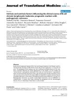
Báo cáo hóa học: " Nanogrids and Beehive-Like Nanostructures Formed by Plasma Etching the Self-Organized SiGe Islands" ppt
Bạn đang xem bản rút gọn của tài liệu. Xem và tải ngay bản đầy đủ của tài liệu tại đây (839.25 KB, 8 trang )
NANO EXPRESS
Nanogrids and Beehive-Like Nanostructures Formed by Plasma
Etching the Self-Organized SiGe Islands
Yuan-Ming Chang
•
Sheng-Rui Jian
•
Jenh-Yih Juang
Received: 19 April 2010 / Accepted: 25 May 2010 / Published online: 8 June 2010
Ó The Author(s) 2010. This article is published with open access at Springerlink.com
Abstract A lithography-free method for fabricating the
nanogrids and quasi-beehive nanostructures on Si sub-
strates is developed. It combines sequential treatments of
thermal annealing with reactive ion etching (RIE) on SiGe
thin films grown on (100)-Si substrates. The SiGe thin
films deposited by ultrahigh vacuum chemical vapor
deposition form self-assembled nanoislands via the strain-
induced surface roughening (Asaro-Tiller-Grinfeld insta-
bility) during thermal annealing, which, in turn, serve as
patterned sacrifice regions for subsequent RIE process
carried out for fabricating nanogrids and beehive-like
nanostructures on Si substrates. The scanning electron
microscopy and atomic force microscopy observations
confirmed that the resultant pattern of the obtained struc-
tures can be manipulated by tuning the treatment condi-
tions, suggesting an interesting alternative route of
producing self-organized nanostructures.
Keywords SiGe Á
High-resolution reciprocal space mapping Á SEM Á
AFM Á TEM
Introduction
Periodical nanostructures are of great research interest
because of their potential applications in data storage [1–3]
as well as in preparing photonic crystals [4, 5]. In order to
realize such opportunities, the development of lithography
techniques that are capable of fabricating large area peri-
odical nanostructures with reasonable control over their
size and periodicity is required. In general, two approaches,
namely the top–down and the bottom–up, have been coined
to label the techniques used to generate nanometer-sized
structures. The conventional lithographical methods,
including electron-beam lithography [6], photolithography
[7] and focused ion beam lithography [8], are the repre-
sentative top–down approaches widely implemented in
manufacturing nano-scale semiconductor devices as well
as nanostructures for various materials. However, these
techniques often require very high capital investment and
involve multiple-step processes, which not only limits the
facility accessibility but also results in relatively high
operation cost.
On the other hand, self-organized growth [9–11] has
been demonstrated to be a viable bottom–up method for
fabricating large area nanostructures with reasonable con-
trol of size and shape distributions. These structures can be,
in turn, used as templates for building nanometer-scale
structures. Here, we report a simple fabrication technique
capable of producing large area, well-ordered, periodic
nanogrids with sufficient size control in the sub-500-nm
region. The present method consists of two major steps.
First, the SiGe films deposited on Si substrates by ultrahigh
vacuum chemical vapor deposition (UHVCVD) were
transformed into self-assembled SiGe nanoisland arrays by
thermal annealing. Second, the resultant SiGe nano-island
arrays after subjected to subsequent reactive ion etching
(RIE) treatments were found to result in either the quasi-
beehive nanostructures or the self-organized nano-grids
(SONGs) on Si substrates, depending on the conditions of
RIE processes. It is noted that the current fabrication
Y M. Chang Á S R. Jian (&)
Department of Materials Science and Engineering,
I-Shou University, Kaohsiung 840, Taiwan
e-mail:
J Y. Juang
Department of Electrophysics, National Chiao Tung University,
Hsinchu 300, Taiwan
123
Nanoscale Res Lett (2010) 5:1456–1463
DOI 10.1007/s11671-010-9661-7
method is advantageous in several respects. First, since the
SiGe thin films were deposited in the UHVCVD system,
hence the issue of contamination during the annealing
process can be largely minimized. Moreover, owing to the
fact that no aqueous chemical solution and metallic mate-
rial were used in the manufacturing procedures, protection
of the RIE system from major pollution sources is guar-
anteed. Finally, the lithography-less anisotropic etching
process can reduce the fabrication cost significantly.
Experimental Details
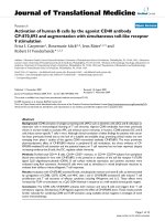
Figure 1 displays schematically the experimental proce-
dures carried out in this work for fabricating the quasi-
beehive Si nanostructures. Briefly, prior to the growth of
SiGe thin film, the surface of Si substrate was cleaned by
the standard Radio Corporation of America (RCA) proce-
dures [12]. The Si wafers were then dipped in dilute
hydrofluoric acid to form a passive surface layer, which
allowed the wafers to maintain their clean surfaces when
transported through air before being introduced into the
loadlock chamber of the ultrahigh vacuum chemical vapor
deposition (UHVCVD, ANELVA SRE-612 Japan) system
[13, 14]. When the temperature reached 550°C and the
deposition chamber was pumped to 1.2 9 10
-9
Torr using
a turbo molecular pump, the wafers were transferred
directly into the deposition chamber from the loadlock
chamber. The inlet gas was a mixture of Si
2
H
4
(flow rate:
1 sccm) and GeH
4
(flow rate: 7 sccm). The SiGe epitaxial
thin films were grown on the p-type Si (100) substrate at a
growth rate of *8 nm/min with a total thickness of about
100 nm (Fig. 1a) [15].
Following the film growth, in situ thermal annealing was
carried out at 900°C for 30 min in the UHVCVD chamber
to form the well-ordered SiGe nanoislands, as illustrated
schematically in Fig. 1b. The annealed SiGe/Si assembles
were then placed into the reactive ion etching (RIE, TEL
TE5000 Japan) chamber and, subjected to RIE using CF
4
(40 sccm) and argon (200 sccm) at an RF power of 200 W
for 3, 5, or 10 min, respectively, as depicted in Fig. 1c. The
effect of ion bombardment was primarily determined by
the ion energy, which, in turn, was dependent on the RF
power and the self-bias. During the RIE process, when the
reactive ions passed through the sheath region, the positive
ions were accelerated under the inserted electric field to
produce the ion bombardment effect that, in turn, etches the
target materials to form the quasi-beehive Si nanostructures
and the SONGs, as shown in Fig. 1d.
The high-resolution cross-sectional transmission elec-
tron microscopy (XTEM) image of thin film was analyzed
with an operating voltage of 200 kV. The composition of
the films was analyzed by Auger electron spectroscopy
(AES, VG Scientific Microlab 310F). The Auger analyses
were performed in a Physical Electronics-650 scanning
Auger microprobe with a background pressure of
1.0 9 10
-9
Torr. High-resolution X-ray diffraction was
used to determine the phase formation and crystallographic
structure of all samples. High-resolution reciprocal space
mapping (HRRSM) was applied to observe the structural
features of SiGe thin films. The characteristics of the sur-
face morphology of the Si substrate as well as that of the
SiGe films were observed by field-emission scanning
electron microscopy (FESEM). Atomic force microscopy
(AFM) was also used to image the surface morphologies of
the fabricated samples.
Results and Discussion
A XTEM image of the as-grown SiGe thin film is displayed
in Fig. 2. From the XTEM observation, the interface of
SiGe/Si is atomically smooth and flat with no sign of
existence of any misfit dislocations, indicating the com-
pletely coherent epitaxial relations between the film and
substrate. In addition, the AES results displayed in the inset
Fig. 1 Fabrication procedures of quasi-beehive Si nanostructures and
self-organized nanogrids: a SiGe thin film is deposited on Si
substrate; b SiGe islands arrays are formed via the annealing
treatment; c then plasma etching (RIE); d finally the self-organized
nanostructures are fabricated
Nanoscale Res Lett (2010) 5:1456–1463 1457
123
of Fig. 2 reveal that the Ge concentration is distributed
uniformly throughout the film on Si substrates. The aver-
aged Ge composition of the as-grown SiGe thin film was
estimated to be around 24.4%. It is surprising that, in the
present study, the apparent pseudomorphic growth of the
dislocation-free SiGe strained layer can maintain to a much
larger critical thickness than those reported previously [16,
17]. It is believed that the relative low growth temperature
might have played a significant role. As will be described
in more detail below, the strain relaxation and accompa-
nied surface roughening induced by subsequent thermal
annealing exhibited in the current films also displayed
marked differences comparing to those reported by Timb-
rell et al. [16] and Ozkan et al. [17], where generation of
dislocations and accompanied orientation change in surface
roughening morphologies were evidently observed.
Figure 3 shows the typical top-view image observed by
FESEM for SiGe films annealed at 900°C for 30 min. It is
clear that the high temperature annealing-induced surface
roughening has resulted in the formation of SiGe island
grids along the (100) and (010) directions. The cross-sec-
tional image of SiGe islands observed by XTEM displayed
in the inset of Fig. 3 further indicates that in the vicinity of
the interface between the SiGe islands and Si substrate
remains essentially free of relaxation dislocations during
the annealing process. Thus, the underlying mechanisms
leading to the present observations certainly require further
discussion. We first note that, unlike those reported by Xie
et al. [18] where the Ge islands have been deliberately
manipulated to nucleate on the intersections of misfit dis-
location networks generated at the interface of an under-
neath SiGe strain layer and Si substrate, the formation of
the present SiGe island array must have arisen from very
different mechanisms. On the other hand, Floro et al. have
demonstrated that heteroepitaxial stress between the SiGe
layer and Si substrate cannot only result in coherent
islanding of SiGe layer [19] but also have played the pri-
mary role in island shape transitions [20]. However, we
note that the abovementioned reports were all derived
based on observations performed during deposition, and
the islanding of the SiGe layer may behave differently from
that results from the post-deposition annealing. Indeed, as
pointed out by Jesson et al. [21] that, in the case of
annealed Si
x
Ge
1-x
films, especially at high supersatura-
tions, the strain-induced roughening can bypass faceting
and result in a transition with characteristics of the Asaro-
Tiller-Grinfeld (ATG) instability [22, 23]. Within the
context of the ATG instability, the strain field-induced
surface roughening of semiconductor films is manifested
by the appearance of continuous ripple morphology as
displayed in Fig. 3. The reason for this is that the Si
x
Ge
1-x
film is under compressive strain with e * -0.04 (1-x)
[24] such that an undulation in the surface allows lattice
planes to relax toward the ripple peaks. This lowers the
elastic energy stored in the strained film but, at the same
time, increases the surface energy relative to the planar
layer. The competition between these two factors, in turn,
gives rise to a condition for a minimum undulation length
Fig. 2 The cross-sectional HRTEM image of SiGe/Si sample prior to
thermal annealing. Inset compositions of Si and Ge elements are
confirmed by Auger analysis
Fig. 3 SEM observation the surface morphological image of SiGe
thin film at an annealing temperature of 900°C. Inset the XTEM
image of SiGe nanoislands on Si substrate
1458 Nanoscale Res Lett (2010) 5:1456–1463
123
scale k
c
for which the morphology is stable. Here, k
c
can be
expressed as following:
k
c
¼ 2plc=ð1 ÀmÞr
2
ð1Þ
with l, c, m, and r being the shear modulus, the surface
energy density, the Poisson’s ratio of the SiGe layer, and
the misfit stress, respectively. Taking l * 40 GPa [21],
c * 1 J/m
2
[21], m * 0.25,
1
and r * 1.4 GPa [19] one
obtains a k
c
* 170 nm, which is much smaller than the
averaged island spacing displayed in the inset of Fig. 3
(*400–500 nm) and those reported in Ref. [17]
(*600 nm). Therefore, the obtained morphology can be
indeed explained by the strain-induced roughening gov-
erned by the mechanism of ATG instability.
As has been pointed out by Jesson et al. [21], since there
is no energy barrier to roughening except for mass trans-
port along the surface, one of the consequences of the ATG
instability-induced islanding is the formation of cusp. In
order to elucidate this effect, Fig. 4 shows the relationship
of the depth of self-organized nanoislands as a function of
the annealing temperature for a fixed annealing time of
30 min. In this analysis, areas of 20 9 20 lm
2
of the
annealed SiGe thin films are measured at various annealing
temperatures. Based on these shape analyses, there are only
sparsely distributed convex structures on the surface of the
as-grown SiGe film. Even at the annealing temperature of
700°C, there are only few convex structures observed,
indicating that at temperatures lower than 700°C the strain-
induced roughening is hindered by either the lack of
supersaturation or insufficient time for adequate mass
transport. Nevertheless, as the annealing temperature is
above 800°C the measured depth of the SiGe islands
increases rapidly and reaches an average height of
*100 nm at 900°C, as shown in the inset of Fig. 4. In this
case, the cusp feature is evidently displayed in the inset of
Fig. 3 with the average depth being about the original film
thickness. At this stage, we believe that film must have
relaxed most of its strain.
In order to obtain a more quantitative measure on the
evolution of the structural quality upon annealing, we
chose the asymmetric (113)-reflection and the symmetric
(004)-reflection HRRSM to compare the characteristics of
the crystallographic structure of the as-grown SiGe sample
with the one annealed at 900°C for 30 min. Figs. 5a, b
reveal typical HRRSM around the asymmetric (113)
reflections of the as-grown SiGe sample and the annealed
sample, respectively. The HRRSM images are plotted on a
logarithmic scale as a function of the reciprocal lattice
vector parallel (Q
x
) and perpendicular (Q
y
) to the surface.
From Fig. 5a, it is clear that the scattering distributions of
the Si substrate and that of the SiGe thin film are in
perfect alignment, indicating that the SiGe thin film is
completely commensurate with the Si substrate. Moreover,
the scattering distributions of the SiGe film and substrate
are very narrow, indicative of the high crystalline quality
and the low defect density in the as-grown SiGe film. On
the other hand, Fig. 5b indicates that, after annealing at
900°C for 30 min, the scattering distributions of both
SiGe film and Si substrate broadened in two directions,
suggesting that significant degradation in crystallinity may
have occurred in both of the SiGe film and Si substrate.
This is consistent with the characteristics of ATG insta-
bility where the cusp regions are under tremendous
compressive strain and the transported mass is rapidly
accumulated at the island tips. The former is expected to
have effects on the substrate, while the latter is certainly
detrimental to the crystallinity of the resultant islands.
This can be further confirmed by the HRTEM images
displayed in Fig. 6, where the apparent degradation in the
crystalline structure of the annealed SiGe islands (Fig. 6b)
is clearly demonstrated by comparing that with the
as-deposited one (Fig. 6a). It is also noted that the center
of the scattering distribution of the SiGe film moves
toward that of the Si substrate, indicating that the
annealing processes has been accompanied by significant
strain relaxation. Based on the current HRRSM analyses,
the as-grown SiGe sample is apparently fully strained, and
about 36% of the strain has been relaxed by annealing the
sample at 900°C for 30 min.
Being inspired by defective structure revealed in the
HRRSM analyses presented in Fig. 5, we have further tried
Fig. 4 The depth of the self-organized nanoislands as a function of
the annealing temperature. Inset the shape analysis of SiGe thin film
with the annealing treatment at 900°C
1
Various values (ranging from 0.22 [23] to 0.28 [15]) of the
Poisson’s ratio for Si
x
Ge
1-x
films have been reported. Here, we take
an average value for estimation only.
Nanoscale Res Lett (2010) 5:1456–1463 1459
123
to use the annealed sample as the template for creating
various self-organized nanostructures. Fig. 7 presents one
of the examples we have tried. The series of the SEM
images shown in Fig. 7 display the surface morphology of
the as-grown SiGe sample (Fig. 7a) and that of samples
being first annealed at 900°C for 30 min followed by RIE
etching with CF
4
gas for 3, 5, and 10 min (Fig. 7b, d),
respectively. The surface morphology of as-grown SiGe
sample is very smooth with a surface roughness of
*0.32 nm over a 20 9 20 lm
2
area (Fig. 7a). After
annealing at 900°C (30 min) and RIE for 3 min, small
cavities are evidently generated (Fig. 7b), which more or
less following the island morphology shown in Fig. 3. Note
here that, when compared with the AFM image shown in
Fig. 7f for the same sample, in the SEM images displayed
in Fig. 7b, e the regions with the convex dome shape
appearance are in fact cavities while the light curvy lines
are the ridges of the cavities. This is also consistent with
the results reported by Oehrlein et al. [25]. In their studies,
the etching rate of Si
0.8
Ge
0.2
is more than two times faster
than that of pure Si when using CF
4
as the primary RIE gas.
In fact, it is generally conceived [26] that Ge is normally
more susceptible to fluorine and, as a result, higher amount
of fluoride (from CF
4
gas) often results in higher chemical
etching probability and more severe depredation in the
Fig. 5 Asymmetric (113) HRRSM of a the as-grown SiGe thin film
and, b the annealed SiGe thin film at 900°C for 30 min
Fig. 6 The HRTEM images of the a as-grown SiGe film and b SiGe
film annealed at 900°C for 30 min. The results clearly indicate the
degradation of crystalline structure resulted from the ATG instability-
induced surface roughening driven by strain relaxation
1460 Nanoscale Res Lett (2010) 5:1456–1463
123
original structural arrangements. In any case, Fig. 7
evidently displays that with the increasing RIE time the
nano-cavities grow bigger and deeper and finally form a
quasi-beehive surface structure on the Si substrate. The
results indicate that the amount and size of cavities and,
hence, the details of the quasi-beehive structure can be
closely monitored by controlling the RIE time.
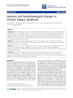
To fully realize the application potential, we have fur-
ther tried to develop methods of creating the nanostructures
with more regular spatial arrangements. To this respect,
instead of using the etching gases commonly used in the
RIE system, we changed to use Ar plasma treatment on the
annealed island array. To our surprise, even with as short as
1 min of Ar Plasma treatment, the highly concentrated and
regularly distributed nanogrids consisting of nano-cavities
and nano-tapers are clearly visible on Si substrate, as
shown in Fig. 8a, c, d. The average diameter, height,
and density of the nanocavities were *400–600 nm,
*50–80 nm, and *3–4 lm
-2
, respectively. With a slight
increase of Ar plasma treatment to 3 min, a significant
larger scale of nano-grids is obtained (Fig. 8b). It is noted
that Ar plasma treatment not only is very efficient in
Fig. 7 SEM top-view images of
SiGe thin films with a as-grown
sample, b 900°C annealed and
1 min RIE, c 900°C annealed
and 5 min RIE, and d 900°C
annealed and 10 min RIE. e The
SEM and f AFM image of the
quasi-beehive Si nanostructures
Nanoscale Res Lett (2010) 5:1456–1463 1461
123
removing the defective self-organized SiGe islands formed
after annealed at high temperatures but also is capable of
maintaining the original self-organized patterns to later
stages treatment. It is not clear at present why Ar plasma
treatment can make such a dramatic difference when
compared to that treated by more traditional RIE processes.
Presumably, since Ar plasma etching is a more physical
mean and no complicated chemical reactions are involved,
the etching is more isotropic and is easier to maintain the
original structural arrangements.
In any case, the present study has not only presented a
detailed account for the formation of the self-organized
nanoislands arrays by thermal annealing, but also has
indicated a very efficient method of producing the much
desired self-organized nano-grids (SONGs) on Si substrate
by using the self-organized nanoisland arrays as the
‘‘sacrificing’’ mask. We emphasize that the present pro-
cess has completely avoided the usage of any lithographic
process, which should be of significant practical impor-
tance in future applications. Experiments using these
SONGs nanostructure as the template substrate to
fabricate nanostructures of various interesting materials
are underway.
Conclusion
In summary, we have shown that it is possible to fabricate
self-organized nanogrids arrays on Si substrate by simply
combining the thermal annealing and RIE (or Ar plasma)
processes on the SiGe layers grown on Si substrate. The
compositions and structures of SiGe thin film are charac-
terized by using Auger and XTEM techniques to reveal
island formation mechanism. The results indicate that the
self-organized SiGe islands were formed via the Asaro-
Tiller-Grinfeld instability-induced surface roughening dri-
ven by the strain established between the heteroepitaxy
SiGe film and the Si substrate. A well-ordered self-orga-
nized nanogrids structure formed on the Si substrate was
successfully demonstrated by treating the annealed SiGe
film in Ar plasma for as short as only 1 min and without
resorting to any lithographical means.
Fig. 8 SEM top-view images of
SiGe thin films with a 900°C
annealed and 1 min Ar plasma,
b 900°C annealed and 3 min Ar
plasma. c 2-D and d 3-D AFM
images of the self-organized
nanogrids (a)
1462 Nanoscale Res Lett (2010) 5:1456–1463
123
Acknowledgments This work was partially supported by the
National Science Council of Taiwan, under Grant No.: NSC 97-2112-
M-214-002-MY2. JYJ is supported in part by the National Science
Council of Taiwan and the MOE-ATP program operated at NCTU.
The authors would like to thank Prof. Ching-Liang Dai (Department
of Mechanical Engineering, National Chung Hsing University, Tai-
wan) and Dr. Jiann Shieh and Hung-Min Chen (National Nano Device
Laboratories, Taiwan) for their useful discussions. Assistances from
Fu-Kuo Hsueh for UHVCVD, Chiung-Chih Hsu for TEM, Jie-Yi Yao
for XRD and Chih-Ming Wu for RIE technical supports in National
Nano Device Laboratories are also gratefully acknowledged.
Open Access This article is distributed under the terms of the
Creative Commons Attribution Noncommercial License which per-
mits any noncommercial use, distribution, and reproduction in any
medium, provided the original author(s) and source are credited.
References
1. J.Y. Cheng, C.A. Ross, V.Z. Chan, H.E.L. Thomas, R.G.H.
Lammertink, G.J. Vancso, Adv. Mater. 13, 1174 (2001)
2. S. Yoshida, T. Ono, M. Esashi, Nanotechnology 19, 475302
(2008)
3. X. Liu, M. Stamm, Nanoscale Res. Lett. 4, 459 (2009)
4. S.M. Yang, G.A. Ozin, Chem. Commun. 24, 2507 (2000)
5. M. Miyake, Y.C. Chen, P.V. Braun, P. Wiltzius, Adv. Mater. 21,
3012 (2009)
6. J. Fujita, Y. Ohnishi, Y. Ochiai, S. Matsui, Appl. Phys. Lett. 68,
1297 (1996)
7. J.G. Goodberlet, Appl. Phys. Lett. 76, 667 (2000)
8. N. Kawasegi, N. Morita, S. Yamada, N. Takano, T. Oyama,
K. Ashida, S. Momota, J. Taniguchi, I. Miyamoto, H. Ofune,
Nanotechnology 18, 375302 (2007)
9. Y. Xia, B. Gates, Y. Yin, Y. Lu, Adv. Mater. 12, 693 (2000)
10. Y.Z. Xie, V.P. Kunets, Z.M. Wang, V. Dorogan, Y.I. Mazur,
J. Wu, G.J. Salamo, Nano Micro Lett. 1, 1 (2009)
11. Z.M. Wang, K. Holmes, Y.I. Mazur, G.J. Salamo, Appl. Phys.
Lett. 84, 1931 (2004)
12. P.V. Zant, Microchip Fabrication. 5th edn, (McGraw-Hill, Bos-
ton, 2004), p 126
13. W.T. Lai, P.W. Li, Nanotechnology 18, 145402 (2007)
14. D.J. Bell, T.E. Bauert, L. Zhang, L.X. Dong, Y. Sun,
D. Gru
¨
tzmacher, B.J. Nelson, Nanotechnology 18, 055304 (2007)
15. M. Huang, C.S. Ritz, B. Novakovic, D. Yu, Y. Zhang, F. Flack,
D.E. Savage, P.G. Evans, I. Knezevic, F. Liu, M.G. Lagally, ACS
Nano 3, 721 (2009)
16. P.Y. Timbrell, J.M. Baribeau, D.J. Lockwood, J.P. McCaffrey, J.
Appl. Phys. 67, 6292 (1990)
17. C.S. Ozkan, W.D. Nix, H. Gao, Appl. Phys. Lett. 70, 2247 (1997)
18. Y.H. Xie, S.B. Samavedam, M. Bulsara, T.A. Langdo, E.A.
Fitzgerald, Appl. Phys. Lett. 71, 3567 (1997)
19. J.A. Floro, E. Chason, R.D. Twesten, R.Q. Hwang, L.B. Freund,
Phys. Rev. Lett. 79, 3946 (1997)
20. J.A. Floro, G.A. Lucadamo, E. Chason, L.B. Freund, M. Sinclair,
R.D. Twesten, R.Q. Hwang, Phys. Rev. Lett. 80, 4717 (1998)
21. D.E. Jesson, K.M. Chen, S.J. Pennycook, T. Thundat, R.J. War-
mack, J. Electron. Mater. 26, 1039 (1997)
22. R.J. Asaro, W.A. Tiller, Metall. Trans. 3, 1789 (1972)
23. M.A. Grinfeld, Sov. Phys. Dokl. 31, 831 (1986)
24. H.T. Johnson, L.B. Freund, J. Appl. Phys. 81, 6081 (1997)
25. G.S. Oehrlein, G.M.W. Kroesen, E. de Fre
´
sart, Y. Zhang, T.D.
Bestwick, J. Vac. Sci. Technol. A 9, 768 (1991)
26. Y. Zhang, G.S. Oehrlein, E. de Fre
´
sart, J. Vac. Sci. Technol. A
11, 2492 (1993)
Nanoscale Res Lett (2010) 5:1456–1463 1463
123