Báo cáo hóa học: " Negative Differential Resistance in ZnO Nanowires Bridging Two Metallic Electrodes" ppt
Bạn đang xem bản rút gọn của tài liệu. Xem và tải ngay bản đầy đủ của tài liệu tại đây (371.43 KB, 4 trang )
NANO EXPRESS
Negative Differential Resistance in ZnO Nanowires Bridging
Two Metallic Electrodes
Yang Zhang
•
Ching-Ting Lee
Received: 14 May 2010 / Accepted: 3 June 2010 / Published online: 13 June 2010
Ó The Author(s) 2010. This article is published with open access at Springerlink.com
Abstract The electrical transport through nanoscale
contacts of ZnO nanowires bridging the interdigitated Au
electrodes shows the negative differential resistance (NDR)
effect. The NDR peaks strongly depend on the starting
sweep voltage. The origin of NDR through nanoscale
contacts between ZnO nanowires and metal electrodes is
the electron charging and discharging of the parasitic
capacitor due to the weak contact, rather than the con-
ventional resonant tunneling mechanism.
Keywords Negative differential resistance Á
ZnO nanowires Á Electrical transport
Introduction
In recent years, there has been a growing interest in the
exploration of the charge transport through nanoscale low-
dimensional systems [1, 2]. An important phenomenon of
electronic transport in low-dimensional systems is the
negative differential resistance (NDR) effect in current–
voltage (I–V) curve [3, 4]. This effect can be used in
switches and high-frequency oscillators [5]. This phe-
nomenon has been impressively demonstrated in low-
dimensional structures [6, 7]. Usually, this NDR effect can
be attributed to the intrinsic resonance tunneling, experi-
mentally or theoretically [8, 9]. The coupling mechanism
for NDR in junctions was also proposed [10]. The tun-
neling current usually depends on the transition in low-
dimensional structures or in the interface between the metal
electrodes and nanoscale structures [11]. Particularly, the
NDR behavior in transport properties of the nanojunction
strongly depends on the quantum nature of the nanowire
and the metal contacts [12]. Therefore, the contact between
the nanowire and metal electrodes greatly affects the I–V
characteristics [13].
In this work, we report on the experimental observation
of the voltage-controlled NDR behavior in ZnO nanowires
bridging the interdigitated Au electrodes. The current peak
of NDR in the I–V curves depends on the bias sweep
direction and the starting voltage. This NDR phenomenon
is attributed to the electron charging and discharging of the
parasitic capacitor rather than the conventional tunneling
electrical transport across the junctions.
Experimental Details
ZnO nanowires were grown on Si substrates by a low-
pressure chemical vapor deposition process. Si substrates
were cleaned with a wet chemical method and put in the
downstream of Zn grains. After the system was pumped
down to 1 Torr, argon gas was introduced at a constant
flow rate of 200 sccm. When the temperature of the furnace
was raised to 400°C at a ramp rate of 20°C/min, oxygen
was introduced into the system at 20 sccm. Then, the
temperature of the furnace was heated up to 650°C and
maintained for 30 min. Finally, the system was cooled
down to room temperature naturally. ZnO nanowires were
dispersed into the ethanol by ultrasonication. SiO
2
/Si
Y. Zhang (&)
Institute of Physics for Microsystems and Department of
Physics, Henan University, No. 1 Jinming Road, Kaifeng,
Henan 475004, China
e-mail:
C T. Lee
Institute of Microelectronics, Department of Electrical
Engineering, National Cheng Kung University, Tainan 70101,
Taiwan
123
Nanoscale Res Lett (2010) 5:1492–1495
DOI 10.1007/s11671-010-9667-1
substrates (thermal oxide thickness is 500 nm) with pat-
terns of interdigitated Au electrodes were immersed into
this ethanol solution of ZnO nanowires. After the ethanol
solution was evaporated, ZnO nanowires were placed on
Au electrodes. Ti/Au (250/1,000 A
˚
) contact electrodes
were deposited by thermal evaporation, and patterned with
interdigitated structures by a photolithographic technique.
ZnO nanowires on interdigitated metallic electrodes were
observed by field emission scanning electron microscopy
(FE-SEM, JEOL JSM-7000F). I–V and C–V measurements
were conducted on an HP 4156 C semiconductor parameter
analyzer and an HP 4284A LCR Precision Meter,
respectively.
Results and Discussion
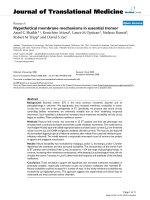
Figure 1 shows a typical SEM image of ZnO nanowires
bridging the interdigitated Au electrodes. It can be clearly
seen that there are only a few of ZnO nanowires on the
pattern of interdigitated Au electrodes. The typical ZnO
nanowire (shown in the inset in Fig. 1) reveals that the
length and diameter of ZnO nanowire is *30 lm and
*100 nm, respectively. An individual ZnO nanowire
bridged the gap between two electrodes.
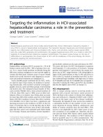
Figure 2a shows the I–V characteristics of ZnO nano-
wires bridged Au electrodes at different applied voltages in
the range of -4to4V,-10 to 10 V, and -15 to 15 V.
The voltages were swept in the negative direction and then
in the positive direction. In Fig. 2a, all the I–V curves show
a similar shape, in which NDR effect can be clearly
observed. Also, we can see that the position of the NDR
peak varied with the starting voltages. When the value of
the starting sweep voltages was increased, the peak voltage
and peak current were increased. These results indicate that
the starting sweep voltage plays a crucial role in the NDR
position. From Fig. 2a, it can be clearly seen that all I–V
curves do not pass through the origin point. When the
absolute value of the starting sweep voltage increases, the
absolute values of the currents of the intersections with two
coordinate axes increase. Therefore, the NDR position and
the intersections with two coordinate axes depend on the
starting sweep voltage.
To understand the effect of the starting sweep voltage on
the NDR peak, the I–V characteristics were measured under
forward and reverse bias from 0 to 4 V, and from 0 to
-4 V, and shown in Fig. 2b. However, whether under the
positive or negative bias NDR effect was not observed in
each curve. Moreover, it should be noted that when the
Fig. 1 SEM image of ZnO nanowires bridging the interdigitated Au
electrodes. The inset is the enlarged image of the selected area in
SEM image
-12 -8 -4 0 4 8 12
-60
-50
-40
-30
-20
-10
0
10
20
3.4 V, 15.2 nA
2.9 V, 11.3 nA
1.4 V, 5.94 nA
Current (nA)
Voltage (V)
-4 to 4 V
-10 to 10 V
-15 to 15 V
(a)
-4 -3 -2 -1 0 1 2 3 4
-10
-8
-6
-4
-2
0
2
4
6
8
10
12
Current (nA)
Volta
g
e (V)
0 to 4 V
4 to 0 V
0 to -4 V
-4 to 0 V
(b)
Fig. 2 a Current–voltage characteristics of ZnO nanowires bridging
metal electrodes at different applied voltages in the range of -4to
4V,-10 to 10 V, and -15 to 15 V. b Current–voltage character-
istics of ZnO nanowires bridging metal electrodes under forward and
reverse bias conditions between 0 and 4 V
Nanoscale Res Lett (2010) 5:1492–1495 1493
123
starting voltage is 4 or -4 V, the current is not zero at the
ending voltage of 0 V. These results indicate the charges
accumulate in the structure of ZnO nanowires bridging
metal electrodes when the starting voltage is not zero. The
charging and discharging processes may take place under
bias voltage. However, the NDR resulting from resonant
tunneling can be observed usually when the starting sweep
voltage is zero [14, 15].
At the same time, we also fabricated several other
similar devices with different numbers of ZnO nanowires
put on the Au electrodes with the same interdigitated pat-
tern using the aforementioned method. We observed sim-
ilar NDR behavior in the I–V curve for each device. The
NDR peak was dependent on the sweep voltage applied to
ZnO nanowires bridging the interdigitated Au electrodes.
However, the NDR peak position varied with changes in
the number of ZnO nanowires. The ZnO nanowires/Au
contacts having different ZnO nanowires result in different
capacitance. Nevertheless, it is difficult to control the
number of ZnO nanowires using this solution dispersion
method. We will modify the nanowire dispersion method to
improve the dispersion of ZnO nanowires, and further
investigate the effect of the number of ZnO nanowires on
the NDR peak current and voltage.
To identify the charging and discharging processes
under bias voltage, C–V measurements were performed in
the range of 1 kHz to 1 MHz. Frequency-dependent C–V
characteristics of ZnO nanowires bridged metal electrodes
is shown in Fig. 3. It can be seen that the different
behaviors of the capacitance has a function of the fre-
quency. At high frequencies, the capacitance hardly chan-
ged, even decreased at higher frequencies. It should be
noted that at low frequencies, the capacitance increases
with the bias voltage. The frequency dependence is due to
the carrier response time. It is reported that the interface
states do not respond to the high-frequency signal [16].
These results suggest that this structure can trap a large
number of electronic charges, just as capacitors have the
ability of holding charges at low frequencies. For ZnO
nanowires–bridged metal electrodes, a number of devices
must typically be connected in parallel and cause parasitic
capacitances. These results confirmed the capacitor effect
in the structure of ZnO nanowires in weak contact to two
metal electrodes.
In order to explain the behavior of current, the typical
scheme of nonlinear current trace is shown in Fig. 4a. In
Fig. 4a, the sweep bias voltage was divided into five
regions according to five distinct changes in the current
curve. The suggested circuits of the charging and dis-
charging processes under the bias voltage are shown in
Fig. 4b. At the beginning of sweeping, the value of starting
current is very larger, and then decreases drastically from
A to B with decreased sweep voltage. The parasitic
capacitor at the weak interface contact between ZnO
nanowires and two metal electrodes is empty. So, a larger
number of charges can be stored in this parasitic capacitor.
Thus, a larger current flowed through the system at the
beginning stage of sweeping. However, because the abso-
lute value of sweep voltage drops down linearly, and the
parasitic capacitor has been charged, the absolute value of
current decreases nonlinearly, as shown in I region in
Fig. 4a. When the bias voltage is V
B
, the parasitic capacitor
starts to saturate, and starts discharging. The current
direction of discharging of the parasitic capacitor is
opposite to that of applied voltage. Thus, the current at V
B
is zero. When the bias voltage is in the II region, the
current direction of discharging of the parasitic capacitor
dominates. The bias voltage is negative, but the current
direction is positive. When the bias voltage is zero
(V
C
= 0), the current in the system is completely domi-
nated by the discharging of the parasitic capacitor.
When the bias voltage is positive, both the current
directions resulting from the bias voltage and the dis-
charging of the parasitic capacitor are the same. So, the
current in III region (V is from V
C
to V
D
) goes up greatly
and reached maximum when V is V
D
. Subsequently, the
parasitic capacitor starts to be charged. A larger number of
electron charges are stored. This leads to a decrease of
current. Thus, NDR effect can be observed clearly, as
shown in IV region in Fig. 4a. Finally, the current is
reduced to a minimum when the parasitic capacitor is fully
charged in the opposite direction compared with the start-
ing sweep voltage (V is V
E
). When the bias voltage is
larger than V
E
, the total current increases slowly in spite of
discharging from the parasitic capacitor. Therefore, the
charging and discharging effects of a parasitic capacitor
can be used to explain the I–V characteristics of the weak
contact interfaces between ZnO nanowires and metal
electrodes.
02468101214
17
18
19
20
21
22
23
Capacitance (pF)
Bias voltage (V)
1 kHz
2 kHz
10 kHz
50 kHz
1 MHz
Fig. 3 Frequency-dependent C–V characteristics of ZnO nanowires–
bridged metal electrodes from 1 kHz to 1 MHz
1494 Nanoscale Res Lett (2010) 5:1492–1495
123
Conclusions
In conclusion, ZnO nanowires were prepared by a low-
pressure chemical vapor deposition process and bridged on
the interdigitated Au electrodes. NDR in the I–V curves of
ZnO nanowires bridging the interdigitated Au electrodes
has been observed. NDR performance can be controlled by
the bias voltage. The NDR peak voltage and peak current
are influenced strongly by the value of starting voltage. The
origin of this NDR is the charging and discharging effect
between ZnO nanowires and metal electrodes rather than
the conventional resonant tunneling mechanism. The weak
nanoscale contact between ZnO nanowires and metal
electrodes forms the parasitic capacitor. The frequency-
dependent C–V measurements further demonstrated the
charging and discharging processes. Such NDR effect in
the metal/nanowires/metal structure has important potential
applications in nanowire-based switches, oscillators, and
resonators.
Acknowledgments The authors thank Prof. Liren Lou at University
of Science and Technology of China for his helpful discussions. Y.
Zhang acknowledges support from the Department of Education of
Henan Province, China (No. 2009A140002).
Open Access This article is distributed under the terms of the
Creative Commons Attribution Noncommercial License which per-
mits any noncommercial use, distribution, and reproduction in any
medium, provided the original author(s) and source are credited.
References
1. J.P. Colinge, C.W. Lee, A. Afzalian, N.D. Akhavan, R. Yan, I.
Ferain, P. Razavi, B. O’Neill, A. Blake, M. White, A.M. Kelle-
her, B. McCarthy, R. Murphy, Nature Nanotech. 5, 225 (2010)
2. S L. Chen, P.B. Griffin, J.D. Plummer, IEEE Trans. Electron
Devices. 56, 634 (2009)
3. L. Esaki, L.L. Chang, Phys. Rev. Lett. 33, 495 (1974)
4. M. Dragoman, G. Konstantinidis, A. Cismaru, D. Vasilache, A.
Dinescu, D. Dragoman, D. Neculoiu, R. Buiculescu, G. Deli-
georgis, A.P. Vajpeyi, A. Georgakilas, Appl. Phys. Lett. 96,
053116 (2010)
5. E. Lo
¨
rtscher, J.M. Tour, J.W. Ciszek, H. Riel, J. Phys.: Confer-
ence Series. 61, 987 (2007)
6. B. Chitara, D.S.I. Jebakumar, C.N.R. Rao, S.B. Krupanidhi,
Nanotechnology. 20, 405205 (2009)
7. P.C. Jangjian, T.F. Liu, M.Y. Li, M.S. Tsai, C.C. Chang, Appl.
Phys. Lett. 94, 3105 (2009)
8. S. Sen, S. Chakrabarti, J. Phys. Chem. C. 112, 15537 (2008)
9. T.A. Khachaturova, A.I. Khachaturov, J. Exp. Theor. Phys. 107,
864 (2008)
10. R. Pati, M. McClain, A. Bandyopadhyay, Phys. Rew. Lett. 100,
246801 (2008)
11. J.W.G. Wildo
¨
er, L.C. Venema, A.G. Rinzler, R.E. Smalley, C.
Dekker, Nature. 391, 59 (1998)
12. S.H. Ke, H.U. Baranger, W. Yang, Phys. Rev. Lett. 99, 146802
(2007)
13. J.M. Beebe, B.S. Kim, J.W. Gadzuk, C.D. Frisbie, J.G. Kushm-
erick, Phys. Rev. Lett. 97, 26801 (2006)
14. N. Simonian, J. Li, K. Likharev, Nanotechnology. 18, 424006
(2007)
15. R.C. Bowen, G. Klimeck, R.K. Lake, W.R. Frensley, T. Moise, J.
Appl. Phys. 81, 3207 (1997)
16. B.L. Swenson, U.K. Mishra, J. Appl. Phys. 106, 064902 (2009)
V
B
V
E
V
D
V
C
V
A
V
IV
III
II
E
D
C
B
Current (a.u.)
Voltage (V)
A
I
(a)
0
(b)
Fig. 4 a Typical scheme of
nonlinear current trace. b The
suggested circuits of the
charging and discharging
processes under the bias voltage
Nanoscale Res Lett (2010) 5:1492–1495 1495
123