Báo cáo hóa học: " Multi-Directional Growth of Aligned Carbon Nanotubes Over Catalyst Film Prepared by Atomic Layer Deposition" doc
Bạn đang xem bản rút gọn của tài liệu. Xem và tải ngay bản đầy đủ của tài liệu tại đây (496.99 KB, 6 trang )
NANO EXPRESS
Multi-Directional Growth of Aligned Carbon Nanotubes Over
Catalyst Film Prepared by Atomic Layer Deposition
Kai Zhou
•
Jia-Qi Huang
•
Qiang Zhang
•
Fei Wei
Received: 18 May 2010 / Accepted: 12 June 2010 / Published online: 23 June 2010
Ó The Author(s) 2010. This article is published with open access at Springerlink.com
Abstract The structure of vertically aligned carbon
nanotubes (CNTs) severely depends on the properties of
pre-prepared catalyst films. Aiming for the preparation of
precisely controlled catalyst film, atomic layer deposition
(ALD) was employed to deposit uniform Fe
2
O
3
film for the
growth of CNT arrays on planar substrate surfaces as well
as the curved ones. Iron acetylacetonate and ozone were
introduced into the reactor alternately as precursors to
realize the formation of catalyst films. By varying the
deposition cycles, uniform and smooth Fe
2
O
3
catalyst films
with different thicknesses were obtained on Si/SiO
2
sub-
strate, which supported the growth of highly oriented
few-walled CNT arrays. Utilizing the advantage of ALD
process in coating non-planar surfaces, uniform catalyst
films can also be successfully deposited onto quartz fibers.
Aligned few-walled CNTs can be grafted on the quartz
fibers, and they self-organized into a leaf-shaped structure
due to the curved surface morphology. The growth of
aligned CNTs on non-planar surfaces holds promise in
constructing hierarchical CNT architectures in future.
Keywords Aligned carbon nanotubes Á
Atomic layer deposition Á Chemical vapor deposition Á
Catalysis Á Nanotechnology
Introduction
Vertically aligned carbon nanotube (CNT) arrays were
composed of aligned CNTs and possessed outstanding
performances in materials science, catalysis, optics, elec-
trics, and energy conversion/storage. Numerous functional
applications, such as nano-brushes, field emitters, catalyst
and catalyst supports, electronic electrodes, shock absorb-
ing, energy conversion and storage, have been proposed
[1–5]. The performance of aligned CNTs depends highly
on the intrinsic structure of CNTs as well as the organi-
zation of CNTs. For example, large specific surface area
(small CNT diameter and wall number) and suitable pore
size distribution (hierarchical array structures) were
required for the application of aligned CNT arrays in
supercapacitor [6]. Therefore, the modulations of the CNT
structure and their organization were of common interest in
the research of CNT arrays.
Precisely controlled catalyst layers were widely used to
modulate the metal catalyst particle size and therefore the
structure of CNTs in the arrays. Generally, thin catalyst film
favored the synthesis of CNTs with few walls. Physical
vapor deposition (PVD, such as electron beam evaporation
and magnetic sputtering) was one of the most popular
methods for the deposition of uniform catalyst films on
substrates [1, 7–9]. The wall number distribution of CNTs
has been successfully controlled by modulating the thick-
nesses of Fe catalyst films [9]. Some endeavors on modu-
lating the CNT structure by delicately controlled growth
parameters were also made [10]. However, it must be
noticed that, up to now, precise deposition of metal catalyst
film on a non-planar surface was still difficult. Therefore, it
is hard to synthesize aligned few-walled CNTs on a non-
planar surface [11], which brings difficulties in constructing
multi-stage aligned CNTs on non-planar substrates.
Electronic supplementary material The online version of this
article (doi:10.1007/s11671-010-9676-0) contains supplementary
material, which is available to authorized users.
K. Zhou Á J Q. Huang Á Q. Zhang Á F. Wei (&)
Beijing Key Laboratory of Green Chemical Reaction
Engineering and Technology, Department of Chemical
Engineering, Tsinghua University, 100084 Beijing, China
e-mail:
123
Nanoscale Res Lett (2010) 5:1555–1560
DOI 10.1007/s11671-010-9676-0
On the other hand, CNT arrays can be facilely synthe-
sized on non-planar surfaces through floating catalyst
chemical vapor deposition (CVD) [12]. Catalyst particles
were in situ formed on substrates during the growth process
of aligned CNTs [12–14]. Various functional materials with
complex structures, such as CNT flowers [12, 15], CNT
brushes [2, 16–18], CNT polyhedrons [19], CNT tubes [20,
21], have been fabricated. However, the catalyst particles
formed by the decomposition of catalyst precursor were
easily agglomerated into large ones and this gave rise to
CNT arrays composed of large-diameter multi-walled CNTs
(with diameters mainly in the range of 10–200 nm) [12].
Consequently, the as-obtained aligned CNTs were with
limited specific surface area (lower than 200 m
2
/g). This is
still an obstacle for the further applications of hierarchical
CNTs. Under the state-of-the-art of CNT array synthesis, the
construction of multi-stage CNT arrays composed of thin
CNTs on non-planar surface was still an obstacle. Consid-
ering the hardness in controlling catalyst sizes during
floating catalyst process, a method for the uniform coating
of catalysts on non-planar substrate should be developed.
Recently, atomic layer deposition (ALD) has become an
important way to fabricate thin film on various substrates. It is
a thin film growth method based on sequential, self-limiting
surface reactions that can deposit conformal thin films with
excellent conformal step coverage and is ideal for the depo-
sition on complex non-planar surface topography [22, 23]. It
is a powerful tool to fabricate thin film on irregular or porous
substrate. For instance, Liu et al. reported the deposition of
platinum nanoparticles on CNTs by ALD for the application
in proton-exchange membrane fuel cells [24]; ALD was also
employed to grow coaxial thin films of Al
2
O
3
[25], V
2
O
5
,
TiO
2
,HfO
2
,[26, 27], and Al
2
O
3
/W bilayers [25]onCNTs.
Recently, Amama et al. reported the preparation of alumina
layer as Fe catalyst support through ALD process for CNT
growth. It should be noticed that the metal film was still
prepared by electron beam evaporation [28]. Direct fabrica-
tion of metal catalyst film served as active phase for CNT
growth is still an open question.
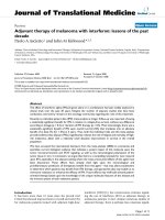
In this contribution, we developed a method using ALD
to prepare uniform metal catalyst films for aligned CNT
growth. As illustrated in Fig. 1, various kinds of substrates,
such as wafers and quartz fibers, were selected as sub-
strates for the deposition of Fe
2
O
3
film by ALD. Iron
acetylacetonate and ozone were introduced into the reactor
alternately as precursors for the preparation of Fe
2
O
3
films
through the following chemical reaction:
During ALD process, iron source was imported into the
reactor and a self-terminating reaction occurred on the
substrate surface. After a purging of inert gas N
2
to remove
the non-reacted reactants and gaseous by-products, mono-
layer iron compounds were adsorbed. As ozone oxidized
the iron compounds, monolayer iron oxides were obtained
during a cycle. After a purge to evacuate ozone and by-
products, the deposition process continued next cycle, and
the thicknesses of Fe
2
O
3
films were controlled by varying
the reaction cycles. After the deposition of catalysts, the
substrates were transferred into tubular furnace and
annealed under hydrogen atmosphere to reduce iron oxides
into Fe catalysts. The CVD process was then conducted for
the growth of aligned few-walled CNTs. Since the catalyst
films were deposited on all the surfaces exposed to the
Fig. 1 Schematic illustration of the ALD and CVD process for the
synthesis of CNT arrays
1556 Nanoscale Res Lett (2010) 5:1555–1560
123
gaseous precursors in ALD process, few-walled CNT
arrays can radially grow on fibrous substrates.
Experimental
Preparation of Catalyst Film by ALD Method
Silicon wafer (with 700 nm SiO
2
layer) coated with 10-nm-
thick Al
2
O
3
by e-beam evaporation and quartz fibers with a
diameter of about 10 lm were employed as substrates for
ALD deposition. The iron source was Fe(acac)
3
(iron(III)
acetylacetonate, Alfar, [99.99%) and ozone served as
oxidants was supplied from an ozone generator with oxy-
gen (Beiwen Gas, purity [99.999%) as input. The output
ozone concentration is 7 vol%. N
2
was used as both carrier
gas for iron source and the purge gas for ALD deposition.
Thin catalyst films were deposited in a 3 L vacuum
chamber. The precursors (iron sources and oxidants) were
pulsed alternately into the reactor, separated by N
2
gas
purge (purity [99.999%) to realize the ALD deposition.
The films were deposited at a pressure of about 100–500 Pa
in the temperature of 230°C. The iron source was sublimed
at 80°C and carried into the reactor by N
2
. Each ALD cycle
consisted of 100-s Fe(acac)
3
pulse, 3-s N
2
purge pulse, 10-s
ozone pulse, and 3-s N
2
purge pulse. Various cycles of
ALD deposition were conducted on both wafer and quartz
fiber to obtain Fe
2
O
3
catalyst films.
Synthesis of Aligned CNTs on ALD Catalysts
Substrates were transferred into horizontal quartz-tube-
reactor set in a tube furnace for the CVD synthesis of
aligned CNTs. The temperature of the reactor increased to
750°C under the protection of Ar and H
2
.C
2
H
4
together
with CO
2
was then introduced to realize the growth of CNT
arrays. The typical flow rates of Ar, H
2
,C
2
H
4
, and CO
2
were 250, 200, 100, and 50 sccm, respectively. After a 1-h
growth of aligned CNTs, the feedstock of C
2
H
4
and CO
2
was terminated, and the reactor was cooled down under the
protection of Ar and H
2
.
Characterization
The catalyst layers deposited by ALD process were char-
acterized with X-ray photoelectron spectroscopy (XPS,
PHI Quantera SXM) and atomic force microscope (AFM,
Nanoman VS). High-resolution scanning electron micros-
copy (SEM, JSM 7401F operating at 5.0 kV) was used to
characterize the morphology of the CNT arrays. High-
resolution transmission electron microscopy (TEM, JEM
2010 operating at 120.0 kV) was used to determine the
detailed structure of the CNTs in the arrays. Raman spec-
troscopy of the CNTs was performed using a Raman
microscope (Renishaw, RM2000, He–Ne laser excitation
line 633.0 nm).
Results and Discussion
Silicon wafer was selected as a model substrate to dem-
onstrate the deposition of Fe
2
O
3
film and the synthesis of
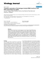
aligned CNTs. To confirm the deposition of Fe
2
O
3
film by
ALD, XPS was collected from the Fe
2
O
3
/Al
2
O
3
(10 nm)/
SiO
2
(700 nm)/Si substrate. O, Al, and Fe elements can be
detected (Fig. 2a). The XPS data of different ALD cycles
revealed a positive relationship between the Fe content and
the ALD cycle number (Fig. 2b). An Fe abundance of ca.
1% was detected on the surface of Fe
2
O
3
/Al
2
O
3
(10 nm)/
SiO
2
(700 nm)/Si obtained by 10 ALD cycles. It increased
to over 6% after 40 ALD cycles. This confirmed that the Fe
has been successfully deposited and the thickness of Fe
2
O
3
film on the surface increased with ALD cycles. As the
growth of CNT arrays was sensitive to the surface mor-
phologies of substrates, the planarity after ALD deposition
was also investigated using AFM. Figure S1a showed the
AFM topography images of original silicon substrate with
Al
2
O
3
barrier layer and the substrate with 10, 20, 30 ALD
Fig. 2 a Typical XPS data on
substrate surface with Fe
2
O
3
deposited by 30 ALD cycles; b
Iron concentration at the surface
of Fe
2
O
3
/Al
2
O
3
(10 nm)/
SiO
2
(700 nm)/Si after different
ALD cycles
Nanoscale Res Lett (2010) 5:1555–1560 1557
123
cycles. The original substrate showed a relatively smooth
and uniform surface, and only a few particles can be
observed, showing high planarity of the thin Al
2
O
3
film. A
few small particles were generated on the substrate surface
during the ALD process. The average roughness increased
gradually from 0.15 to 0.30 nm with the ALD cycles
increasing from 0 to 30 cycles. Though the roughness of
substrate increased slightly, it maintained good planarity
for the growth of aligned CNTs.
After the deposition of Fe
2
O
3
films on silicon wafer,
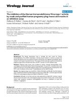
CVD growth was conducted. Figure 3a showed the
as-obtained aligned CNTs on substrate with 40 ALD cycles
for catalyst deposition, which possessed a uniform top
surface. After the reduction of metal catalysts and the
introduction of carbon source, high-density Fe nanoparti-
cles formed, and aligned CNTs synchronously grew on the
wafer. Figure 3b showed the CNT arrays on both the top
surface (with Al
2
O
3
barrier layer) and side cross-section
(without SiO
2
and Al
2
O
3
barrier layer). The height of CNT
arrays on the top surface (200 lm) was much higher
compared with that on the side cross-section (30 lm) due
to the existence of barrier layers. As reported previously,
the barrier layers can supply more nucleation sites on the
surface by increasing the surface roughness and to resist
the sintering of Fe nanoparticles due to the stronger sub-
strate catalyst interaction [29–31]. Radial growth of CNTs
on a wafer illustrated in Fig. 3b suggested that the Fe
catalyst film was coated onto all the surfaces of the sub-
strate. Thus, uniform catalyst films on all surfaces of sub-
strate can be deposited by ALD, which provides a facile
way to prepare catalyst film for multi-directional growth of
aligned CNTs.
TEM characterization was performed to determine the
detailed structure of CNTs in the arrays. Figure 3d is the
typical low-magnification TEM image of the CNTs derived
on the substrate with 40 ALD cycles of Fe
2
O
3
deposition.
The samples mainly consisted of few-walled CNTs. Fig-
ure 3e showed a triple-walled CNT with an outer diameter
of 8.7 nm. Based on the statistic results, CNTs obtained
with different ALD cycles for Fe
2
O
3
deposition showed
outer diameters ranging from 7 to 12 nm and wall numbers
of 3-6. The top part of CNT arrays with different ALD
cycles was further examined by Raman spectroscopy
(Fig. 3f). The Raman spectra showed two main peaks: D
peak around 1,325 cm
-1
and G peak around 1,580 cm
-1
,
corresponding to the signal of disordered and ordered
graphite structures. Therefore, the intensity ratio of G peak
to D peak was widely used in determining the graphitiza-
tion degree of CNTs. As calculated, the I
G
/I
D
ratio kept at
about 0.72 for the CNTs derived on substrate with 10- to
30-ALD cycle catalyst film. The relatively low I
G
/I
D
ratio
may be attributed to the large diameters and high defect
densities of the CNTs [10]. The I
G
/I
D
ratio decreased to
0.58 for the CNT arrays obtained on substrates with 40
ALD cycles, which can be attributed to higher surface
roughness and the non-uniform catalyst particles.
The synthesis of CNT arrays on non-planar surfaces was
important to explore the applications of CNTs in com-
posites, electrodes, biology and catalyst supports. Due to
the difficulty in the preparations of uniform catalyst layers
through PVD process on non-planar surfaces, the synthesis
of uniform aligned CNTs on all surface of substrate was
only achieved by floating catalyst process and impregna-
tion process [2, 16, 32–34]. Yamamotoa et al. [32] soaked
Fig. 3 a Top surface ofuniform aligned CNTs grown on wafer; b Aligned
CNTs grown on top and side surface of wafer; c High-magnification
SEM image of aligned CNTs; d Low- and e high-magnification TEM
images of CNTs grown on wafer with 40 ALD cycles; f Raman spectrum of
aligned CNTs grown on Si wafer with different ALD cycles
1558 Nanoscale Res Lett (2010) 5:1555–1560
123
ceramic fibers in a solution of iron nitrate and placed fibers
into tube furnace for CVD process. Radial growth of
aligned multi-walled CNTs with an outer diameter of
17.1 nm was realized [32]. However, catalyst preparation
for the growth of few-walled CNTs arrays on curved sur-
face was still a challenge. Inspired by the growth of CNTs
on all the surfaces of Si wafers, we conducted the ALD
deposition of Fe
2
O
3
catalyst on the quartz fiber with a
diameter of about 10 lm and realized the synthesis of
uniform few-walled CNT arrays on the curved surface. As
shown in Fig. 4a, though the surface was composed of
SiO
2
without Al
2
O
3
layer, long CNT arrays (over 100 lm)
formed on these thin fibers and self-organized into leaf-
shaped morphologies. The side view of the CNT leaf
showed a vertically aligned film structure (Fig. 4b), in
which the top of CNTs assembled together and the roots
attached to the quartz fibers. As the catalyst films were
uniformly deposited on the curved surfaces, CNTs formed
all around the quartz fiber and connected with each other
into a woven structure when CVD growth started, which
supported the following growth of CNT arrays. However,
when the aligned CNTs began to grow, the stress
accumulated on the top woven structure of CNTs due to the
extended surface area of the aligned CNTs. Consequently,
the CNT woven structure on the top of arrays ruptured, and
a continuous gap would form along the axis of the quartz
fiber. The further growth of aligned CNTs would drag the
CNTs into the main growth direction (opposite to the
ruptured gap), which led to the formation of leaf-shaped
CNT arrays. TEM characterizations confirmed that the
CNTs in this structure were mainly double- and triple-
walled CNTs with outer diameters of less than 10 nm.
Compared with previously reported multi-walled CNT
structures (CNT brushes, CNT flowers, etc.), the CNTs
prepared in this method were much thinner, longer, and
more flexible, which caused the formation of leaf-like
structures. The Raman spectra showed an I
G
/I
D
ratio of
0.89 for 10–30 ALD cycles of catalyst layers, which
decreased to 0.74 for the 40-cycle ALD substrate. The
relationship between the I
G
/I
D
ratio and the ALD cycle
number was similar to those obtained on the silicon wafers.
The ALD process for the deposition of catalyst films
realized the synthesis of few-walled CNT arrays on multi-
shaped substrate. As demonstrated by the quartz fibers,
Fig. 4 a Low- and b high-
magnification SEM images of
aligned CNTs grown on quartz
fiber; Morphologies of c top and
d bottom of aligned CNTs
grown on quartz fibers; e TEM
images of few-walled CNTs
from arrays on quartz fiber with
30 ALD cycles; f Raman spectra
of CNTs arrays grown on quartz
fibers with different ALD cycles
Nanoscale Res Lett (2010) 5:1555–1560 1559
123
CNT arrays can radially grow on the fibers, which may find
applications in the reinforcement in various cloths of fibers
by CNTs [16, 32]. The growth of long CNT arrays may
realize the multi-stage weaving of CNTs and the original
fibers to construct 3D CNT architectures. Furthermore, it
should be noticed that the leaf-like growth mode exposed
the substrate (the catalyst particles) to the reaction atmo-
sphere. The normally considered diffusion limitation and
stress-induced deactivation for CNT arrays growth no
longer existed, which provides an access to the formation
of ultra-long aligned CNTs. The introduction of ALD in the
synthesis of CNTs may bring applications in hierarchical
electrode materials, micro-channel catalyst supports, pore-
structure-designed membranes for multi-functional mate-
rials, catalysis, and energy conversion/storage [1, 4, 35].
Conclusions
ALD process was introduced for the preparation of uniform
catalyst films for aligned CNT growth. With various ALD
cycles, Fe
2
O
3
films with different thicknesses were coated
onto the substrate and supported the growth of few-walled
CNT arrays. When on flat substrate, such as Si wafer, large
area uniform aligned CNTs were fabricated, while aligned
CNTs radially grew and self-organized into leaf-like
structures on quartz fibers. Benefiting from the advantages
in the precise control of film thickness and ability for
coating substrate with complicated structures, ALD process
holds potential applications for building up hierarchical
CNT structures in future.
Acknowledgments The work was supported by the National Nat-
ural Science Foundation of China (Nos. 20736007, and 2007AA0
3Z346) and the China National Basic Research Program (No.
2006CB0N0702). We thank Prof. Dezheng Wang for his great help in
the construction of ALD reaction chamber.
Open Access This article is distributed under the terms of the
Creative Commons Attribution Noncommercial License which per-
mits any noncommercial use, distribution, and reproduction in any
medium, provided the original author(s) and source are credited.
References
1. S.S. Fan, M.G. Chapline, N.R. Franklin, T.W. Tombler, A.M.
Cassell, H.J. Dai, Science 283, 512 (1999)
2. A.Y. Cao, V.P. Veedu, X.S. Li, Z.L. Yao, M.N. Ghasemi-Nejhad,
P.M. Ajayan, Nat. Mater. 4, 540 (2005)
3. J. Zhang, X. Liu, R. Blume, A.H. Zhang, R. Schlogl, D.S. Su,
Science 322, 73 (2008)
4. H. Pan, J.Y. Li, Y.P. Feng, Nanoscale Res. Lett. 5, 654 (2010)
5. Q. Zhang, M.Q. Zhao, Y. Liu, A.Y. Cao, W.Z. Qian, Y.F. Lu,
F. Wei, Adv. Mater. 21, 2876 (2009)
6. T. Hiraoka, A. Izadi-Najafabadi, T. Yamada, D.N. Futaba,
S. Yasuda, O. Tanaike, H. Hatori, M. Yumura, S. Iijima, K. Hata,
Adv. Funct. Mater. 20, 422 (2010)
7. K. Hata, D.N. Futaba, K. Mizuno, T. Namai, M. Yumura,
S. Iijima, Science 306, 1362 (2004)
8. C.L. Pint, N.T. Alvarez, R.H. Hauge, Nano Res. 2, 526 (2009)
9. S. Chakrabarti, H. Kume, L.J. Pan, T. Nagasaka, Y. Nakayama,
J. Phys. Chem. C 111, 1929 (2007)
10. J.Q. Huang, Q. Zhang, M.Q. Zhao, F. Wei, Nano Res. 2, 872
(2009)
11. H.S. Kim, B. Kim, B. Lee, H. Chung, C.J. Lee, H.G. Yoon,
W. Kim, J. Phys. Chem. C 113, 17983 (2009)
12. Q. Zhang, J.Q. Huang, M.Q. Zhao, W.Z. Qian, Y. Wang, F. Wei,
Carbon 46, 1152 (2008)
13. T.X. Cui, R.T. Lv, F.Y. Kang, Q. Hu, J.L. Gu, K.L. Wang,
D.H. Wu, Nanoscale Res. Lett. 5, 941 (2010)
14. R.T. Lv, F.Y. Kang, D. Zhu, Y.Q. Zhu, X.C. Gui, J.Q. Wei,
J.L. Gu, D.J. Li, K.L. Wang, D.H. Wu, Carbon 47, 2709 (2009)
15. D.L. He, M. Bozlar, M. Genestoux, J.B. Bai, Carbon 48, 1159
(2010)
16. Q. Zhang, W.Z. Qian, R. Xiang, Z. Yang, G.H. Luo, Y. Wang,
F. Wei, Mater. Chem. Phys. 107, 317 (2008)
17. K. Konig, S. Novak, A. Ivekovic, K. Rade, D.C. Meng,
A.R. Boccaccini, S. Kobe, J. Eur. Ceram. Soc. 30, 1131 (2010)
18. H. Qian, A. Bismarck, E.S. Greenhalgh, M.S.P. Shaffer, Carbon
48, 277 (2010)
19. J.Y. Qu, Z.B. Zhao, J.S. Qiu, Y. Gogotsi, Chem. Commun. 2747
(2008)
20. J.Y. Qu, Z.B. Zhao, Z.Y. Wang, X.Z. Wang, J.S. Qiu, Carbon 48,
1465 (2010)
21. Z.B. Zhao, J.Y. Qu, J.S. Qiu, X.Z. Wang, Z.Y. Wang, Chem.
Commun. 594 (2006)
22. M. Knez, K. Niesch, L. Niinisto, Adv. Mater. 19, 3425 (2007)
23. S.M. George, Chem. Rev. 110, 111 (2010)
24. C. Liu, C.C. Wang, C.C. Kei, Y.C. Hsueh, T.P. Perng, Small 5,
1535 (2009)
25. A.S. Cavanagh, C.A. Wilson, A.W. Weimer, S.M. George,
Nanotechnology 20, 255602 (2009)
26. M.G. Willinger, G. Neri, E. Rauwel, A. Bonavita, G. Micali,
N. Pinna, Nano Lett. 8, 4201 (2008)
27. M.G. Willinger, G. Neri, A. Bonavita, G. Micali, E. Rauwel, T.
Herntrich, N. Pinna, Phys. Chem. Chem. Phys.
11, 3615 (2009)
28. P.B. Amama, C.L. Pint, S.M. Kim, L. McJilton, K.G. Eyink,
E.A. Stach, R.H. Hauge, B. Maruyama, ACS Nano 4, 895 (2010)
29. T. de los Arcos, M.G. Garnier, P. Oelhafen, D. Mathys, J.W. Seo,
C. Domingo, J.V. Garci-Ramos, S. Sanchez-Cortes, Carbon 42,
187 (2004)
30. J.B.A. Kpetsu, P. Jedrzejowski, C. Cote, A. Sarkissian, P. Merel,
P. Laou, S. Paradis, S. Desilets, H. Liu, X.L. Sun, Nanoscale Res.
Lett. 5, 539 (2010)
31. J. Garcia-Cespedes, S. Thomasson, K.B.K. Teo, I.A. Kinloch,
W.I. Milne, E. Pascual, E. Bertran, Carbon 47, 613 (2009)
32. N. Yamamoto, A.J. Hart, E.J. Garcia, S.S. Wicks, H.M. Duong,
A.H. Slocum, B.L. Wardle, Carbon 47, 551 (2009)
33. E.J. Garcia, B.L. Wardle, A.J. Hart, N. Yamamoto, Compos. Sci.
Technol. 68, 2034 (2008)
34. Q.H. Zhang, J.W. Liu, R. Sager, L.M. Dai, J. Baur, Compos. Sci.
Technol. 69, 594 (2009)
35. D.S. Su, R. Schlogl, ChemSusChem 3, 136 (2010)
1560 Nanoscale Res Lett (2010) 5:1555–1560
123