Báo cáo hóa học: " The Characteristics of Seebeck Coefficient in Silicon Nanowires Manufactured by CMOS Compatible Process" pptx
Bạn đang xem bản rút gọn của tài liệu. Xem và tải ngay bản đầy đủ của tài liệu tại đây (346.54 KB, 4 trang )
NANO EXPRESS
The Characteristics of Seebeck Coefficient in Silicon Nanowires
Manufactured by CMOS Compatible Process
Moongyu Jang
•
Youngsam Park
•
Myungsim Jun
•
Younghoon Hyun
•
Sung-Jin Choi
•
Taehyoung Zyung
Received: 21 June 2010 / Accepted: 1 July 2010 / Published online: 18 July 2010
Ó The Author(s) 2010. This article is published with open access at Springerlink.com
Abstract Silicon nanowires are patterned down to 30 nm
using complementary metal-oxide-semiconductor (CMOS)
compatible process. The electrical conductivities of n-/p-leg
nanowires are extracted with the variation of width. Using
this structure, Seebeck coefficients are measured. The obtained
maximum Seebeck coefficient values are 122 lV/K for p-leg
and -94 lV/K for n-leg. The maximum attainable power
factor is 0.74 mW/m K
2
at room temperature.
Keywords Thermoelectric effect Á Seebeck coefficient Á
Silicon Á Nanowire
Introduction
Thermoelectric device interconverts thermal gradient and
electricity for power generation or cooling [1–3]. Tradi-
tionally, Bi
2
Te
3
semiconductor has been widely used as
thermoelectric material due to its high thermoelectric per-
formance, which has ZT = a
2
rT/j & 1, where a, r, j and
T represent Seebeck coefficient, electrical conductivity,
thermal conductivity and absolute temperature, respec-
tively [4, 5]. However, thermoelectric devices based on
Bi
2
Te
3
are difficult to miniaturize. In addition, according to
the late tendency of development and production of
products using Bi
2
Te
3
thermoelectric devices, supplies of
Bi
2
Te
3
are predicted to face shortage soon. On the con-
trary, silicon is the most abundant semiconductor material
with the matured fabrication infrastructure. One drawback
in the consideration of silicon as thermoelectric material is
the low ZT value (*0.01) due to its high j value
(*150 Wm
-1
K
-1
) at room temperature [6, 7]. Thus, sili-
con has been considered as the impropriate material for the
thermoelectric applications. However, recent research
revealed the possibility of silicon as thermoelectric mate-
rial by incorporating nanotechnology. One-dimensional
(nanostructured) silicon nanowire can dramatically reduce
the phonon propagation through the nanowire while
maintaining the electron/hole propagation property [8–10].
In this work, complementary metal-oxide-semiconductor
(CMOS) compatible process is adopted to implement silicon
thermoelectric device. By using conventional CMOS pro-
cess, we have manufactured n-/p-type silicon nanowires,
which correspond to n-/p-legs, respectively. The defined
minimum width of silicon nanowire is 30 nm. The electrical
conductivities are evaluated for the various nanowire widths.
Also, Seebeck coefficient and maximum attainable power
factor is evaluated from the manufactured n-/p-legs.
Experimental Details
The \100[ p-type 8-inch silicon-on-insulator (SOI) wafer
is used to fabricate thermoelectric device. SOI wafer is
boron doped with a resistivity of 13.5–22.5 X cm, and
the corresponding doping concentration is about 1.0 9
10
15
cm
-3
. The thickness of the SOI and buried oxide
(BOX) layer is 100 and 2,000 nm, respectively. SOI layer
is thinned down to 40 nm using thermal oxidation method.
BF
2
and phosphorus atoms are doped for n-/p-leg forma-
tion using ion implantation method. And 160 nm wire
M. Jang (&) Á Y. Park Á M. Jun Á Y. Hyun Á T. Zyung
Electronics and Telecommunications Research Institute (ETRI),
Taejon 305-700, Korea
e-mail:
S J. Choi
Korea Advanced Institute of Science and Technology (KAIST),
Taejon 305-701, Korea
123
Nanoscale Res Lett (2010) 5:1654–1657
DOI 10.1007/s11671-010-9690-2
patterns are defined by using KrF lithography technique.
After photo-lithography step, O
2
plasma ashing technique
is adopted to reduce the wire width down to 30 nm. After
the patterning of silicon nanowires using dry etching
technique, 10 nm-thick titanium layer and 100-nm-thick
platinum layer are sputtered and patterned using lift-off
method. Titanium is used as adhesion layer between silicon
and platinum. Platinum layer is used as heating source and
temperature sensor.
Results and Discussion
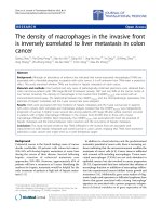
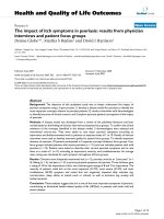
Figure 1 shows the scanning electron microscopy (SEM)
images after KrF lithography and O
2
plasma ashing. As
explained in the experimental details, 160-nm silicon pat-
terns are defined photo-lithographically defined by using
KrF scanner as shown in Fig. 1a. And by using O
2
plasma
ashing technique, 160-nm patterns are reduced down to
30 nm as shown Fig. 1b. By using this technique, bunches
of silicon nanowires can be patterned on the whole region
of 8-inch wafer.
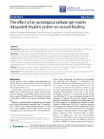
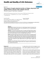
Figure 2 shows the finally formed silicon nanowire
pattern after the removal of 2 lm-thick BOX layer using
gas phase etching (GPE) using HF vapor gas. As shown in
Fig. 2, the 30 nm-wide silicon nanowire is fully suspended.
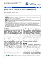
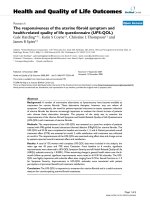
The variations of electrical conductivities of n-/p-legs as
a function of nanowire width are summarized in Fig. 3.
The open and closed circles correspond to n-/p-leg,
respectively. N-leg is doped using phosphorus with the
dose of 5 9 10
15
cm
-2
. The extracted electrical conduc-
tivity of 30-nm n-leg (r
n
) is 842 X
-1
cm
-1
, and the
corresponding doping concentration is around 6.0 9
10
19
cm
-3
. P-leg is doped using BF
2
with the dose of
5 9 10
15
cm
-2
. The extracted electrical conductivity of
30 nm p-leg (r
p
) is 396 X
-1
cm
-1
, and the corresponding
doping concentration is around 4.0 9 10
19
cm
-3
[11]. The
Fig. 1 SEM images after KrF
lithography (a) and O
2
plasma
ashing (b)
Fig. 2 SEM image of the finally formed silicon nanowire after the
removal of 2 lm-thick BOX layer using GPE method
10 100 1000
0
500
1000
1500
2000
σ
(ohm
-1
cm
-1
)
Silicon nanowire width (nm)
N-leg
P-leg
Fig. 3 The variations of electrical conductivities as a function of
nanowire width in n-/p-legs. The open and closed circles correspond
to n-leg and p-leg, respectively. N-leg is doped using phosphorus with
the dose of 5 9 10
15
cm
-2
. P-leg is doped using BF
2
with the dose of
5 9 10
15
cm
-2
Nanoscale Res Lett (2010) 5:1654–1657 1655
123
decrease in electrical conductivities with the decrease in
width is due to the finite line width effect.
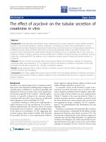
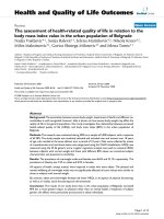
Figure 4 shows the measured output voltage as a func-
tion of temperature difference between cold and hot region.
The cold region temperature (T
C
) is set as 20°C, and the hot
region temperature (T
H
) is controlled from 20 to 42°C. The
output voltage characteristics are measured in various
nanowire widths of 30, 40, 100 and 150 nm. The output
voltage linearly increases as the temperature increases
in both n-/p-leg. The slope represents Seebeck coefficient.
P-leg shows more sensitive response to the temperature
than n-leg, which is typical characteristic in thermoelectric
material [13].
Figure 5 shows the extracted Seebeck coefficients from
Fig. 4. The open and closed circles correspond to n-leg and
p-leg, respectively. In n-leg, Seebeck coefficient (a
n
) varies
from -77 to -94 lV/K depending on the width. In p-leg,
Seebeck coefficient (a
p
) varies from 108 to 122 lV/K. In
the case of serial connection between n-leg and p-leg, the
attainable Seebeck coefficient value (a) can be estimated
using weighted average relation, i.e., a = (a
n
r
n
? a
p
r
p
)/
(r
n
? a
p
)[2]. By applying this relation, the maximum
attainable Seebeck coefficient is 105 lV/K in the case of
serial connection between 30-nm n-leg and 40-nm p-leg. In
this case, the maximum attainable power factor (a
2
Ár)is
0.74 mW K
-2
cm
-1
. By optimizing the doping concen-
tration, nanowire width and process conditions, Seebeck
coefficient should be increased up to 200 lV/K for the
comparable property with Bi
2
Te
3
in power factor.
Conclusions
CMOS compatible process is adopted to implement the real
silicon thermoelectric device. By using conventional
CMOS process, we have manufactured n-/p-type silicon
nanowires. The defined minimum width of silicon nanowire
is 30 nm. The electrical conductivities of n-/p-leg nano-
wires are extracted with the variation of width. Using this
structure, Seebeck coefficients are measured. The obtained
maximum Seebeck coefficient values are 122 lV/K for
p-leg and -94 lV/K for n-leg, respectively. The maxi-
mum attainable power factor is 0.74 mW/m K
2
at room
temperature.
Open Access This article is distributed under the terms of the
Creative Commons Attribution Noncommercial License which per-
mits any noncommercial use, distribution, and reproduction in any
medium, provided the original author(s) and source are credited.
0.0
-0.5
-1.0
-1.5
-2.0
: 30 nm
: 40 nm
: 100 nm
: 150 nm
N-leg
TE voltage (mV)
Temperature (
°
C)
Temperature (
°
C)
20 25 30 35 40
0.0
0.5
1.0
1.5
2.0
2.5
P-leg
: 30 nm
: 40 nm
: 100 nm
: 150 nm
TE voltage (mV)
20 25
30 35
40
(a)
(b)
Fig. 4 The measured output voltage as a function of temperature
difference between cold and hot region. The cold region temperature
(T
C
) is set as 20°C, and the hot region temperature (T
H
) is controlled
from 20 to 42°C. The output voltage characteristics are measured in
various nanowire widths of 30, 40, 100 and 150 nm
50 100 150
60
80
100
120
140
Seebeck coefficient (μV/K)
Silicon nanowire width (nm)
N-leg
P-leg
Fig. 5 The extracted Seebeck coefficients with the variation of
nanowire width. The open and closed circles correspond to n-leg and
p-leg, respectively
1656 Nanoscale Res Lett (2010) 5:1654–1657
123
References
1. D.M. Rowe, Thermoelectrics Handbook (CRC, Boca Raton,
2006)
2. T.M. Tritt, M.A. Subramanian, MRS Bull. 31, 188 (2006)
3. G.J. Snyder, E.S. Toberer, Nat. Mater. 7, 105 (2008)
4. T.C. Harman, P.J. Tayor, M.P. Walsh, B.E. LaForge, Science
297, 2229 (2002)
5. R. Venkatasubramanian, E. Siivola, T. Colpitts, R. O’Quinn,
Nature 413, 597 (2001)
6. B. Yang, J.L. Liu, K.L. Wang, G. Chen, Appl. Phys. Lett. 80,
1758 (2002)
7. C.N. Liao, C. Chen, K.N. Tu, J. Appl. Phys. 86, 3204 (1999)
8. A.I. Bouaki, Y. Bunimovich, J. Tahir-Kheli, J. Yu, W.A. Goddard
III, J.R. Heath, Nature 451, 168 (2008)
9. A.I. Hochbaum, R. Chen, R.D. Delgado, W. Liang, E.C. Garnett,
M. Najarian, A. Majumdar, P. Yang, Nature 451, 163 (2008)
10. D. Li, Y. Wu, R. Fan, P. Yang, A. Majumdar, Appl. Phys. Lett.
83, 3186 (2003)
11. S.M. Sze, Physics of Semiconductor Devices (Wiley, New York,
1981), pp. 27–35
Nanoscale Res Lett (2010) 5:1654–1657 1657
123