Báo cáo hóa học: " Growth of Inclined GaAs Nanowires by Molecular Beam Epitaxy: Theory and Experiment" docx
Bạn đang xem bản rút gọn của tài liệu. Xem và tải ngay bản đầy đủ của tài liệu tại đây (369.1 KB, 6 trang )
NANO EXPRESS
Growth of Inclined GaAs Nanowires by Molecular Beam Epitaxy:
Theory and Experiment
X. Zhang
•
V. G. Dubrovskii
•
N. V. Sibirev
•
G. E. Cirlin
•
C. Sartel
•
M. Tchernycheva
•
J. C. Harmand
•
F. Glas
Received: 2 June 2010 / Accepted: 2 July 2010 /Published online: 24 July 2010
Ó The Author(s) 2010. This article is published with open access at Springerlink.com
Abstract The growth of inclined GaAs nanowires (NWs)
during molecular beam epitaxy (MBE) on the rotating
substrates is studied. The growth model provides explicitly
the NW length as a function of radius, supersaturations,
diffusion lengths and the tilt angle. Growth experiments are
carried out on the GaAs(211)A and GaAs(111)B substrates.
It is found that 20° inclined NWs are two times longer in
average, which is explained by a larger impingement rate
on their sidewalls. We find that the effective diffusion
length at 550°C amounts to 12 nm for the surface adatoms
and is more than 5,000 nm for the sidewall adatoms.
Supersaturations of surface and sidewall adatoms are also
estimated. The obtained results show the importance of
sidewall adatoms in the MBE growth of NWs, neglected in
a number of earlier studies.
Keywords Inclined GaAs nanowires Á
Molecular beam epitaxy Á Surface diffusion
Introduction
A rapidly growing interest in self-standing NWs of III–V
compound semiconductors is explained by an interesting
physics of their growth [1–6], crystal structure [6, 7]
transport [8] and optical [9] phenomena as well as a variety
of promising applications in nanoelectronics [8] and
nanophotonics [9, 10]. III–V NWs with radii of the order of
10 nm and length up to ten micrometers are usually fab-
ricated by metal organic chemical vapor deposition
(MOCVD) [1, 2] or MBE [3–7] via the so-called vapor–
liquid–solid (VLS) mechanism [11] on the substrates
activated by a metal (Au) growth catalyst. Due to their
ability to accommodate strain in two dimensions, NWs are
ideal candidates for monolithic integration of dissimilar
semiconductor materials, e.g., of III–V compounds on Si
[12, 13]. For the controlled production of NWs with the
desired morphology and crystal structure, it is important to
understand major kinetic processes driving NW growth at
given set of deposition conditions. Furthermore, theoretical
and experimental investigations into NW formation
mechanisms can provide important information on many
kinetic characteristics (e.g., supersaturations, diffusion
lengths and surface energies [1–5, 14–22]) that are other-
wise not easy to measure or even define theoretically.
Since the dominant growth direction of NWs is 111
hi
,
most growth experiments [1–6] are carried out on the (111)
oriented surfaces, with NWs being perpendicular to the
substrate. As regards the growth mechanisms of such NWs,
semiconductor material is transferred to the drop (seated at
the NW top) by different kinetic pathways: the direct
X. Zhang
Key Laboratory of Information Photonics and Optical
Communications (Ministry of Education), Beijing University of
Posts and Telecommunications, P.O. Box 66, 100876 Beijing,
China
X. Zhang Á V. G. Dubrovskii Á N. V. Sibirev Á G. E. Cirlin
St Petersburg Academic University RAS, Khlopina 8/3, 194021
St Petersburg, Russia
V. G. Dubrovskii (&) Á G. E. Cirlin
Ioffe Physical-Technical Institute RAS, Politekhnicheskaya 26,
194021, St Petersburg, Russia
e-mail:
G. E. Cirlin Á C. Sartel Á J. C. Harmand Á F. Glas
CNRS-LPN, Route de Nozay, 91460 Marcoussis, France
M. Tchernycheva
Department OptoGaN, Institut d’Electronique Fondamentale,
UMR 8622 CNRS, 91405 Orsay Cedex, France
123
Nanoscale Res Lett (2010) 5:1692–1697
DOI 10.1007/s11671-010-9698-7
impingement onto the drop surface and the surface diffu-
sion of adatoms that first impinge the sidewalls and sub-
strate [1–6, 14–22]. The diffusion-induced contribution
into the overall growth rate is always dominant in MBE
[3–6, 14, 22]. For very thin NWs, it is important to consider
the Gibbs–Thomson (GT) effect of elevation of chemical
potential caused by the curvature of the drop surface
[2, 15]. In MBE case, the flux directly impinging the
sidewalls increases with the incident angle of the beam.
The use of substrate orientation other than (111), resulting
in the formation of inclined NWs with varying tilt angle
(and consequently the incident angle of the beam), can
therefore provide an additional parameter to alter the NW
morphology. The incident angle of the flux impinging the
tilted NW is, however, changing in time if the substrate is
rotating, so a proper averaging should be introduced to
generalize the existing models. The use of high-index
substrates, implemented earlier, e.g., for the growth of
InGaAs/GaAs quantum wells [23], can be of particular
importance in connection with the phase perfection: as
demonstrated in Refs. [7, 24], the use of particular high-
index GaAs substrates for the Au-seeded MBE growth of
GaAs NWs produces stacking fault-free zincblende
structure.
In this work, we report on theoretical and experimental
investigation into the Au-assisted MBE of inclined GaAs
NWs. A theoretical model of Refs. [6, 15] is developed to
describe the growth of inclined NWs and to find explicitly
the dependence of NW growth rate as a function of tilt
angle at given set of deposition conditions. We then carry
out MBE growth experiments on the GaAs(211)A and
GaAs(111)B substrates. From the analysis of scanning
electron microscopy (SEM) images of different samples,
we plot the length-radius curves and fit them by theoretical
dependences. This enables to deduce some important
kinetic parameters of NW growth, in particular, the effec-
tive supersaturations and diffusion lengths on different
GaAs surfaces.
Theoretical Model
The model of inclined NW is sketched in Fig. 1.We
consider a single NW growing in a stationary mode in
z direction making the tilt angle u to the substrate normal.
Neither lateral growth nor shadowing effect is taken into
account. The model parameters include the impingement
flux J, the incident angle of molecular beam a (in the case
of III–V compounds, the growth rate is assumed as being
limited by the incorporation of group III element so that a
relates to the group III beam), the contact angle of the drop
b and the drop surface energy c. Under the standard
assumption of a low concentration of group V element (As)
in the drop [2, 4, 25], the value of c must be between the
surface energy of pure liquid group III element (Ga) and
Au at the growth temperature T. Effective diffusion lengths
on the substrate and sidewalls, limited either by desorption
or incorporation to a growing surface layer [25
], are
denoted as k
s
and k
f
, respectively. The quantities h
v
, h
s
, h
f
and h
l
denote the activities (the effective supersaturations)
of group III element in the vapor (v), surface adatom (s),
sidewall adatom (f) and liquid (l) phases, with the usual
definition of h
i
= exp(l
i
/k
B
T), where l
i
is the chemical
potential in phase i (measured, e.g., with respect to the
solid phase) and k
B
is the Boltzmann constant [6].
The sidewall impingement rate must be corrected for the
effective incident angle of the beam to the inclined NW.
Below we consider the general case of rotating substrate,
schematized in Fig. 2. The NW growth direction is given
by the radius vector n
~
¼ðsin / cos w; sin / sin w; cos /Þ;
while the direction of the flux is parallel to the vector k
~
¼
ð0; sin a; cos aÞ: For the incident angle of the beam to the
NWn, this yields:
Fig. 1 Illustration of the growth model with the parameters
described in the text
Fig. 2 Direction k
~
parallel to the flux and the momentum growth
direction of NW n
~
at time t (with respect to stationary coordinates
x and y) defined by the tilt angle / and the angle w = xt, with x as
the angular velocity of substrate rotation
Nanoscale Res Lett (2010) 5:1692–1697 1693
123
cos n ¼ sin a sin usin w þ cos a cos u: ð1Þ
The activities of adatom phases [6, 15] can be now put
in the form
h
s
¼ Js
s
r
s
cos a; h
f
¼ Js
f
r
f
sin n
hi
: ð2Þ
Here, r
s
, r
f
are the elementary areas of substrate and
sidewall surfaces, and s
s
, s
f
are the corresponding adatom
lifetimes. The quantity sin nhidenotes the mean value of
sinn averaged over the substrate revolution. Obviously,
sin n
hi
¼
1
2p
Z
2p
0
dn
ffiffiffiffiffiffiffiffiffiffiffiffiffiffiffiffiffiffiffiffi
1 Àcos
2
n
p
; ð3Þ
where cosn is given by Eq. 1. Our numerical analysis shows
that Eq. 3 can be well approximated (with less than 7% error)
by the simplified formula sin n
hi
ffi
ffiffiffiffiffiffiffiffiffiffiffiffiffiffiffiffiffiffiffiffiffiffiffiffi
1 À cos
2
n
hi
p
; where,
in view of Eq. 1, cos
2
n
¼ cos
2
a cos
2
u þð1=2Þsin
2
a
sin
2
u: With this approximation, we get
sin n
hi
ffi
ffiffiffiffiffiffiffiffiffiffiffiffiffiffiffiffiffiffiffiffiffiffiffiffiffiffiffiffiffiffiffiffiffiffiffiffiffiffiffiffiffiffiffiffiffiffiffiffiffiffiffiffiffiffiffiffiffiffiffiffiffiffiffiffiffi
1 Àcos
2
a cos
2
u À
1
2
sin
2
a sin
2
u
r
; ð4Þ
the expression used hereinafter for the effective incident
angle to the inclined NWs. Obviously, Eq. 4 [as well as
general Eqs. 1 and 3] is reduced to trivial identity sin n
hi
¼
sin a at u = 0, i.e., the growth of straight NWs is not
influenced by the substrate rotation.
The detailed analysis of Refs. [6, 15] shows that the
exact solution for the stationary NW growth rate has the
form
dL
dH
¼ A þ
BUðL=k
f
ÞþC
U
0
ðL=k
f
Þ
: ð5Þ
Here, L is the NW length, H = Vt is the effective
deposition thickness at time t, V = JX
s
cosa is the
deposition rate (with X
s
as the elementary volume in the
solid phase) and k
f
¼
ffiffiffiffiffiffiffiffiffi
D
f
s
f
p
is the effective diffusion
length on the sidewalls (with D
f
as the corresponding
diffusion coefficient). The A term describes the direct
impingement onto the drop surface [26], the desorption
from the drop and the growth of surface layer. Since in our
experiments the inequality b [ p/2 ? n [26] holds for
most n during the substrate rotation, the corresponding
averaging is almost independent on the incident angle n:
A ¼
1
cos a sin
2
b
1 À2ð1 Àcos bÞ
expðR
GT
=RÞ
h
vl
!
À e: ð6Þ
The desorption term contains the standard GT
modification of liquid activity h
l
[2, 6], with R
GT
=
(2cX
l
sinb)/(k
B
T) as the characteristic GT radius and X
l
as
the elementary liquid volume. The desorption rate is
inversely proportional to the ratio of activities in the vapor
and infinitely large liquid alloy, h
vl
h
v
=h
1
l
: The quantity
e = V
s
/V accounts for the substrate growth, with V
s
as the
growth rate on the non-activated surface [3].
The second, L-dependent term in the right hand side of
Eq. 5 gives two diffusion-induced contributions, one
originating from the adatoms impinging the sidewalls and
migrating to the drop and another caused by the adatoms
that first impinge the substrate and then diffuse to the drop
along the sidewalls. The coefficients B (describing the
sidewall adatoms) and C (describing the substrate adatoms)
in the case of MBE are given by [6]
B ¼
2k
f
pR
sin n
hi
cos a
1 À
expðR
GT
=RÞ
h
fl
!
;
C ¼
2k
s
R
dðR=k
s
Þ 1 À
expðR
GT
=RÞ
h
sl
!
: ð7Þ
Here, h
fl
h
f
=h
1
l
and h
sl
h
s
=h
1
l
are the effective
supersaturations of sidewall and surface adatoms with
respect to the infinite liquid alloy, d(R/k
s
) = K
1
(R/k
s
)/
K
0
(R/k
s
), k
s
¼
ffiffiffiffiffiffiffiffiffi
D
s
s
s
p
is the effective diffusion length on
the substrate surface (with D
s
as the corresponding
diffusion coefficient) and K
n
(x) are the modified Bessel
function of the second kind of order n. Further, the
functions U(L/k
f
) and U
0
(L/k
f
)inEq.5 are defined as
follows
Uð L= k
f
Þ¼sinhðL=k
f
ÞþmdðR=k
s
Þ coshðL=k
f
ÞÀ1
ÂÃ
;
U
0
ðL=k
f
ÞdU=dðL=k
f
Þ¼coshðL=k
f
ÞþmdðR=k
s
ÞsinhðL= k
f
Þ
ð8Þ
with
m
D
s
r
f
k
f
D
f
r
s
k
s
¼
pk
s
k
f
h
fl
h
sl
cos a
sin nhi
: ð9Þ
At given MBE growth conditions (T, V, a, V/III fluxes
ratio), the vapor–solid chemical potential and consequently
the vapor supersaturation is well defined [25], but it
generally tells nothing about the quantity h
vl
entering Eq. 6
for A. If, however, the growth temperature is low enough,
we can safely neglect the desorption term in Eq. 6 (perhaps
excluding very thin NWs) and eliminate unknown h
vl
.In
this case, with the known material constants (providing the
GT radius R
GT
), contact angle b and tilt angle /, the
measured L(H)orL(R) curves of inclined NWs can be
fitted by four parameters, two diffusion lengths k
s
, k
f
and
two supersaturations h
fl
, h
sl
.AtL/k
f
( 1 and k
s
/k
f
( 1,
the dependence on k
f
disappears. The non-vanishing terms
at L/k
f
? 0 and k
s
/k
f
? 0 (yielding also s
s
/s
f
? 0) reduce
Eqs. 5, 8, 9 to the non-linear growth equation of the form
[27]
dL
dH
¼
a
0
þ a
1
L=k
s
þ a
2
ðL=k
s
Þ
2
1 þbdðR=k
s
ÞL=k
s
ð10Þ
with coefficients
1694 Nanoscale Res Lett (2010) 5:1692–1697
123
a
0
¼ A þ C; a
1
¼ AbdðR=k
s
Þþðk
s
=k
f
ÞB;
a
2
¼ðk
s
=2k
f
ÞBbdðR=k
s
Þ; b ¼
D
s
r
f
D
f
r
s
: ð11Þ
Thus, our model provides the exact solution for the NW
growth rate with the tilt angle as the control parameter.
This solution contains, however, a number of unidentified
quantities that can be found only from the direct
comparison with experiment.
Growth Experiments
Our growth experiments were carried out with a Riber 32
MBE setup equipped with solid sources supplying mono-
mers of Ga and tetramers of As
4
. Growth was performed on
the GaAs (111)B and GaAs(211)A substrates. During the
growth, the substrates rotation was applied. Incident angle
of Ga flux a amounted to 16.7° to the normal. Substrate
surfaces were deoxidized at 620°C, and a 30 nm GaAs
buffer layers were grown to achieve atomically flat surface.
Then, the substrate temperature was decreased and stabi-
lized to T = 550°C for the NW growth on the both types of
substrates. For catalyst deposition, Au source installed
directly into the growth chamber in a regular effusion cell
was used. This configuration enables to deposit the catalyst
on chemically clean surface, and at the same time to con-
trol the substrate temperature and monitor the deposition
process with reflection high-energy electron diffraction. An
amount of Au equivalent to a uniform layer of *1 nm was
deposited on the substrate surface to promote the NW
growth. This procedure resulted in the formation of Au
droplets alloyed with the substrate constituents which
could activate the NW growth. Since the growth temper-
ature of 550°C is much higher than the lowest eutectic
temperatures of Au–Ga alloy (339.4°C and 348.9°C[28]),
the drop must remain liquid during the growth. For all
samples, the nominal growth rate V was fixed to 0.2 nm/s,
the V/III flux ratio was equal 3 and the effective deposition
thickness was fixed to 360 nm with the corresponding
deposition time of 30 min.
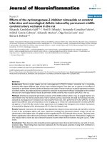
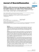
The morphology of as-grown GaAs NW ensembles was
investigated using field-emission SEM technique. Fig-
ures 3 and 4 present typical SEM images of GaAs NWs
grown on the GaAs(111)B and GaAs(211)A substrates,
respectively, under identical deposition conditions descri-
bed hereinabove. It is seen that all NWs have almost uni-
form radius from base to top, which agrees with the results
of Ref. [29] where the pronounced lateral growth [18, 19]
was observed only below 500°C. This justifies the
assumption of NW elongation at R = const. As expected,
the NWs grown on the (111)B substrate are perpendicular
to the surface. From the analysis of plan and top view SEM
images, the tilt angle of NWs on the (211)A substrate
varies from 15 to 30°, with the statistical average around
20°, which equals the angle between the (211) plane
and 111
hi
crystallographic direction. This confirms the
dominant 111higrowth direction of inclined NWs. The
measured lengths of selected NWs and the average thick-
ness of surface layer on the non-activated substrates are
shown in the figures. Statistical analysis of SEM images
presented in Figs. 3 and 4 enables to plot out the length-
radius dependences shown by points in Fig. 5.
Results and Discussion
From Fig. 5, the length of all NWs is noticeably larger than
the deposition thickness (360 nm), and is almost 6 times
Fig. 3 Cross-view SEM image of straight GaAs NWs on the
GaAs(111)B substrate
Fig. 4 Cross-view SEM image of inclined GaAs NWs on the
GaAs(211)A substrate. Average tilt angle equals 20°, average
thickness of surface layer is 357 nm, with the initial buffer layer
thickness of 30 nm
Nanoscale Res Lett (2010) 5:1692–1697 1695
123
larger for longest 2 lm NWs, which proves the diffusion-
induced character of NW growth discussed previously in
Ref. [1–6, 14–22]. The solid lines in Fig. 5 are obtained
from general expressions given by Eqs. 2, 4, 5–9 with the
parameters summarized in Table 1. The dotted lines cor-
respond to simplified Eqs. 10 and 11 with the same fitting
parameters. According to the data of Ref. [25], the vapor
supersaturation h
v
= exp (Dl
v
/k
B
T) with respect to the
GaAs(111)B substrate equals approximately 183 at
T = 550°C,, so that the assumption of h
vl
? ? (i.e.,
negligible re-evaporation from the drop) looks reasonable.
At T = 550°C, the average contact angle of the drops
b = 120° and c = 1.0 J/m
2
(corresponding to approxi-
mately 40% Ga concentration in the liquid Au–Ga alloy
during the growth [15]), the GT radius R
GT
equals 5.8 nm.
With neglect of desorption, the value of e in Eq. 6 is
estimated as e % H
s
/H = 327/360 = 0.91, i.e. only 9% of
material is distributed in the NWs and 91% remains in a 2D
surface layer growing concomitantly with the NWs. As
follows from Fig. 5, the simplified growth equation at
L/k
f
? 0 is a good approximation to the general expres-
sions for the parameters considered. A small difference
which can be seen for the longest NWs with L [2 lmis
explained by the re-evaporation of some Ga adatoms from
the sidewalls. Due to this desorption, the actual length
becomes smaller than that predicted by the simplified
formula where the re-evaporation is neglected. As in Refs.
[2, 15, 25], theoretical model predicts the non-monotonous
behavior of the L(R) curves, reaching their maxima due to the
balance of the GT and the diffusion-induced contributions
into the overall growth rate. The GT effect suppresses
completely the growth of straight GaAs with R \ 9 nm and
inclined GaAs NWs with R \ 15 nm. The obtained estimate
of minimum radius for the straight GaAs NWs is consistent
with the result of Ref. [2] in the case of Au-catalyzed
MOCVD of straight InAs NWs (*8nmatT = 425°C).
As follows from the results summarized in Table 1, the
effective diffusion length on the substrate surfaces (limited
by the incorporation into a growing surface layer) appears
to be only 12 nm for the both substrates studied. This
estimate is noticeably smaller than the previously obtained
results of 25 nm (Ref. [22]) and 35 nm (Ref. [14]) at
560°C. Such difference is most probably explained by the
simplified growth equation used in Ref. [14, 22], i.e.,
dL/dH = a
0
instead of Eq. 10, resulting in the neglect of
sidewall adatoms. It is noteworthy that the non-linear terms
in L/k
s
in Eqs. 10, 11 contain the contributions from
sidewall adatoms through the k
f
-independent coefficients
(k
s
/k
f
)B in the corresponding Eqs. 11 for a
1
and a
2
. These
contributions cancel exactly only at B = 0, i.e., for straight
NWs (/ = 0) and the beam being strictly perpendicular to
the substrate (a = 0). Otherwise, the diffusion of adatoms
directly impinging the NW sidewalls plays an important
role even at the initial stage of NW growth with L/k
f
( 1,
the effect overlooked in the number of recent studies [2, 14,
22]. Since our NWs are relatively short, the fit obtained
from general expressions given by Eqs. 5–9 becomes
independent on k
f
at k
f
C 5,000 nm. We can therefore
conclude that the effective diffusion length of Ga atoms on
the NW sidewalls (which should be constructed from six
equivalent ð2
"
1
"
1Þ facets in the case of zincblende NWs or
their ð1
"
100Þ wurtzite counterparts [25]) is more than
5,000 nm. This result is consistent with previous estimates,
e.g., 3,000 nm at 590°C in Ref. [4].
As regards the obtained estimates for the effective
supersaturations, the first obvious conclusion is that the
inequalities h
sl
[ 1 and h
fl
[ 1 yield positive (i.e., directed
from base to top) diffusion fluxes at R
GT
/R ( 1 for the
surface and sidewall adatoms, because the adatom chemical
potentials are larger than the chemical potential of infinite
liquid alloy [6]. The corresponding flux becomes negative
only for sufficiently thin NWs due to the GT effect. For the
both cases considered, the supersaturation of sidewall
Fig. 5 Experimental (points) and theoretical (lines) length-radius
dependences of straight (stars) and inclined (open squares) GaAs
NWs. Fits are obtained from exact Eqs. 5–9 [solid lines] and
simplified Eqs. 10 and 11 [dotted lines] with the parameters
summarized in Table 1
Table 1 Growth conditions and fitting parameters for different GaAs NWs
Substrate T (°C) / (deg) k
s
(nm) h
sl
Dl
sl
(meV) k
f
(nm) h
fl
Dl
fl
(meV)
GaAs(111)B 550 0 12 1.67 36.5 5,000 11.2 172
GaAs(211)A 550 20 12 1.40 24.0 5,000 16.3 199
1696 Nanoscale Res Lett (2010) 5:1692–1697
123
adatoms is several times larger than that of surface adatoms,
which is qualitatively consistent with the strong inequality
k
f
/k
s
) 1. The supersaturation of sidewall adatoms is
noticeably larger for the inclined NWs (16.3 against 11.2 for
the straight NWs), which is again explained by a larger
impingement onto the tilted sidewalls. The corresponding
differences in chemical potentials in the adatom and infinite
liquid phases, obtained from the relationships h
sl
= exp
(Dl
sl
/k
B
T); h
fl
= exp (Dl
fl
/k
B
T), equal 24.0–36.5 meV for
the surface and 172–199 meV for the sidewall adatoms.
To sum up, our results show that the diffusion of adatoms
that first impinge the sidewalls has a tremendous effect on the
growth rate. First, since the diffusivity of surface adatoms
during MBE is fundamentally limited by the growing surface
layer, and their supersaturation is much lower than that of the
sidewall adatoms, the coefficient C in Eq. 5 is usually much
smaller than B and even much smaller than A. Therefore, the
initial growth stage should be controlled by the direct
impingement onto the drop surface (A), while the contribu-
tion from the sidewall adatoms (B) rapidly increases as the
NW elongates. Second, our experimental data and theoreti-
cal fits demonstrate that the inclined 111
hi
NWs grow much
faster than the straight ones: from Fig. 4, the GaAs NWs on
the GaAs(211)A substrate are more than 2 times larger at the
same radii and otherwise identical deposition conditions.
Better analysis could be performed with the experimental
length–time dependences, where different contributions at
different growth stages would be more easily distinguished
[30, 31]. As yet, however, we do not have in hand such
experimental data for the inclined GaAs NWs. As the NWs
grow, the shadowing effect might become important at a
certain critical length which can be easily estimated with
given incident angle of the beam and the NW density. We
now plan to consider these effects from the viewpoint of the
obtained results.
Acknowledgments This work was partially supported by the 111
Project (No. B07005), Program for Changjiang Scholars and Inno-
vative Research Team in University (No. IRT0609), National Basic
Research Program of China (No. 2010CB327600), Russian Federal
Agency for Science and Innovation (Contract No. 02.740.11.0383),
the scientific program of Russian Academy of Sciences ‘‘Fundamental
aspects of nanotechnologies and nanomaterials’’ and few grants of
Russian Foundation for Basic Research.
Open Access This article is distributed under the terms of the
Creative Commons Attribution Noncommercial License which per-
mits any noncommercial use, distribution, and reproduction in any
medium, provided the original author(s) and source are credited.
References
1. W. Seifert, M. Borgstrom, K. Deppert, K.A. Dick, J. Johansson,
M.W. Larsson, T. Martensson, N. Skold, C.P.T. Svensson, B.A.
Wacaser, L.R. Wallenberg, L. Samuelson, J. Cryst. Growth 272,
211 (2004)
2. L.E. Fro
¨
berg, W. Seifert, J. Johansson, Phys. Rev. B 76, 153401
(2007)
3. V.G. Dubrovskii, G.E. Cirlin, I.P. Soshnikov, A.A. Tonkikh, N.V.
Sibirev, Yu.B. Samsonenko, V.M. Ustinov, Phys. Rev. B 71,
205325 (2005)
4. J.C. Harmand, G. Patriarche, N. Pe
´
re
´
-Laperne, M N. Me
´
rat-
Combes, L. Travers, F. Glas, Appl. Phys. Lett. 87, 203101 (2005)
5. M.C. Plante, R.R. LaPierre, J. Cryst. Growth 286, 394 (2006)
6. V.G. Dubrovskii, N.V. Sibirev, G.E. Cirlin, A.D. Bouravleuv,
Yu.B. Samsonenko, D.L. Dheeraj, H.L. Zhou, C. Sartel,
J.C. Harmand, G. Patriarche, F. Glas, Phys. Rev. B 80, 066940
(2009)
7. H. Shtrikman, R. Popovitz-Biro, A. Kretinin, M. Heiblum, Nano
Lett. 9, 215 (2009)
8. M.T. Bjork, B.J. Ohlsson, T. Sass, A.I. Persson, C. Thelander,
M.H. Magnusson, K. Deppert, L.R. Wallenberg, L. Samuelson,
Appl. Phys. Lett. 80, 1058 (2002)
9. J. Xiang, W. Lu, Y.J. Hu, Y. Wu, H. Yan, C.M. Lieber, Nature
441, 489 (2006)
10. G.E. Cirlin, A.D. Bouravleuv, I.P. Soshnikov, Yu.B. Sams-
onenko, V.G. Dubrovskii, E.M. Arakcheeva, E.M. Tanklevskaya,
P. Werner, Nanoscale Res. Lett. 5, 360 (2010)
11. R.S. Wagner, W.C. Ellis, Appl. Phys. Lett. 4, 89 (1964)
12. L.C. Chuang, M. Moewe, S.Crankshaw, C. Chase, N.P. Kobayashi,
C. Chang-Hasnain, Appl. Phys. Lett. 90, 043115 (2007)
13. G.E. Cirlin, V.G. Dubrovskii, I.P. Soshnikov, N.V. Sibirev, Yu.B.
Samsonenko, A.D. Bouravleuv, J.C. Harmand, F. Glas, Phys.
Stat. Sol. RRL 3, 112 (2009)
14. V.G. Dubrovskii, N.V. Sibirev, R.A. Suris, G.E. Cirlin,
J.C. Harmand, V.M. Ustinov, Surf. Sci. 601, 4395 (2007)
15. V.G. Dubrovskii, N.V. Sibirev, G.E. Cirlin, I.P. Soshnikov, W.H.
Chen, R. Larde, E. Cadel, P. Pareige, T. Xu, B. Grandidier, J P.
Nys, D. Stievenard, M. Moewe, L.C. Chuang, C. Chang-Hasnain,
Phys. Rev. B 79, 205316 (2009)
16. J. Johansson, C.P.T. Svensson, T. Martensson, L. Samuelson,
W. Seifert, J. Phys. Chem. B 109, 13567 (2005)
17. I. Avramov, Nanoscale Res. Lett. 2, 235 (2007)
18. M.C. Plante, R.R. LaPierre, J. Appl. Phys. 105, 114304 (2009)
19. V.G. Dubrovskii, N.V. Sibirev, G.E. Cirlin, M. Tchernycheva,
J.C. Harmand, V.M. Ustinov, Phys. Rev. E 77, 031606 (2008)
20. S.N. Mohammad, J. Vac. Sci. Technol. 28, 329 (2010)
21. E. De Jong, R.R. LaPierre, J.Z. Wen, Nanotechnology 21, 045602
(2010)
22. V.G. Dubrovskii, N.V. Sibirev, R.A. Suris, G.E. Cirlin,
V.M. Ustinov, M. Tchernysheva, J.C. Harmand, Semiconductors
40, 1075 (2006)
23. Z. Li, J. Wu, Z.M. Wang, D. Fan, A. Guo, S. Li, S Q. Yu,
O. Manasreh, G.J. Salamo, Nanoscale Res. Lett. 5, 1079 (2010)
24. H. Shtrikman, R. Popovitz-Biro, A. Kretinin, L. Houben,
M. Heiblum, M. Bukala, M. Galicka, R. Buczko, P. Kacman,
Nano Lett. 9, 1506 (2009)
25. V.G. Dubrovskii, N.V. Sibirev, J.C. Harmand, F. Glas, Phys. Rev.
B 78, 235301 (2008)
26. F. Glas, Phys. Stat. Sol. B 247, 254 (2010)
27. V.G. Dubrovskii, N.V. Sibirev, M.A. Timofeeva, Semiconductors
43, 1226 (2009)
28. T.B. Massalski (ed.), Binary alloy phase diagrams, vol. 1, 1st
edn. (American Society for Metals, Metals Park, OH, 1986),
p. 260
29. J.C. Harmand, M. Tchernycheva, G. Patriarche, L. Travers,
F. Glas, G. Cirlin, J. Cryst. Growth 301–302, 853 (2007)
30. M. Tchernycheva, L. Travers, G. Patriarche, F. Glas, J.C. Har-
mand, G.E. Cirlin, V.G. Dubrovskii, J. Appl. Phys. 102, 094313
(2007)
31. F. Glas, J.C. Harmand, G. Patriarche, Phys. Rev. Lett. 104,
135501 (2010)
Nanoscale Res Lett (2010) 5:1692–1697 1697
123
![Báo cáo khoa học: Investigation of the interaction between the atypical agonist c[YpwFG] and MOR docx](https://media.store123doc.com/images/document/14/rc/ht/medium_57MlXT7HZ5.jpg)