Báo cáo hóa học: " Review Article Reversible Watermarking Techniques: An Overview and a Classification" doc
Bạn đang xem bản rút gọn của tài liệu. Xem và tải ngay bản đầy đủ của tài liệu tại đây (1.1 MB, 19 trang )
Hindawi Publishing Corporation
EURASIP Journal on Information Security
Volume 2010, Article ID 134546, 19 pages
doi:10.1155/2010/134546
Review A rticle
Reversible Watermarking Techniques:
An Overview and a Classification
Roberto Caldelli, Francesco Filippini, and Rudy Becarelli
MICC, University of Florence, Viale Morgagni 65, 50134 Florence, Italy
Correspondence should be addressed to Roberto Caldelli, roberto.caldelli@unifi.it
Received 23 December 2009; Accepted 17 May 2010
Academic Editor: Jiwu W. Huang
Copyright © 2010 Roberto Caldelli et al. This is an open access article distributed under the Creative Commons Attribution
License, which permits unrestricted use, distribution, and reproduction in any medium, provided the original work is properly
cited.
An overview of reversible watermarking techniques appeared in literature during the last five years approximately is presented
in this paper. In addition to this a general classification of algorithms on the basis of their characteristics and of the embedding
domain is given in order to provide a structured presentation simply accessible for an interested reader. Algorithms are set in a
category and discussed trying to supply the main information regarding embedding and decoding procedures. Basic considerations
on achieved results are made as well.
1. Introduction
Digital watermarking techniques have been indicated so far
as a possible solution when, in a specific application scenario
(authentication, copyright protection, fingerprinting, etc.),
there is the need to embed an informative message in a
digital document in an imperceptible way. Such a goal
is basically achieved by performing a slight modification
to the original data trying to, at the same time, satisfy
other bindings such as capacity and robustness. What is
important to highlight, beyond the way all these issues are
achieved, it is that this “slight modification” is irreversible:
the watermarked content is different from the original
one. This means that any successive assertion, usage, and
evaluation must happen on a, though weakly, corrupted
version, if original data have not been stored and are not
readily available. It is now clear that in dependence of
the application scenario, this cannot always be acceptable.
Usually when dealing with sensitive imagery such as deep
space exploration, military investigation, and recognition,
and medical diagnosis, the end-user cannot tolerate to risk
to get a distorted information from what he is watching
at. One example above all: a radiologist who is checking
a radiographic image to establish if a certain pathology is
present or not. It cannot be accepted that his diagnosis is
wrong both, firstly, to safeguard the patient’s health and,
secondly, to protect the work of the radiolog ist himself.
In such cases, irreversible watermarking algorithms clearly
appear not to be feasible; due to this strict requirement,
another category of watermarking techniques have been
introduced in literature which are catalogued as reversible,
where, with this term, it is to be intended that the original
content, other than the watermark signal, is recovered from
the watermarked document such that any evaluation can
be performed on the unmodified data. Thus doing, the
watermarking process is zero-impact but allows, at the same
time, to convey an informative message.
Reversible watermarking techniques are also named as
invertible or lossless and were born to be applied mainly in
scenarios where the authenticity of a digital image has to
be granted and the original content is peremptorily needed
at the decoding side. It is important to point out that,
initially, a high perceptual quality of the watermarked image
was not a requirement due to the fact that the original
one was recoverable and simple problems of overflow and
underflow caused by the watermarking process were not
taken into account too. Successively also, this aspect has been
considered as basic to p ermit to the end user to operate on
the watermarked image and to possibly decide to resort to
the uncorrupted version in a second time if needed.
2 EURASIP Journal on Information Security
Semi-fragile
Robust
Fragile
Reve rsi ble
Figure 1: Categorization of reversible watermarking techniques.
Reversible algorithms can be subdivided into two main
categories, as evidenced in Figure 1: fragile and semifragile.
Most of the developed techniques belong to the family of
fragile that means that the inserted watermark disappears
when a modification has occurred to the watermarked image,
thus revealing that data integrity has been compromised.
An inferior number, in percentage, are grouped in the
second category of semi-fragile where with this term it is
intended that the watermark is able to survive to a possible
unintentional process the image may undergo, for instance,
a slight JPEG compression.
Such feature could be interesting in applications where
a certain degree of lossy compression has to be tolerated;
that is, the image has to be declared as authentic even if
slightly compressed. Within this last category can also be
included a restricted set of techniques that can be defined as
robust which are able to cope with intentional attacks such as
filtering, partial cropping, JPEG compression with relatively
low quality factors, and so on.
The rationale behind this paper is to provide an overview,
as complete as possible, and a classification of reversible
watermarking techniques, while trying to focus on their
main features in a manner to provide to the readers basic
information to understand if a certain algorithm matches
with what they were looking for. In particular, our attention
has been dedicated to papers appeared approximately from
years 2004-2005 till 2008-2009; in fact, due to the huge
amount of works in this field, we have decided to restrict
our watch to the last important techniques. Anyway we
could not forget some “old” techniques that are consid-
ered as reference throughout the paper, such as [1–3],
though they are not discussed in detail. The paper tries
to categorize these techniques according to the classifi-
cation pictured in Figure 1 and by adding an interesting
distinction regarding the embedding domain they work on:
spatial domain (pixel) or transformed domain (DFT, DWT,
etc.).
The paper is structured as follows: in Section 2,fragile
algorithms are introduced and subdivided into two sub-
classes on the basis of the adopted domain; in Section 3,
techniques which provide features of semi-fragileness and/or
robustness are presented and classified again according to the
watermarking domain. Section 4 concludes the paper.
2. Fragile Algorithms
Fragile algorithms cover the majority of the published
works in the field of reversible. With the term fragile a
watermarking technique which embeds a code in an image
that is not readable anymore if the content is altered.
Consequently the original data are not recoverable too.
2.1. Spatial Domain. This subsection is dedicated to present
some of the main works implementing fragile reversible
watermarking by operating in the spatial domain.
One of the most important works in such a field has
been presented by Tian [4, 5]. It presents a high-capacity,
high visual quality, and reversible data embedding method
for grayscale digital images. This method calculates the
difference of neighboring pixel values and then selects some
of such differences to perform a difference expansion (DE).
In such different values, a payload B made by the following
parts will be embedded:
(i) a JBIG compressed location map,
(ii) the original LSB values, and
(iii) the net authentication payload which contains an
image hash.
To embed the payload, the procedure starts to define two
amounts, the average l and the difference h (see (1)).
Given a pair of pixel values (x, y) in a grayscale image,
with x, y
∈ Z,0≤ x, y ≤ 255,
l
=
x + y
2
h = x − y,(1)
and given l and h, the inverse transform can be respectively
computed according to(2)
x
= l +
h +1
2
; y = l −
h
2
. (2)
The method defines different kinds of pixel couples
according to the characteristics of the corresponding h
and behaves slightly different for each of them during
embedding. Two are the main categories: changeable and
expandable differences, let us see below for their definitions,
respectively.
Definition 1. For a grayscale-valued pair (x, y)adifference
number h is changeable if
2 ×
h
2
+ b
≤
min
(
2
(
255 − l
)
,2l +1
)
.
(3)
Definition 2. For a grayscale-valued pair (x, y)adifference
number h is expandable if
|2 × h + b|≤min
(
2
(
255 − l
)
,2l +1
)
.
(4)
This is imposed to prevent overflow/underflow problems
for the watermarked pixels (x
, y
).
To e m b e d a bi t b
= (0, 1) of the payload, it is necessary
to modify the amount h obtaining h
which is called DE
EURASIP Journal on Information Security 3
Table 1: Payload size versus PSNR of Lena image.
Payload Size (bits) 39566 63676 84066 101089 120619 141493 175984 222042 260018 377869 516794
Bit Rate (bpp) 0.1509 0.2429 0.3207 0.3856 0.4601 0.5398 0.6713 0.8470 0.9919 1.4415 1.9714
PSNR (dB) 44.20 42.86 41.55 40.06 37.66 36.15 34.80 32.54 29.43 23.99 16.47
(Difference Expansion) according to (5) for expandable
differences
h
= 2 × h + b, b = LSB
(
h
)
,
(5)
and (6) for changeable ones
h
= 2 ×
h
2
+ b, b = LSB
(
h
)
,(6)
by replacing h with h
within (2), the watermarked pixel
values x
and y
are got. The basic feature which distinguishes
expandable differences from changeable ones is that the first
ones can carry a bit without asking for saving the original
LSB. That yields to a reduced total payload B.Alocation
map takes into account of the diverse disjoint categories of
differences.
To extract the embedded data and recover the original
values, the decoder uses the same pattern adopted during
embedding and applies (1)toeachpair.Thentwosetsof
differences are created: C for changeable h and NC for not
changeable h. By taking all LSBs of differences belonging to
C set, a bit stream B is created. Firstly, the location map is
recovered and us ed together wi th B to restore the original h
values; secondly, by using (2) the original image is obtained,
lastly, the embedded payload (the remaining part of B)is
used for authentication check by resorting to the embedded
hash.
Tian applies the algorithm to “Lena” (512
× 512), 8 bpp
grayscale image. The experimental results are shown in
Table 1, where the embedded payload size, the corresponding
bitrate, and PSNRs of the watermarked image are listed.
As DE increases, the watermark has the effect similar to
mild sharpening in the mid tone regions. Applying the DE
method on “Lena,” the experimental results show that the
capacity versus distortion is better in comparison with the G-
LSB method proposed in [2], and the RS method proposed
in [1].
The previous method has been taken and extended by
Alattar in [6]. Instead of using difference expansion applied
to pairs of pixels to embed one bit, in this case difference
expansion is computed on spatial and cross-spectral t riplets
of pixels in order to increase hiding capacit y; the algorithm
embeds two bits in each triplet. With the term triplet a
1
× 3 vector containing the pixel values of a colored image
is intended; in particular, there are two kinds of triplets.
(i) Spat ial Triplet: three pixel values of the image chosen
from the same color component within the image
according to a predetermined order.
(ii) Cross-spectral Triplet: three pixel values of the image
chosen from different color components (RGB).
The forward transform for the triplet t
= (u
0
, u
1
, u
2
)is
defined as
v
0
=
u
0
+ wu
1
+ u
2
N
,
v
1
= u
2
− u
1
,
v
2
= u
0
− u
1
,
(7)
where N and w are constant. For spatial triplets, N
= 3and
w
= 1, while in cross-spectral triplets, N = 4andw = 2.
On the other side, the inverse transform, f
−1
(·), for the
transformed triplets t
= (v
0
, v
1
, v
2
)isdefinedas
u
1
= v
0
−
v
1
+ v
2
N
,
u
0
= v
2
+ u
1
,
u
2
= v
1
+ u
1
.
(8)
The value v
1
and v
2
are considered for watermarking
according to (9)
v
1
= 2 × v
1
+ b
1
,
v
2
= 2 × v
2
+ b
2
,
(9)
for all the expandable triplets, where expandable means that
(v
1
+ v
2
) satisfies a limitation similarly to what has been
proposed in the previous paper to avoid overflow/underflow.
In case of only changeable triplets, v
1
= 2 ×v
1
/2 + b
1
(v
2
changes correspondingly), but the same bound for the sum
of these two amounts has to be verified again.
According to the above definition, the algorithm classifies
the triplets in the following groups.
(1) S
1
: contains all expandable triplets whose v
1
≤ T
1
and
v
2
≤ T
2
(T
1
, T
2
predefined threshold).
(2) S
2
: contains all changeable triplets that are not in S
1
.
(3) S
3
: contains the not changeable triplets.
(4) S
4
= S
1
∪ S
2
contains all changeable triplets
In the embedding process, the triplets are transformed using
(7) and then divided into S
1
, S
2
and S
3
. S
1
,andS
2
are
transformed in S
w
1
and S
w
2
(watermarked) and the pixel
values of the original image I(i, j, k) are replaced with the
corresponding watermarked triplets in S
w
1
and S
w
2
to produce
the watermarked image I
w
(i, j,andk). The algorithm uses
a binary JBIG compressed location map M, to identify the
location of the triplets in S
1
, S
2
,andS
3
which becomes part
of the payload together with the LSB of changeable triplets.
In the reading and restoring process, the system simply
follows the inverse steps of the encoding phase. Alattar
4 EURASIP Journal on Information Security
Table 2: Embedded payload size versus PSNR for colored images.
Lena Baboon Fruits
Payload (bits) PSNR (dB) Payload (bits) PSNR (dB) Payload (bits) PSNR (dB)
305,194 35.80 115,050 30.14 299,302 35.36
420,956 34.28 187,248 28.54 497,034 33.00
516,364 33.12 256,334 27.20 582,758 32.45
660,618 31.44 320,070 26.10 737,066 31.14
755,096 30.28 408,840 24.73 824,760 30.06
837,768 29.10 505,150 23.34 853,846 29.49
941,420 27.01 656,456 21.20 888,850 28.52
Table 3: Comparison results between Tian’s and Alattar’s algorithm.
Gray-scale Lena Gray-scale Barbara
Tian’s Alg. Alattar’s Alg. Tian’s Alg. Alattar’s Alg.
PSNR (dB) Payload (bits) Payload (bits) PSNR (dB) Payload (bits) Payload (bits)
29.4 260.018 298.872 23.6 247.629 279.756
32.5 222.042 236.318 31.2 159.000 202.120
34.8 175.984 189.468 32.8 138.621 187.288
36.2 141.493 131.588 34.1 120.997 167.986
37.7 120.619 107.416 37.4 81.219 108.608
40.1 101.089 49.588 40.2 60.577 45.500
41.6 84.066 19.108 42.8 39.941 19.384
w
h
Quad q
= (u
0
, u
1
, u
2
, u
3
)
Figure 2: Quads configuration in an image.
tested the algorithm with three 512 × 512 RGB images, Lena,
Baboon, and Fruits. The algorithm is applied recursively to
columns and rows of each color component. The watermark
is generated by a random binary sequence and T
1
= T
2
in all
experiments. In Ta ble 2, PSNRs of the watermarked images
are shown. In general, the quality level is about 27 dB with a
bitrate of 3.5 bits/colored pixel. In Tabl e 3, it is reported also
the performance comparison in terms of capacity between
the Tian’s algorithm and this one, by using grayscale images
Lena and Barbara.
From the results of Ta ble 3, the algorithm proposed
outperforms the Tian’s technique at lower PSNRs. At higher
PSNRs instead, the Tian’s method outperforms the proposed.
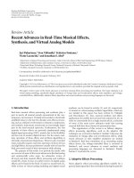
Alattar proposed in [7] an extension of such a technique,
to hide triplets of bits in the difference expansion of quads of
adjacent pixels. With the term quads a1
×4 vector containing
the pixel values (2
× 2 adjacent pixel values) from different
locations within the same color component of the image is
intended (see Figure 2).
The difference expansion transform, f (
·), for the quad
q
= (u
0
, u
1
, u
2
, u
3
)isdefinedasin(10)
v
0
=
a
0
u
0
+ a
1
u
1
+ a
2
u
2
+ a
3
u
3
a
0
+ a
1
+ a
2
+ a
3
,
v
1
= u
1
− u
0
,
v
2
= u
2
− u
1
,
v
3
= u
3
− u
2
.
(10)
The inverse difference expansion transform, f
−
1(·), for
the transformed quad q
= (v
0
, v
1
, v
2
, v
3
) is correspondingly
defined as in (11)
u
0
= v
0
−
(
a
1
+a
2
+a
3
)
v
1
+
(
a
2
+a
3
)
v
2
+a
3
v
3
a
0
+ a
1
+ a
2
+ a
3
,
u
1
= v
1
+ u
0
,
u
2
= v
2
+ u
1
,
u
3
= v
3
+ u
2
.
(11)
Similarly to the approach previously adopted, quads
are categorized in expandable or changeable and differently
treated during watermarking; then they are grouped as
follows.
(1) S
1
: contains all expandable quads whose v
1
≤ T
1
,
v
2
≤ T
2
, v
3
≤ T
3
with v
1
, v
2
, v
3
transformed values
and T
1
, T
2
,andT
3
predefined threshold.
(2) S
2
: contains all changeable quads that are not in S
1
.
(3) S
3
: contains the rest of quads (not changeable).
(4) S
4
: contains all changeable quads (S
4
= S
1
∪ S
2
).
EURASIP Journal on Information Security 5
In the embedding process the quads are transformed by using
(10) and then divided into the sets S
1
, S
2
,andS
3
. S
1
and S
2
are
modified in S
w
1
and S
w
2
(the watermarked versions) and the
pixel values of the original image I(i, j,andk) are replaced
with the corresponding watermarked quads in S
w
1
and S
w
2
to produce the watermarked image I
w
(i, j, k). Watermark
extraction and restoring process proceeds inversely as usual.
In the presented experimental results, the algorithm is
applied to each color component of three 512
× 512 RGB
images, Baboon, Lena, and Fruits setting T
1
= T
2
= T
3
in all experiments. The embedding capacity depends on the
nature of the image itself. In this case, the images with a
lot of low frequencies contents and high correlation, like
Lena and Fruits, produce more expandable triplets with
lower distortion than high frequency images such as Baboon.
In particular with Fruits, the algorithm is able to embed
867 kbits with a PSNR 33.59 dB, but with only 321 kbits
image quality increases at 43.58 dB. It is interesting to verify
that with B aboon the algorithm is able to embed 802 kbits
or 148 kbits achieving a PSNR of 24.73dBandof36.6dB,
respectively.
The proposed method is compared with Tian’s algo-
rithm, using grayscale images, Le na and Barbara.AtPSNR
higher than 35 dB, quad-based technique outperforms Tian,
while at lower PSNR Tian outperforms (marginally) the
proposed techniques. The quad-based algorithm is also com-
pared with [2] method using grayscale images like Lena and
Barbara. Also, in this case the proposed method outperforms
Celik [ 2] at almost all PSNRs. The proposed algorithm is
also compared with the previous work of Alattar described
in [6]. The results reveal that the achievable payload size for
the quad-based algorithm is about 300,000 bits higher than
for the spatial triplets-based algorithm at the same PSNR;
further m ore, the PSNR is about 5 dB higher for the quad-
based algorithm than for the spatial triplet-based algorithm
at the same payload size.
Finally, in [8], Alattar has proposed a further gener-
alization of his algorithm, by using difference expansion
of vectors composed by adjacent pixels. This new method
increases the hiding capacity and the computation efficiency
and allows to embed into the image se veral bits, in every
vector, in a single pass. A vector is defined as u
=
(u
0
, u
1
, , u
N−1
), where N is the number of pixel values
chosen from N different locations within the same color
component, taken, according to a secret key, from a pixel set
of a
× b size.
In this case, the forward difference expansion transform,
f (
·), for the vector u = (u
0
, u
1
, , u
N−1
)isdefinedas
v
0
=
N−1
i=0
a
i
u
i
N−1
i
=0
a
i
,
v
1
= u
1
− u
0
,
.
.
.
v
N−1
= u
N−1
− u
0
,
(12)
where a
i
is a constant integer, 1 ≤ a ≤ h,1≤ b ≤ w and
a + b
/
= 2, (w and h are the image width and height, resp.)
The inverse difference expansion transform, f
−1
(·), for
the transformed vector v
= (v
0
, v
1
, , v
N−1
), is defined as
u
0
= v
0
−
N−1
i=1
a
i
v
i
N−1
i=0
a
i
,
u
1
= v
1
+ u
0
,
.
.
.
u
N−1
= v
N−1
+ u
0
.
(13)
Similarly to what was done before, the vector u
=
(u
0
, u
1
, , u
N−1
)canbedefinedexpandable if, for all
(b
1
, b
2
, , b
N−1
) ∈ 0, 1, v = f (u) can be modified to
produce
v = (v
0
, v
1
, , v
N−1
) without causing overflow and
underflow problems in
u = f
−1
(v)
v
0
=
N−1
i=0
a
i
u
i
N−1
i=0
a
i
,
v
1
= 2 × v
1
+ b
1
,
.
.
.
v
N−1
= 2 × v
N−1
+ b
N−1
.
(14)
To prevent overflow and underflow, the following condi-
tions have to be respected.
0
≤ u
0
≤ 255,
0
≤ v
1
+ u
0
≤ 255,
.
.
.
0
≤ v
N−1
u
0
≤ 255.
(15)
On the contrary, the vector u
= (u
0
, u
1
, , u
N−1
)canbe
defined changeable if, (14) holds when the expression v
i
is
substituted by
v
i
/2.
Given U
= u
r
, r = 1 ···R that represents any of the set
of vectors in the RGB color components, such vectors can be
classified in the following groups
(1) S
1
: contains all expandable vectors whose
v
1
≤ T
1
v
2
≤ T
2
.
.
.
v
N−1
≤ T
N−1
,
(16)
with: v
1
···v
N−1
transformed values; T
1
···T
N−1
predefined threshold.
(2) S
2
: contains all changeable vectors that are not in S
1
.
(3) S
3
: contains the rest of the vectors (not changeable).
(4) S
4
= S
1
∪ S
2
contains all changeable vectors.
6 EURASIP Journal on Information Security
b
a
u
= (u
0
, u
1
, , u
N−1
)
Figure 3: Vector configuration in an image.
In the embedding process the vectors are forward
transformed and then divided into the groups S
1
, S
2
,andS
3
.
S
1
,andS
2
are modified in S
w
1
and S
w
2
(watermarked) and the
pixel values of the original image I(i, j,andk) are replaced
with the corresponding watermarked vectors in S
w
1
and S
w
2
to produce the watermarked image I
w
(i, j,andk). Reading
and restoring phase simply inverts the process. The algorithm
uses a location map M to identi fy S
1
, S
2
,andS
3
.
The maximum capacity of this algorithm is 1 bit/pixel
but it can be applied recursively to increase the hiding
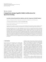
capacity. The algorithm is tested with spatial triplets, spatial
quads, cross-color triplets, and quads. The images used
are Lena, Baboon, and Fruits (512
× 512 RGB images). In
all experiments; T
1
= T
2
= T
3
. In the case of spatial
triplets, the payload size against PSNR of the watermarked
images is depicted in Figure 4(a). The performance of
the algorithm is lower with Baboon than with Len a or
Fruits.WithFruits, the algorithm is able to embed 858 kb
(3.27 bits/pixel) with an image quality (PSNR) of 28.52 dB
or only 288 kb (1.10 bits/pixel) with reasonably high image
quality of 37.94 dB. On the contrary, with Baboon, the
algorithm is able to embed 656 kb (2.5 bits/pixel) at 21.2 dB
and 115 kb (0.44 bits/pixel) at 30.14 dB. In the case of
spatial quads, the payload size against PSNR is plotted in
Figure 4(b). In this case, the algorithm performs slightly
better with Fruits.InthiscasewithFruits, the algorithm is
able to embed 508 kb (1.94 bits/pixel) with image quality of
33.59 dB or alternatively 193 kb (0.74 bits/pixel) with high
image quality of 43.58 dB. Again with Baboon, apayload
of 482 kb (1.84 bits/pixel) at 24.73 dB and of only 87 kb
(0.33 bits/pixel) at 36.6 dB are achieved. In general, the
quality of the watermarked images, using spatial quads,
is better than the quality obtained with spatial triplets
algorithm (the sharpening effects is less noticeable). The
payload size versus PSNR for cross-color triplets and cross-
color quads are shown in Figures 4(c) and 4(d),respectively.
For a given PSNR, the spatial vector technique is better than
the cross-color vector method. The comparison between
these results demonstrates that the cross-color algorithms
(triplets and quads) have almost the same performance with
all images (except Le na at PSNR greater than 30 dB). From
the results above and from the comparison with Celik and
Tian, the spatial quad-based technique, that provides high
capacity and low distortion, would be the best solution for
most applications.
Wen g et al. [ 9] proposed high-capacity reversible data
hiding scheme, to solve the problem of consuming almost
all the available capacity in the embedding process noticed in
various watermarking techniques. Each pixel S
i
is predicted
by its right neighboring pixel (
S
i
) and its prediction-error
P
e,i
= S
i
−
S
i
is determined (see Figure 5).
P
e,i
is then companded to P
Q,i
by applying the quantized
compression function C
Q
according to the following.
P
Q
=C
Q
(
P
e
)
=
⎧
⎪
⎪
⎨
⎪
⎪
⎩
P
e
|P
e
|<T
h
sign
(
P
e
)
×
|
P
e
|−T
h
2
+T
h
|
P
e
|≥T
h
,
(17)
where T
h
is a predefined threshold; the inverse expanding
function is described in the following .
E
Q
P
Q
=
⎧
⎨
⎩
P
Q
P
Q
<T
h
sign
P
Q
×
2
P
Q
−
T
h
P
Q
≥
T
h
.
(18)
The so-called companding error is r
=|P
e
|−|E
Q
(P
Q
)|
which is 0 if |P
e
| <T
h
.
Embedding is performed according to (19)(S
w
i
is the
watermarked pixel and w is the watermark), on the basis of a
classification into two categories: C
1
if S
w
i
does not cause any
over/underflow, C
2
otherwise.
S
w
i
=
S
i
+2P
Q
+ w.
(19)
Pixel belonging to C
1
which will be considered for
watermarking, are further divided into two subsets C
<T
h
and C
≥T
h
in dependence if P
e,i
<T
h
or not respectively.
The information to be embedded are: a lossless compressed
location map, containing 1 for all pixels in C
1
and 0
for all pixels in C
2
, whose length is L
s
, the bitstream R
containing the companding error r for each pixel in C
≥T
h
and the watermark w. The maximum payload is given by
the cardinality of C
1
reduce d by numb er of C
≥T
h
and by
the length of L
s
. The extraction process follows reversely the
same steps applied in embedding. All LSBs are collected and
then the string of the location map which was identified
by an EOS is recovered and decompressed, after that the
classification is obtained again. Restoring is firstly performed
through prediction by using the following.
P
Q,i
=
S
w
i
−
S
i
2
,
w
= Mod
S
w
i
−
S
i
,2
,
(20)
where
S
i
, the predicted value, is equal to S
i+1
in this case. On
the basis of the presented experimental results, the algorithm
globally outperforms the Tian’s method [4] and the Thodi’s
one [3] from the capacity-vs-distortion p oint of view: for
instance it achieves 0.4bpp and grants 41dB of PSNR. In
particular, performances seem to be better when textured
images, such as Baboon, are taken into account.
EURASIP Journal on Information Security 7
1E +05
2E +05
3E +05
4E +05
5E +05
6E +05
7E +05
8E +05
9E +05
1E +06
20 25 30 35 40 45 50
PSNR
Payload (bits)
(a)
20 25 30 35 40 45 50
PSNR
Payload (bits)
6E +05
5E +05
4E +05
3E +05
2E +05
1E +05
0E +00
(b)
20 25 30 35 40 45 50
PSNR
Payload (bits)
Lena
Fruits
Baboon
3E +05
2.5E +05
2E +05
1.5E +05
1E +05
5E +04
0E +00
(c)
20 25 30 35 40 45 50
PSNR
Payload (bits)
Lena
Fruits
Baboon
3E +05
2.5E +05
2E +05
1.5E +05
1E +05
5E +04
0E +00
(d)
Figure 4: (a) Spatial Triplets, (b) Spatial Quads, (c) Cross-col Triplets and (d) Cross-col Quads.
Prediction
Pixel S
i
Classification
x2
S
i
P
e,i
P
Q,i
C
0
(·)
−
w
S
w
i
C
1
C
2
P
Q
S
i
Data
embedding
Figure 5: Embedding process.
In Coltuc [10], a high-capacity low-cost reversible water-
marking scheme is presented. The increment in capacity is
due to the fact that it is not used any particular location
map to identify the transformed pairs of pixels (as usually
happens). The proposed scheme, adopts a generalized integer
transform for pairs of pixels. The watermark and the
correction data, needed to recover the original image, are
embedded into the transformed pixel by simple additions.
This algorithm can provide for a single pass of watermarking,
bitrates greater than 1 bpp.
Let us see how the integer transform is structured. Given
a gray-level (L
= 255) image and let x = (x
1
, x
2
) be a pair
of pixels and n
≥ 1 be a fixed integer, the forward transform
y
= T(x), where y = (y
1
, y
2
) is given in the following.
y
1
=
(
n +1
)
x
1
− nx
2
,
y
2
=−nx
1
+
(
n +1
)
x
2
,
(21)
where x
1
and x
2
belong to a subdomain contained within
[0, L]
× [0, L] to avoid under/overflow for y
1
and y
2
.The
inverse transform x
= T
−1
(y) is instead given in the
following.
x
1
=
(
n +1
)
y
1
+ ny
2
2n +1
,
x
2
=
(
n
)
y
1
+
(
n +1
)
y
2
2n +1
,
(22)
8 EURASIP Journal on Information Security
which is basically based on the fact that the relations in (23)
(called congruence)hold
(
n +1
)
y
1
+ ny
2
≡ 0mod
(
2n +1
)
,
ny
1
+
(
n +1
)
y
2
≡ 0mod
(
2n +1
)
.
(23)
If a further modification is applied (i.e., w atermarking)
through an additive insertion of a value a
∈ [0, 2n], like in
(24), (23) are not anymore satisfied by the new couple of
pixels.
y
1
, y
2
−→
y
1
+ a, y
2
.
(24)
In addition, it is important to point out that a nontrans-
formed pair does not necessarily fulfill (23), but it can be
demonstrated that it always exists an a
∈ [0, 2n]toadjust
the pair in order to fulfill ( 23). On this basis, before the
watermarking phase, all the couples are modified to satisfy
(23) and then the watermark codewords (let us suppose that
they are integers in the range [1, 2n]) are embedded into
the transformed pixel couples by means of (24). For the
watermarked pairs, (23) no longer holds so they are easily
detectable. Another constraint must be imposed to prevent
pixel overflow
x
1
+2n ≤ L,
x
2
+2n ≤ L.
(25)
During watermarking , all pairs which do not cause
under/overflow are transform ed, on the contrary not trans-
formed ones are modified according to (24)tosatisfy(23),
and the corresponding correction data are collected and
appended to watermark payload.
During detection, the same pairs of pixels are identified
and then, by checking (23) if the result is 0 or 1 not-
transformed and transformed (bringing the watermark)
couples are respectively individuated. The watermark is
recovered and split in correction data and payload; if the
embedded information is valid, both kinds of pairs are
inverted to recover the original image. Given p the number of
pixel pairs, where t is the transformed ones and being [1, 2n]
the range for the inserted codeword, the hiding capacity is
basically equal to
b
(
n
)
=
t
2p
log
2
(
2n
)
−
p − t
2p
log
2
(
2n +1
)
bpp.
(26)
In the proposed scheme, the bitrate depends on the
number of transformed pixel pairs and on the parameter n.
The experimental results for Lena show that, a single pass
of the proposed algorithm for n
= 1 gives a bit-rate of
0.5 bpp at a PSNR of 29.96 dB. In the case of n
= 2 the bit-
rate is almost 1 bpp with a PSNR of 25.24 dB. By increasing
n, the bit-rate becomes greater than 1 bpp obtaining a
maximum bit-rate for n
= 6, namely 1.42 bpp at a PSNR of
19.95 dB. As n increases, the number of transformed pairs
decreases. However, for highlytextured images like Baboon
performances are sensibly lower.
In [11], Coltuc improves the algorithm previously pre-
sented [10]. A different transform is presented: instead of
embedding a single watermark codeword into a pair of
transformed pixels, now the algorithm embeds a codeword
into a single transformed pixel. Equation (27) defines the
direct transform.
y
i
=
(
n +1
)
x
i
− nx
x+1
,
(27)
while the inverse transform is given by the following.
x
i
=
y
i
+ nx
x+1
n +1
.
(28)
This time the congruence relation is given by by the
following.
y
i
+ nx
i+1
≡ 0mod
(
n +1
)
.
(29)
Then the technique proceeds similarly to the previ-
ous method by distinguishing in transformed and not-
transformed pixels. The hiding capacity is now
b
(
n
)
=
t
N
log
2
(
n
)
−
N − t
N
log
2
(
n +1
)
bpp,
(30)
where t is the number of transformed pixels and N is the
number of image pixels.
The proposed algor ithm is compared with the previous
work [10]. This new technique provides a significant gain
in data hiding capacity while, on the contrary, achieves low
values of perceptual quality in terms of PSNR. Considering
the test image Lena, a single pass of the proposed algorithm
for n
= 2 gives a bit-rate of 0.96 bpp. The bit-rate is almost
the same of [10], but at a lower PSNR (22.85 dB compared
with 25.24 dB). For n
= 3 one gets 1.46 bpp at 20.15 dB
which already equals the maximum bit-rate obtained with
the scheme of previous work; namely, 1.42 bpp at 19.95 dB
(obtained for n
= 6). By increasing n, the bit-rate increases:
for n
= 4 one gets 1.77 bpp, for n = 5 the bit-rate is
1.97 bpp, for n
= 6 the bit-rate is 2,08 bpp and so on, up
to the maximum value of 2.19 bpp obtained for n
= 9. The
same problems when dealing with highly textured images are
presented.
In Chang et al. [12], two spatial quad-based schemes
starting from the difference expansion of Tian [4] algorithm
are presented. In particular, the proposed methods exploit
the property that the differences between the neighboring
pixels in local regions of an image are small. The difference
expansion technique is applied to the image in row-wise and
column-wise simultaneously.
Let (x
1
, x
2
) be a pixel pair, the Integer Haar wavelet
transform is applied as follows
a
=
x
1
+ x
2
2
, d = x
1
− x
2
, (31)
and a message bit m is hidden by changing d to d
= 2×d+m.
The inverse transform is
x
1
= a +
d +1
2
, x
2
= a −
d
2
,
(32)
and then d and m are restorable by using the following.
d
=
d
2
, m = d
− 2 ×
d
2
.
(33)
EURASIP Journal on Information Security 9
a
11
a
12
a
21
a
22
b
Figure 6: The partitioned image I
n×n
and a 2 × 2blockb.
In the proposed scheme, the host image I
n×n
is firstly
partitioned into n
2
/42 × 2 blocks (spatial quad-based
expansions, see Figure 6).
To establish if a block b is watermarkable, the measure
function, presented in (34) which assumes boolean values, is
considered.
ρ
(
b, T
)
=
(
|a
11
− a
12
|≤T
)
∧
(
|a
21
− a
22
|≤T
)
∧
(
|a
11
− a
21
|≤T
)
∧
(
|a
12
− a
22
|≤T
)
,
(34)
where b is a 2
× 2 block, T is a predefined threshold, a
11
,
a
12
, a
21
,anda
22
are pixel values in b, ∧ is the “AND”
operator. If ρ(b, T)istrue, b is chosen for watermarking,
otherwise b is discarded. Two watermarking approaches
are proposed. In the first one, row-wise watermarking is
applied to those blocks satisfying the relation (a
11
− a
12
) ×
(a
21
− a
22
) ≥ 0 which determines that (34) still holds
for watermarked values and consequently to apply column-
wise watermarking. Bindings to avoid over/underflow are
imposed to watermarked pixels both for row-wise embed-
ding and for column-wise one. In the second approach
initial relation is not required anymore, only over/underflow
is checked, and a 4-bit m essage is hidden in each block.
In both cases, a location map to record the watermarked
block is adopted; such location map is compressed and
then concealed. The algorithm is tested on four 512
× 512
8 bit grayscale images, F16, Baboon, Lena, and Barbara.The
results, in terms of capacity versus PSNR, are compared
with other three algorithms, proposed by Thodi, Alattar
and Tian. All methods are applied to images only once.
From the comparison, the proposed algorithm can conceal
more information than Tian’s and Thodi’s methods, while
the performances of Alattar scheme are similar. In general,
the proposed scheme is better than Alattar at low and
high PSNRs. For middle PSNR Alattar’s algorithm perfor ms
better.
Weng et al. presented in [13] a reversible data hiding
scheme based on integer transform and on the correlation
among four pixels in a quad. Data embedding is per formed
by expanding the differences between one pix el and each
of its three neighboring pixels. Companding technique is
adopted too. Given a grayscale image I,each2
× 2adjacent
pixels are grouped into nonoverlapping quads q
q
=
u
0
u
1
u
2
u
3
, u
0
, u
1
, u
2
, u
3
∈ N. (35)
The forward integer transform T(
·)isdefinedas
v
0
=
u
0
+ u
1
+ u
2
+ u
3
4
,
v
1
= u
0
− u
1
,
v
2
= u
0
− u
2
,
v
3
= u
0
− u
3
(36)
while the inverse integer transform T(
·)
−1
is given by
u
0
= v
0
+
v
1
+ v
2
+ v
3
4
,
u
1
= u
0
− u
1
,
u
2
= u
0
− u
2
,
u
3
= u
0
− u
3
.
(37)
The watermarking process starts with the transformation
T(
·) of each quad and then proceeds with the application
of a companding function (see [9] for detail) whose output
values are classified into three categories C
1
, C
2
,andC
3
,
according to specified characteristics. Quads belong ing to
the first two categories are watermarked, the others are
left unmodified; finally T(
·)
−1
is applied to obtain the
watermarked image. The to-be-inserted watermark is the
composition of payload, location map and original LSBs.
During extraction, quads are recognized again and then
the transformation T(
·) is applied; a fter that the quad
classification is performed by resorting to the location map
recovery. Finally, the watermark is extracted and image
restoration is achieved by computing T
−1
.
The algorithm is tested and compared with Tian’s and
Alattar’s method on several images including 512
× 512 Le na
and Barbara. Embedding rates close to 0.75 bpp are obtained
with the proposed and the Alattar’s algorithm without
multiple embedding, while multiple embedding is applied to
Tian’s algorithm to achieve rates above 0.5 bpp. From results
the proposed method presents a PSNR of 1–3 dB more than
the others with a payload of the same size. For example,
considering Lena, in the proposed method the embedding
capacity of 0.3 bpp is achieved with a PSNR of 44 dB, while
in Tian, the PSNR is 41 db and in Alattar is 40 db. The
embedding capacity of 1 bpp is achieved with a PSNR of
32 db for the proposed method, while in this case in Tian
10 EURASIP Journal on Information Security
0
50
100
150
200
250
0 50 100 150 200 250
Peak point
Zero
point
(a)
0
50
100
150
200
250
0 50 100 150 200 250
The original peak
point disappears
(b)
Figure 7: (a) Histogram of Lena image, (b) Histogram of water-
marked Lena image.
and Alattar the PSNR is 30 db. For Baboon, the results show
that for a payload of 0.1 bpp a PSNR of 44 db, 35 db, and
32 db for the proposed method, Tian and Alattar is achieved,
respectively. In general, the proposed technique outperforms
Alattar and Tian at almost all PSNR values.
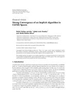
In [14], Ni et al. proposed a reversible data hiding
algorithm which can embed about 5–80 kb of data for a
512
× 512 × 8 grayscale image with PSNR higher than 48 dB.
The algorithm is based on the histogram modification, in
the spatial domain, of the original image. In Figure 7(a), the
histogram of Lena is represented.
Given the histogram of the original image the algorithm
first finds a zero point (no value of that gray level in the
original image) or minimum point in case that zero point
does not exist, and then the peak point (maximum frequency
of that gray level in the original image). In Figure 7(a) h(255)
represents the zero point and h(154) represents the peak
point. The number of bits that can be embedded into an
image, equals to the frequency value of the peak point.
Let us take this histogram as an example. The first step in
the embedding process (after scanning in sequential order)
is to increase by 1, the value of pixels between 155 and
254 (including 155 and 254). The range of the histogram
is shifted to the right-hand side by 1, leaving the value
155 empty. The image is scanned once again in the same
sequential order, when a value of 154 is encountered, such
value is incremented by 1, if the bit value of the data to embed
Table 4: Experimental results for some different images.
Images
(512
×512)
PSNR of marked
image (dB)
Pure
payload (bits)
Lena 48.2 5,460
Airplane 48.3 16,171
Tiffany 48.2 8,782
Jet 48.7 59,979
Baboon 48.2 5,421
Boat 48.2 7,301
House 48.3 14,310
Bacteria 48.2 13,579
Blood 48.2 79,460
is 1; otherwise, the pixel value remains intact. In this case,
the data embedding capacity corresponds to the frequency of
peak point. In Figure 7(b) the histogram of the marked Lena
is displayed.
Let be a and b,witha<b, the peak point and the
zero point (or minimum point), respectively, of the marked
image. the algorithm scan in sequential order (the order used
in embedding phase) the marked image. When a pixel with
its grayscale value a+1, is encountered, a bit “1” is extracted.
If a pixel with its value a is encountered, a bit “0” is extracted.
The algorithm described above is applied in the simple
case of one pair of minimum point and maximum point.
An extension of the proposed method considers the case
of multiple pairs of maximum and minimum points. The
multiple pair case can be treated as the multiple repetition
of the technique for one pair case. The lower bound of
the PSNR of the marked image generated by the proposed
algorithm can be larger than 48 dB. This value derives from
the following equation.
PSNR
= 10 log
10
255
2
MSE
=
48.13 dB. (38)
In embedding process the value of pixel (between the
minimum and maximum point) is added or subtracted
by 1. In the worst case, MSE
= 1. Another advantage
of the algorithm is the low computational complexity.
Also the experimental results demonstrate that the overall
performance of the proposed technique is good and better
than many other reversible data hiding algorithm. In Table 4,
results, in terms of PSNR and payload, of an experiment with
some different images are shown.
2.2. Transformed Domain. In this subsection, works dealing
with fragile reversible watermarking operating on trans-
formed domain are presented.
An interesting and simple technique which uses quan-
tized DCT coefficients of the the to-be-marked image has
been proposed by Chen and Kao [15]. Such an approach
resorts to three parameters adjustment rules: ZRE (Zero-
Replacement Embedding), ZRX (Zero-Replacement Extrac-
tion), and CA ( Confusion Avoidance); the first two are
EURASIP Journal on Information Security 11
adopted to embed and extract one bit, respectively, the
third one is to prevent confusion during embedding and
extraction. Hereafter, these three rules are listed.
ZRE: embeds one bit into (a, 0, 0) satisfying a
/
= 0as
follows.
(1) Change (a,0,0)to(a, 1, 0) as embedding bit 1.
(2) Change (a,0,0)to(a,
−1, 0) as embedding bit 0.
ZRX: extract one bit from (a, b,0) when b
= 1or−1as
follows.
(1) Extract bit 1 from (a, 1, 0) and modify them to
(a,0,0).
(2) Extract bit 0 from (a,
−1, 0) and modify them
to (a,0,0).
CA: proposed to avoid embedding or extracting error.
(1) In embedding, each (a, k,0) are changed to
(a, k + 1, 0) when a
/
= 0, k>0orchangedto
(a, k
− 1, 0) when a
/
= 0, k<0.
(2) In extracting, each (a, k,0) are changed to
(a, k
− 1, 0) when a
/
= 0, k>0orchangedto
(a, k + 1, 0) when a
/
= 0, k<0.
To perform embedding, the image is partitioned in 8
× 8
blocks and each of them is DCT transformed and quantized.
Then, on the basis of a predetermined selection sequence,
triplets of coefficients are selected and preprocessed by
applying CA r u le. Finally, the watermark bits are embedded
through ZRE rule into valid triplets (i.e., with the format
(a,0,0) where a
/
= 0) and IDCT is computed to obtain the
watermarked image. During extraction, all the initial steps
are repeated as well until when triplets are constructed
again; ZRX rule is applied to all the valid triplets, thus the
watermark is read and the original coefficients are recovered.
By using CA rule, all the other triplets are converted back
to their original values too. Finally IDCT is obviously
computed. Experimental results show that with Lena 512
×
512 a payload of 7459 bits can be embedded and at the same
time a PSNR of 36.16 dB can be granted; similar values are
provided for Cameraman (payload of 6794 bits and PSNR of
37.34 dB).
Another work based on integer DCT coefficients modifi-
cation has been proposed by Yang et al. [16]. The reversibility
is guaranteed by integer DCT, a lossless 8
× 8block
transform, is applied to the whole image; the algorithm
exploits the principle of histogram modification proposed
by Ni et al. [14]. The integer DCT tra nsform has the
property of energy concentration which can be used to
improve the capacity of histogram modification scheme.
The watermarking process starts with dividing the image
into M blocks with size 8
× 8 and computing the integer
DCT. Within each transformed block, the M co efficients in
position (p, q)(1
≤ p, q ≤ 8) are selected to form 64
coefficient groups G(p, q) and for every group an histogram
is created. Histogram modification is then applied to insert
the watermark only to AC groups. In some applications,
it can be used a secret key K
c
to select N (N<63)
coefficient groups for watermarking. For each histogram of
the total N coefficient groups, the positions of the original
peak point P and zero point Z which are involved in
modification, must be recorded as overhead information
needed during the extraction process. The extraction process
is simply the reversed of the embedding process. The
presented experimental results say that with Lena 256
× 256,
10541 bits of payload are achievable with a PSNR of almost
45 dB.
In Weng et al. [17], a data hiding scheme, based on
companding technique and an improved difference expan-
sion (DE) method is presented. The payload is embedded
into high frequency bands (LH, HL, and HH) in the integer
wavelet transform domain (IWT), using the compand-
ing technique. To solve the overflow/underflow problem,
after IWT, a method based on histogram modification is
proposed. Such algorithm is based on Xuan’s technique
[18], which suffered the problem of overflow/underflow.
Weng avoids that problem by interchanging the order
of histogram modification and IWT. The advantages are
basically an increment in hiding capacity w ith the PSNR
value slightly increased and an overall PSNR improvement.
Watermark embedding is divided into two steps: firstly,
the image I is IWT-transformed and the watermark w
is embedded into the LSB of one bit left shifted version
of an IWT selected coefficient; after that inverse, IWT is
applied and the image I
is obtained. I
could be ou t of
range [0, 255] and to guarantee that such value are into
such a range, an histogram modification technique is used
andanimprovedDEmethodisadoptedtoembedinfor-
mation regarding this modification into I
H
(the modified
I
) to achieve, finally, I
w
.SuchimprovedDEmethodis
based on a classification which divides each difference into
three categories: expandable, changeable and nonchange-
able.
The extraction process is composed by two stages: in the
first one, classification is performed again and DE embed-
ding is inverted till retrieving I
H
and information about
histogram modification. After that, histogram modification
is inversely applied and then the obtained image is IWT-
transformed. High frequencies subbands are selected and
the watermark is extracted. Finally inverse IWT is computed
to retrieve the original image. Experimental results witness
that a payload of 0.6 bpp with a correspondent PSNR of
40 dB is achieved for Len a 256
× 256. The same capacity
is obtained for Baboon 512
× 512 but with a PSNR of
30 dB.
Lee et al. [19] proposed a reversible watermarking
scheme with high embedding capacity. The input image is
divided into non-overlapping blocks, and the watermark is
embedded into the high-frequency wavelet coefficients of
each block. To guarantee the reversibility, invertible integer
to integer wavelet transforms are used, by applying the Lazy
wavelet and the lifting construction (finite length filter),
to avoid loss of information through forward and inverse
transform. The watermark is embedded into the wavelet
coefficients using two techniques, the LSB-substitution or the
bit-shifting (specifically p-bit-shifting). In the first case, the
12 EURASIP Journal on Information Security
watermark is embedded by replacing the LSB of the selected
wavelet coefficient with the watermark bit.
c
w
= 2 ·
c
2
+ w, (39)
where c is the original coefficient, c
w
is the watermarked
coefficient and w is the watermark bit. In the second case, the
original coefficient c is multiplied by 2
p
,wherep is a positive
integer, and the watermark bit w is embedded into its p LSBs
c
w
= 2
p
· c + w
, (40)
where w
= 2
0
· w
0
+2
1
· w
1
+ ··· +2
p−1
· w
p−1
and
{w
0
, w
1
, , w
p−1
} is a set of p watermark bits. During this
phase, an overflow or underflow problem, in the correspond-
ing spatial domain, can occur. To achieve the reversibility,
underflow and overflow must be predicted before watermark
embedding identifying the LSB-changeable and bit-shiftable
imageblocks.Asdefined,animageblockissaidtobeLSB-
changeable when a watermark bitstream can be embedded
into the LSBs of its high-frequency wavelet coefficients using
the LSB-substitution without any underflow or overflow
in the spatial domain, bit-shiftable or, specifically, p-bit-
shiftable, when a watermark bitst ream can be embedded into
its high-frequency wavelet coefficients using the bit-shifting
without any u nderflow or overflow in the spatial domain. To
understand how to avoid overflow and underflow Figure 8
is to be considered. It displays the scheme of forward and
inverse wavelet transform and watermark embedding.
First, an M
× N pixel block S is transformed into a
block of M
× N wavelet coefficients C using the integer-to-
integer transform IntDWT2(
·). Next, a block C
M
is obtained
by setting the LSBs of the chosen coefficients to zero or by
applying bit-shifting to the chosen coefficients in C.The
modified pixel block S
M
is obtained by applying the 2-D
inverse flo ating-point (fDWT2
−1
(·)) wavelet transform to
C
M
. By adding a watermark bit block W to C
M
,ablock
of watermarked wavelet coefficients C
W
is obtained. Then,
S
WF
and S
WI
are obtained by applying fDWT2
−1
(·)and
IntDWT2
−1
(·)toC
W
, respectively. The embedding error E
W
is obtained by applying fDWT2
−1
(·)toW. Using a floating-
point wavelet transform, overflow and underflow, caused
by watermarking in the wavelet domain, can be predicted
exploiting the linearity of the transform. From Figure 8,it
derives that,
S
WF
= fDWT2
−1
(
C
W
)
= fDWT2
−1
(
C
M
+ W
)
= fDWT2
−1
(
C
M
)
+fDWT2
−1
(
W
)
= S
M
+ E
W
.
(41)
The underflow or overflow depend on the error Ew
introduced by the embedded watermark W. In this case, two
matrices E
WP
and E
WN
, whose elements represent limits of
max positive and negative errors caused by the embedding
process are shown in the following.
E
WP
=
i, j∈(HL
1
∪LH
1
∪HH
1
)
1
2
Q
ij
+ABS
Q
ij
,
E
WN
=
i, j∈(HL
1
∪LH
1
∪HH
1
)
1
2
Q
ij
− ABS
Q
ij
,
(42)
where Q
ij
= fDWT2
−1
(O
ij
), O
ij
is the matrix with only one
nonzero element of value 1 in the ith row and jth column.
Since E
W
satisfy the inequalit y E
WN
(m, n) ≤ E
W
(m, n) ≤
E
WP
(m, n), the overflow and underflow will not occur in S
for any watermark block W if
s
min
− E
WN
(
m, n
)
≤ S
M
(
m, n
)
≤ s
max
− E
WP
(
m, n
)
,
(43)
for 0
≤ m<M,0≤ n<N.
During embedding process, the watermarked image
block obtained is S
WI
= IntDWT2
−1
(C
W
). The integer
to integer wavelet transforms introduce a roundoff error
(caused by truncation). The roundoff error matrix E
R
can
be defined, as represented by E
WP
E
WN
,bytwomatrixE
RP
and E
RN
. In case of integer to integer wavelet transform that
approximates LeGalle 5/3 filter, E
RP
and E
RN
are shown in the
following.
E
RP
=−E
RN
=
⎡
⎢
⎢
⎢
⎢
⎢
⎢
⎢
⎢
⎢
⎢
⎢
⎢
⎣
1.2521.2521.2521.25 2
23232323
1.2521.2521.2521.25 2
23232323
1.2521.2521.2521.25 2
23232323
1.2521.2521.2521.25 2
23232323
⎤
⎥
⎥
⎥
⎥
⎥
⎥
⎥
⎥
⎥
⎥
⎥
⎥
⎦
.
(44)
Introducing such error, the watermarked image block S
WI
is given now by
S
WI
= IntDWT2
−1
(
C
W
)
= IntDWT2
−1
(
C
M
+ W
)
= fDWT2
−1
(
C
M
+ W
)
+ E
R
= S
M
+ E
W
+ E
R
.
(45)
An image block S can be said LSB-changeable or bit-
shiftable for any watermark block W if (46) is satisfied.
s
min
− E
WN
(
m, n
)
− E
RN
(
m, n
)
≤ S
M
(
m, n
)
≤ s
max
− E
WP
(
m, n
)
− E
RP
(
m, n
)
,
(46)
for 0
≤ m<M,0≤ n<N.
The proposed algorithm uses also a location map L
(binary matrix) that indicates which blocks are watermarked.
EURASIP Journal on Information Security 13
C
+
S
M
S
WI
S
W
C
M
S
E
W
F
C
W
LSB-clear
or
bit-shifting
Watermarking
embedding
W
IntDWT2
fDWT2
−1
fDWT2
−1
IntDWT2
−1
fDWT2
−1
Figure 8: Forward and inverse wavelet transform and watermark embedding.
30
35
40
45
50
55
60
65
00.10.20.30.40.5
Embedding capacity (bit/pixel, bpp)
Image quality (PSNR, dB)
F-16
Lena
Barbara
Peppers
Fishing boat
Baboon
Figure 9: Comparison of embedding capacity versus PSNR for
some grayscale images.
This matrix is a part of the side information used in
decoding phase, and is embedded during the watermarking
process. The decoding algorithm starts dividing the water-
marked image into non-overlapping M
× N blocks. The
transformation applied to each block uses the same wavelet
utilized in the embedding scheme. Next L SB-changeable
blocks are searched. When the process identifies the LSB-
changeable blocks, the location map is recovered (through
the LSBs of the high frequency wavelet coefficients), the
watermarked blocks are searched and the payload (original
LSBs and message bits) extracted. From the original LSBs
and the location map, the original image block can be recon-
structed. The experimental results show that the proposed
scheme has higher embedding capacity, compared with other
existing reversible algorithm. Figure 9 shows the quality of
watermarked images at various embedding capacities with
block size of 16
× 16. The size of the block determines the
performance of the proposed algorithm. If the block size is
too smal l (4
× 4) or too large (32 × 32), the performance of
the algorithm is degraded.
3. Semi-Fragile and Robust Algorithms
In this section the second category of algorithms belonging
to the class of semi-fragile and robust is introduced. Such
techniques present the characteristic to grant a certain degree
of robustness when a specific process is applied to the
watermarked image: this means that the image is still asserted
as authentic.
3.1. Semifragile Algorithms
3.1.1. Spatial Domain. De Vleeschouwer et al. proposed in
[20], a semi-fragile algorithm based on the identification of a
robust feature of the luminance histogram for an image tile.
As for the patchwork approach, the cover media is tiled in
non-overlapping blocks of pixels that are associated to a bit
of the embedded message.
For a single block, the pixels are equally divided into two
pseudorandom sets (i.e., zones A and B)andforeachzone
the luminance histogram is computed and mapped around a
circular support. A weight, proportional to the occurrence
of each luminance value, is placed on the corresponding
position of the circle and then a center of mass is calculated
and localized respect to the center of the circle.
Since zones A and B are pseudo-randomly determined, it
is highly probable that the localization of the corresponding
centers of mass are very close to each other. This peculiarity
can be exploited to embed a bit by simply rotating the center
of mass of the A and B zones in opposite ways. A clockwise
rotation of the A zone center of mass can be associated to the
embedding of a bit “1,” while an anticlockwise rotation can
be associated to a bit “0.” The B zone is rotated in the opposite
direction accordingly to the technique previously presented.
By using this approach, it is very easy to determine,
during the watermark detection, if a “1” or “0” bit is
embedded in a certain block and, eventually, remove the
mark by counter rotating the histogram along the circular
support.
In a real image, some pathological cases can arise when
the two centers of mass are not properly positioned and
in general do not respect the mutual nearness. These cases
are statistically negligible and do not affect sig nificantly the
available watermark payload.
14 EURASIP Journal on Information Security
If the histogram is mapped linearly into the circular
support, salt and pepper noise can appear because of the
abrupt transition on the occurrences of the 255-level to the
0-level and vic eversa even for a small support rotat ion. To
cope with this problem, the histogram can be mapped to the
support in an alternative fashion by mapping clockwise the
1st, the 5th histogram value, and so forth.
Because of the rearrangement of the histogram on
the support, the center of mass for the A and B zones
appear very close to the center of the circle making the
watermark detection less reliable. In this case, the center
of mass computation is substituted by the computation of
the minimal inert ia axis that can be detected more easily.
This alternative technique make the salt and pepper noise
disappear. Both these approaches can cope with acceptable
lossy attacks such cropping (by embedding a synchronization
grid) and JPEG compression. The proposed methods show
a good robustness, even if the second one, while more
appealing from a perceptual point of view, is more fragile to
JPEG compression.
In Ni et al. [21], an algorithm based on the De
Vleeschouwer idea is proposed in order not to be fragile to
JPEG compression. This method is based upon an analysis
of the differences between couples of pixels belonging to an
image tile.
An image tile is divided into pixel couples and a sum
of differences of their luminance values (taken in an ad
hoc manner) is computed. A statistical analysis shows that
this computed value (named α) is very close to zero for
most of the tiles. The main idea for bit embedding is that
the difference value α is rela ted to a reference value K
(usually less than 5 according to numerous experiments) and
a categorization of the α value respect to the K value is carried
on. The categorization is defined even by means of the
parameter β that is usually β>2
· K. This approach is aimed
to avoid falling into underflow/overflow errors that would
significantly lower the stego image quality. In particular, four
categories are identified.
Category 1. The pixel grayscale values of a block under
consideration are far enough away from the two bounds of
the histogram (0 and 255 for an 8-bit grayscale image).
In this category, two other cases are further considered
according to the value of α.
(1) The value α is located between the range K and
−K.
(2) The absolute value of α exceeds the threshold K.
Category 2. Some pixel grayscale values of the block under
consideration are very close to the lower bound of the
histogram (0 for an 8-bit grayscale image).
In this category, two other cases are further considered
according to the value of α.
(1) The value α is located between the range K and
−K.
(2) The value of α is located on the right hand side
beyond the threshold K.
Category 3. Some pixel grayscale values of the block under
consideration are very close to the upper bound of the
histogram (255 for an 8-bit grayscale image).
In this category, two other cases are further considered
according to the value of α.
(1) The value α is located between the range K and
−K.
(2) The value of α is located on the left hand side beyond
the threshold K.
Category 4. Some pixel grayscale values of the block under
consideration are close to the upper bounds, while some
pixel grayscale values are close to the lower bounds of the
histograms.
In this category, two other cases are further considered
according to the value of α.
(1) The value α is located between the range K and
−K.
(2) The absolute value of α is beyond the threshold K.
Depending on the categories and on the cases the couples
of pixels are referrable to, the difference α can be increased
or decreased by β. The increment/decrement is always
implemented as a modification of the value of the higher
valued pixel of the pair. In some cases, α cannot be modified
without generating salt and pepper noise; in these case, no
modification are applied and then an error is inserted.
To cope with these insertion errors, the payload is
embedded with an Error Correction Code providing a suf-
ficient data redundancy. Authors states that BCH(63,7,15)
can correct most of the random errors that can be gener-
ated during the embedding process. In some cases, errors
concentrate in particular regions of the image (bursts of
errors) giving no chance to the ECC to recover data. In order
to deal with these situations, the authors used a message
bits permutation scheme to redistribute errors along the
entire image. Experimental results confirm that a significant
enhancement of the data embedding capacity and of the
PSNR of the marked image can be achieved respect to
the method proposed in [20]. The images used in the
experiments are Lena, Baboon, and Boat (512
× 512 × 8).
For Lena with a PSNR of 40.2 db the capacity is 792 bits,
but for the other two images the capacity is lower, in
fact in Baboon with a PSNR of 38.7 db the capacity is
585 bits while for Boat with a PSNR of 40.5 db the payload
is 560 bits. In par ticular, robustness is slightly increased
in the case of a lossy modification like JPEG/JPEG2000
compression with higher compression rates with respect to
[20]. For severe compression rates, instead, the results of the
proposed algorithm are comparable to those presented by De
Vleeschouwer. A unified authentication framework based on
the proposed methods has been included in the Security part
of JPEG2000 (known as JPSEC) IS (International Standard),
JPSEC ISO/IEC 15444-8:2007, April 2007.
3.1.2. Transformed Domain. Zou et al. [22]proposeda
semi-fragile lossless watermarking scheme based on the
5/3 (LeGalle 5/3 filter) integer wavelet transform (IWT)
EURASIP Journal on Information Security 15
×10
4
0
1
2
3
4
5
6
7
8
9
10
−100 −50 500 100
Figure 10: Histogram of the IWT coefficients in the HL sub-band
of JPEG2000.
integrated into JPEG2000 standard compression. T he water-
marking scheme embeds data into the IWT coefficients
of a selected high-frequency sub-band (HL, LH, and HH).
The proposed algorithm exploits a feature of the image
wavelet transform: the coefficients of the high-frequency
sub-band follow a zero-mean Laplacian-like distribution (see
Figure 10).
From this feature it is possible to deduce that dividing
the considered sub-band into non-overlapping blocks of
size nxn and calculating the mean of the coefficients values
in each block, the resulting mean values also have zero-
mean Laplacian distribution. The scheme starts scanning all
the blocks to find out the maximum absolute mean value
of coefficients, m
max
. A threshold T is set to the smallest
integer number greater than m
max
. The embedding phase,
manipulates the mean value of the block. Considering a
block, to embed a bit 1, the mean value of the block is shifted
by S (p ositive or negative, resp.). S is equal or larger than T.
To embed a bit 0, the mean value of the IWT coefficients in
the considered block is unchanged. In the extraction process,
when a mean value of the block with absolute value larger
than T is found, a bit
= 1 is recovered. If such mean value is
smaller than T abit
= 0 is recovered.
Since S is fixed for all blocks, the original coefficients
can be recovered to reconstruct the original image. The
reconstructed value is obtained by subtracting S from IWT
coefficients in the block where bit
= 1 is embedded. In this
case, the reversibility of the embedding process is guaranteed.
To prevent overflow and underflow, caused for example by a
conversion of the watermarked image from JPEG2000 format
to other, the authors present a block classification method
to identify which blocks can be modified during embedding
process. This classification divides the blocks into four
categories (see Figure 11). Each category is represented by
an histogram of the corresponding pixel values of the blocks
in the spatial domain. Assuming that the maximum absolute
pixel grayscale value (0–255) change is S
max
, the underflow
condition occurs when there are pixels with grayscale values
less than S
max
and the values need to be decreased in the
embedding process. The overflow condition, instead, occurs
0255
(a)
0255
S
(b)
0255
S
(c)
0255
(d)
Figure 11: Blocks classification. (a) Type A. (b) Type B. (c) Ty pe C.
(d) Type D.
Table 5: Block size versus capacity (Lena 512
× 512 × 8).
Block size ECC scheme Capacity Min shift values PSNR (dB)
5 (15,11) 1907 8 40.09
6 (15,11) 1293 6 41.87
7 (15,11) 950 4 44.81
8 (15,11) 750 4 44.36
9 (15,11) 574 4 44.18
10 (15,11) 458 2 49.86
11 (15,11) 387 2 49.62
12 (15,11) 323 2 49.46
when there are pixels with grayscale values greater than (255-
S
max
) and the values need to be increased. The worst case is
described in Figure 11(d); in this kind of block is not possible
to embed data (not-embeddable block). If during embedding
phase a bit 1 is embedded, in detection process the system can
extract this value without problems. Problems occur when
during detection process a bit 0 is detected. In this case, the
decoder is not able to decide if a bit 0 has been embedded or
the considered block is not embeddable. To solve the problem
and correct the errors, an ECC (Error Correction Code)
technique is used. The experimental results show that the
proposed method works well. No salt-and-pepper noise exist
and the visual quality of the watermarked images is much
higher compared with the method of De Vleeschouwer [20].
The PSNR of the proposed method are all over 38 dB. Zou
applies the algorithm to Lena, a 512
× 512 8-bit gray-scale
image and the per formance results, are shown in Tab le 5.Zou
algorithm’s is also robust to JPEG2000 lossy compression.
Wu [23] proposed a reversible semi-fragile watermarking
scheme for image authentication. This algorithm embeds a
watermark into LL
4
sub-band of the integer wavelet domain,
can restore the original image and can also locate the tamper
region. To embed data, the proposed scheme uses histogram
shifting of integer wavelet coefficients which grants higher
16 EURASIP Journal on Information Security
Table 6: PSNR values for some test images.
Test image
PSNR of marked
image (dB)
Test image
PSNR of marked
image (dB)
Lena 43.42 Peppers 43.46
Baboon 44.48 Barbara 43.45
Boat 43.47 Pentagon 43.46
visual quality of the watermarked image compared with
other algorithms reported in the literature. The method can
also tolerate JPEG compression at low quality factor. To
reconstruct the original image, the algorithm implements
a four-level integer wavelet transfor m , CDF 9/7, a bi-
orthogonal wavelet based on lifting scheme. The original
image can be obtained if the marked image has not been
altered. As seen in Zou [22], for most of the images,
the integer wavelet coefficients histogram, of the high-
frequency sub-band, follow a near zero-mean Laplacian-like
distribution. IWT coefficients values in the high-frequency
sub-band are concentrated near zero in the histogram.
This property is used to implement reversible data hiding.
Before to start with embedding process, the image is pre-
processed by histogram modification, to prevent underflow
or overflow. Then four-level IWT is performed on the pre-
processed image. The watermark is embedded in LL
4
sub-
band by inserting a five-bit code (one identifying “0” and
one “1”) by substituting the 5 LSBs of selected wavelet
coefficients. Information needed to reconstruct the original
image, are instead embedded reversibly by histogram shifting
in high-frequency sub-bands of the IWT domain. Finally,
inverse IWT is applied to obtain the marked image. During
detection and recovery step, the four-level IWT on the image
is performed. From LL
4
sub-band the hidden watermark
is extracted and authenticity is verified by comparing the
extracted watermark with the original known one. Due to
the spatial correlation granted by wavelet transform, possible
alterations are individuated by means of this comparison. If
the image is authentic, the original image is then recovered
from the marked one. To evaluate the performance of the
proposed algorithm, some common images, Lena, Baboon,
Barbara, Peppers, and so forth, are used. All images have a
size of 512
× 512 × 8 bits. In Tabl e 6, PSNRs of six marked
images are shown. The experimental results show that the
embedding distortion is small and a good visual quality of the
watermarked image is guaranteed. The proposed technique
can also resist JPEG lossy compression at a low qualit y factor.
3.2. Robust Algorithms
3.2.1. Spatial Domain. The algorithm presented in [24]is
based on histogram modification. Embedding is performed
by selecting a couples of histogram bins, hist(a) and hist(b),
and in order to insert a message bit 0 or 1, the following
rela tions are requ ired.
(i) m
= 0 → hist(a) < hist(b).
(ii) m
= 1 → hist(a) > hist(b).
If the asked relation does not already exist, bins are swapped
(pixels belonging to the bins are changed accordingly); if an
equality happens between selected bins, they are skipped.
Bins couples are individuated according to a public key
which is composed by a real number whose integer and
decimal parts are used to determine the initial bin (start)
and the distance between the two bins within each couple
(step), respectively. Couples are selected sequentially over
the histogram, in order to al l ocate all the message bits.
Furthermore, reference side information which records if
bins are swapped or not is constructed and passed to the
extractor, together with the watermark length and the public
key, to allow reversibility.
The capacity of this method is quite low (at most 128 bits
for a 256-gray level image) but, on the contrary, perceptual
quality is preserved (PSNR
≥ 40 dB for usual test images).
The algorithm presents a high robustness to different kinds
of attacks such as flipping, rotation (90
◦
, 180
◦
, and 270
◦
), up-
sizing, increasing aspect ratio, cropping (80%), drawing and
so on; resistance is reduced if the parameter (step)isnotover
5. JPEG compression, low pass filtering and noise addition
are not tolerated by this technique.
In Coltuc and Chassery [25], a technique based on
Reversible Contrast Mapping (RCM) which is a simple
integer transform applied to couples of pixels is presented.
RCM is invertible even if the LSBs of the transformed pixels
are lost. Being the image gray-level [0, L
= 255], the forward
RCM transform for the pair (x, y)isgivenin
x
= 2x − y, y
= 2y − x,
(47)
where x
and y
are limited to [0, L = 255] to avoid overflow
and underflow and consequently (x, y)mustbelongtoD
⊂
[0, L]×[0, L]. The inverse RCM transform is defined as in(48)
x
=
2
3
x
+
1
3
y
, y =
1
3
x
+
2
3
y
. (48)
It can be proved that (48)exactlyinverts(47) also if the
LSBs of the transformed pixels are lost; furthermore, if
x
and y
are not changed that holds also without using
the ceil functions. Due to this property, LSBs are used for
carrying the watermark. For sake of correctness, it can be
said that ceiling operation is robust to the loss induced
by watermarking only if both x
and y
are not both odd
numbers and this happens only if x and y are odd numbers
too. So odd couples would not be allowed for marking. To
overtake that, only a selected set of odd couples (x, y)(such
that the respective transformed values are not equal to 1 or L)
is taken; so the domain D is restricted to D
C
. After the image
is partitioned into pairs, embedding proceeds as follows.
(1) If (x, y)
∈ D
C
and it is not composed by odd pixel
values, (47) is applied and the LSB of x
is set to 1
(to indicate a transformed pair) and the LSB of y
is
available for watermark bit insertion.
(2) If (x, y)
∈ D
C
and it is composed by odd pixel values,
(47) is not applied and the LSB of x is set to 0 (to
indicate an odd pair) and the LSB of y is available for
watermark bit insertion.
(3) If (x, y)
/
∈ D
C
,(47) is not applied and the LSB of x is
set to 0 and the true LSB of x is saved in the payload.
EURASIP Journal on Information Security 17
ROI
RONI
ROI
Image
ROI identification
Protection le vel 1
Protection le vel 2
Authenticity
code metadata
Digital signature
computation
Digital signature
computation
RONI robust
embedder
Authenticity code
S
1
S
2
C
1
C
2
Reversible watermarking +
RONI data hiding
Authenticity code, metadata
Protected image
Figure 12: Embedding phase.
The watermark is composed by the payload and the bits saved
in the step 3. During detection, the image is partitioned again
into pairs (x
, y
) and,
(1) if the LSB of x
is 1 then the LSB of y
is a watermark
bit; after setting the LSBs of x
and y
to 0 the original
pair (x, y) is recovered by inverse RCM transform,
(2) if the LSB of x
is 0 and the pair (x
, y
) with the LSBs
set to 1 (odd) belongs to D
C
, then the LSB of y
is a
watermark bit; after setting the LSBs of x
and y
to 1
the original pair (x, y) is simply recovered, and
(3) if the LSB of x
is 0 and the pair (x
, y
) with the
LSBssetto1doesnotbelongtoD
C
, there is not
a watermark bit; after replacing the LSB of x
with
the true LSB taken from the watermark sequence, the
original pair (x, y) is reconstructed.
It is important to highlight that the embedding of
the true LSB of a nontransformed pair will happen in a
spatially close couple thus granting a slight robustness in
case of cropping, though experimental results on that are
not reported within the paper. Being P the global number of
couples and T the number of pairs carrying information, P
−
T will be the additional payload to attach to the watermark,
so the bit-rate B provided by the algorithm will be
B
=
T −
(
P
− T
)
2P
=
2T − P
2P
bit/pixel.
(49)
Further iterations can be applied to augment capacity to
the extent of increasing perceptual distortion. The proposed
scheme was tested on several graylevel and color images,
Lena, Baboon, and Boat. Applying the proposed scheme on
Lena without control distortion, a bit-rate of 0.49 bpp is
obtained. The bit-rate is very close to the theoretical upper
bound of 0.5 bpp. Further iterations of the scheme increase
the hiding bit-rate till 0.98, 1.40, 1.73, and 1.86 bpp. For low
and medium bit-rates, a slight increase of contrast can be
seen. Increasing the hiding capacity, the noise increases as
well. Boat is slightly lower, the maximum hiding capacity is of
1.53 bpp. Baboon provides only 0.84 bpp of embedding rate.
With a bitrate of 0.2bpp, a PSNR of 45db is achieved for
Lena. PSNR of 40 db and 32 db are achieved with Boat and
Baboon respectively with a bitrate of 1 bpp. The technique
outperforms other compression-based methods but it is
slightly worst than Tian’s difference expansion appro ach
though it appears less complex.
In Coatrieux et al. [26], robustness is achieved by mixing
two different approaches: one based on a reversible technique
and one based on a robust watermarking method, such an
approach is summarized with regard to the embedding phase
in Figure 12. This technique is basically devoted to deal with
MR (Magnetic Resonance) images in which is quite simple
to separate ROI (Region Of Interest) like the head or any
anatomical object, by the RONI (Region Of Non Interest)
which is the black background area behind the object. The
capacity to make such a distinction is fundamental to allow
18 EURASIP Journal on Information Security
the system to work, and it is very important to grant that
the watermarking process does not affect this segmentation
in the detection phase. According to what is pictured in
Figure 12, there are two protection levels. The first one
provides robustness to the watermark extraction, for instance
against JPEG compression, by watermarking with a lossy
robust method the RONI; the inserted code is composed by
an authenticity code and a digital signature derived from the
ROI.
The second protection level adopts a reversible technique
to cast, this time in the ROI, another code depending
upon the whole image (marked RONI plus ROI). The
global robustness is limited by the fact that a possible
attack determines a wrong reconstruction of ROI which
consequently influences watermark extrac tion at the first
protection level; in the paper, it is asserted that a JPEG
compression not lower than a quality factor of 70 does not
generate any bit error.
3.2.2. Transformed Domain. In the work presented in
[27], a quantization-based approach, named Weighted
Quantization Method, (WQM) is introduced. Being S
=
(s
1
, s
2
, , s
n
), the input signal and Q = (q
1
, q
2
, , q
m
)its
quantization levels, message bit embedding is achieved by
resorting to a couple of functions ( f , L). The function L,
according to the message bits m
= 0, 1 performs as it follows.
(i) L
0
(s) = The biggest quantization level greater than s.
(ii) L
1
(s) = The least quantization level smaller than s,
while function f works as
f
m
(
s
i
, L
m
(
s
i
))
=
s
i
+ dL
m
(
s
i
)
d +1
. (50)
The parameter d hastobemajororequalto1togrant
that the values obtained when embedding a bit 1 fall in a
range disjoint with respect to that for embedding a bit 0.
In addition to that, the higher the value of d the stronger
the image distortion; usually d is set to 1. According to the
definition of functions f and L, it yields that L
m
(s
) = L
m
(s
i
)
where s
is the watermarked signal; so for extracting the
message bit the quantization level closer to s
is chosen.
By using L
m
(s
i
) the watermarking process can be inverted
and the original value s
i
can be recovered. The approach
can be adopted both in spatial and transformed domain,
though the authors applied it after a Point to Point Graph
(PGP) transformation and experimental results are achieved
on such a basis. Robustness of such a method is very limited;
only BER against AWGN addition is presented within the
paper. High perceptual quality (PSNR around 42 dB) is
achievable with test images such as Lena and Baboon.
In Gao an d Gu [28], a procedure based on Alattar’s
difference expansion computed in the wavelet domain
is presented. 1-level IWT (Integer Wavelet Transform) is
applied to 8
× 8 blocks of the image and LL
1
sub-band
is considered; in particular, the four coefficients belonging
to the diagonal are grouped into two couples and used for
watermarking according to their expansibility. Expansibility
is checked to avoid overflow and underflow, and it is
recorded and passed as side infor mation to the detector side.
Image blocks are shuffled according to a secret key before
being wavelet transform, in order to achieve security and
robustness against some malicious attacks. The proposed
scheme is tested on Lena, Boat, and Baboon (512
× 512 × 8).
The achieved PSNRs are 35.8 db for Lena, 40.2 db for Boat
and 42 db for Baboon. Image reversibility is granted when no
attacks have happened and watermark robustness is partially
provided against cropping, salt and pepper noise, and other
image damaging localized in restricted zones.
4. Conclusions
Reversible digital watermarking techniques have been indi-
viduated so far to be adopted in application scenarios
where data authentication and original content recovery
were required at the same time. Such techniques have been
introduced and a general classification has been provided;
some of the main algorithms known in literature have been
presented and discussed, trying to give to the interested
readers an easy-to-use overview of the matter.
Acknowledgment
The work described in this paper has been supported under a
Grant provided by ASF (Azienda Sanitaria Fiorentina) which
is the Public Entity for Health in the Florence Area.
References
[1] J. Fridrich, M. Goljan, and R. Du, “Lossless data embedding-
new paradigm in digital watermarking,” EURASIP Journal on
Applied Signal Processing, vol. 2, no. 2, pp. 185–196, 2002.
[2] M.U.Celik,G.Sharma,A.M.Tekalp,andE.Saber,“Reversible
data hiding,” in Proceedings of the International Conference on
Image Processing (ICIP ’02), vol. 2, pp. 157–160, September
2002.
[3] D. M. Thodi and J. J. Rodr
´
ıguez, “Prediction-error based
reversible watermarking,” in Proceedings of International Con-
ference on Image Processing (ICIP ’04) , vol. 3, pp. 1549–1552,
October 2004.
[4] J. Tian, “Reversible data embedding using a difference expan-
sion,” IEEE Transactions on Circuits and Systems for Video
Technology, vol. 13, no. 8, pp. 890–896, 2003.
[5] J. Tian, “Reversible watermarking by difference expansion,”
Proceedings of Multimedia and Security Workshop at ACM
Multimedia (ACMMM ’02), pp. 19–22, December 2002.
[6] A. M. Alattar, “Reversible watermark using difference expan-
sion of triplets,” in Proceedings of International Conference on
Image Processing (ICIP ’03), vol. 1, pp. 501–504, September
2003.
[7] A. M. Alattar, “Reversible watermark using difference expan-
sion of quads,” in Proceedings of IEEE International Conference
on Acoustics, Speech, and Signal Processing (ICASSP ’04),pp.
377–380, May 2004.
[8] A. M. Alattar, “Reversible watermark using the difference
expansion of a generalized integer transform,” IEEE Transac-
tions on Image Processing, vol. 13, no. 8, pp. 1147–1156, 2004.
EURASIP Journal on Information Security 19
[9] S. Weng, Y. Zhao, J S. Pan, and R. Ni, “A novel high-
capacity reversible water-marking scheme,” in Proceeding s of
IEEE International Conference on Multimedia and Expo (ICME
’07), pp. 631–634, July 2007.
[10] D. Coltuc, “Improved capacity reversible watermarking,” in
Proceedings of the 14th IEEE International Conference on Image
Processing (ICIP ’07), vol. 3, pp. 249–252, September-October
2007.
[11] D. Coltuc, “Improved capacity reversible watermarking,” in
Proceedings of the 14th IEEE International Conference on Image
Processing (ICIP ’07), vol. 3, pp. 249–252, September-October
2007.
[12] Z. Chang, J. Xu, and W. Kou, “Reversible watermarking
schemes using spatial quad-based difference expansion,” in
Proceedings of International Conference on Convergence and
Hybrid Information Technology (ICHIT ’08), pp. 522–525,
August 2008.
[13] S. Weng, Y. Zhao, J S. Pan, and R. Ni, “A novel reversible
watermarking based on an integer transform,” in Proceeding s
of International Conference on Image Processing (ICIP ’07), vol.
3, pp. 241–244, San Antonio, Tex, USA, September 2007.
[14] Z. Ni, Y Q. Shi, N. Ansari, and W. Su, “Reversible data hiding,”
IEEE Transactions on Circuits and Systems for Video Technology,
vol. 16, no. 3, pp. 354–361, 2006.
[15] C C. Chen and D S. Kao, “ DCT-based reversible image
watermarking approach,” in Proceedings of the 3rd Inter-
national Conference on Intelligent Information Hiding and
Multimedia Signal Processing (IIHMSP ’07), vol. 2, pp. 489–
492, November 2007.
[16] B. Yang, M. Schmucker, X. Niu, C. Busch, and S. Sun,
“Reversible image watermarking by histogram modification
for integer DCT coefficients,” in Proceedings of the 6th
Workshop on Multimedia Signal Processing (MMSP ’04),pp.
143–146, October 2004.
[17] S. Weng, Y. Zhao, J S. Pan, and R. Ni, “Reversible data hiding
using the companding technique and improved DE method,”
Circuits, Systems, and Signal Processing, vol. 27, no. 2, pp. 229–
245, 2008.
[18]G.Xuan,C.Yang,Y.Zhen,Y.Q.Shi,andZ.Ni,“Reversible
data hiding using integer wavelet transform and companding
technique,” in Proceedings of the 3rd International Workshop
on Digital Watermarking (IWDW ’04), vol. 3304, pp. 115–124,
Seoul, South Korea, October-November 2004.
[19] S. Lee, C. D. Yoo, and T. Kalker, “Reversible image water-
marking based on integer-to-integer wavelet transfor m ,” IEEE
Transactions on Information Forensics and Security, vol. 2, no.
3, pp. 321–330, 2007.
[20] C. de Vleeschouwer, J. F. Delaigle, and B. Macq, “Circular
interpretation of bijective transformations in lossless water-
marking for media asset management,” IEEE Transactions on
Circuits and Systems for Video Technology, vol. 16, no. 11, pp.
1423–1429, 2006.
[21] Z. Ni, Y. Q. Shi, N. Ansari, W. Su, Q. Sun, and X. Lin, “Robust
lossless image data hiding designed for semi-fragile image
authentication,” IEEE Transactions on Circuits and Systems for
Video Technology, vol. 18, no. 4, pp. 497–509, 2008.
[22] D. Zou, Y. Q. Shi, Z. Ni, and W. Su, “A semi-fragile
lossless digital watermarking scheme based on integer wavelet
transform,” IEEE Transactions on Circuits and Systems for Video
Technology, vol. 16, no. 10, pp. 1294–1300, 2006.
[23] X. Wu, “Reversible semi-fragile watermarking based on his-
togram shifting of integer wavelet coefficients,” in Proceedings
of Inaugural IEEE-IES Digital EcoSystems and Technologies
Conference (DEST ’07), pp. 501–505, February 2007.
[24] E. Chrysochos, V. Fotopoulos, A. N. Skodras, and M. Xenos,
“Reversible image watermarking based on histogram modi-
fication,” in Proceedings of the 11th Panhellenic Conference on
Informatics with International Partecipation (PCI ’07), pp. 93–
104, May 2007.
[25] D. Coltuc and J M. Chassery, “Very fast watermarking by
reversible contrast mapping,” IEEE Signal Processing Letters,
vol. 14, no. 4, pp. 255–258, 2007.
[26] G. Coatrieux, J. Montagner, H. Huang, and Ch. Roux, “Mixed
reversible and RONI watermarking for medical image reliabil-
ity protection,” in Proceedings of the 29th Annual International
Conference of the IEEE Engineer ing in Medicine and Biology
(EMBC ’07), pp. 5653–5656, Lyon, France, August 2007.
[27] M.J.Saberian,M.A.Akhaee,andF.Marvasti,“Aninvertible
quantization based watermar king approach,” in Proceedings of
IEEE International Conference on Acoustics, Speech and Signal
Processing (ICASSP ’08), pp. 1677–1680, April 2008.
[28] T G. Gao and Q L. Gu, “Reversible watermarking algorithm
based on wavelet lifting scheme,” in Proceedings of Interna-
tional Conference on Wavelet Analysis and Pattern Recognition
(ICWAPR ’07), vol. 4, pp. 1771–1775, November 2007.