Báo cáo hóa học: " Research Article Coordinated Transmission of Interference Mitigation and Power Allocation in Two-User Two-Hop MIMO Relay Systems" ppt
Bạn đang xem bản rút gọn của tài liệu. Xem và tải ngay bản đầy đủ của tài liệu tại đây (973.94 KB, 15 trang )
Hindawi Publishing Corporation
EURASIP Journal on Wireless Communications and Networking
Volume 2010, Article ID 132910, 15 pages
doi:10.1155/2010/132910
Research Article
Coordinated Transmission of Interference Mitigation and
Power Allocation in Two-User Two-Hop MIMO Relay Systems
Hee-Nam Cho, Jin-Woo Lee, and Yong-Hwan Lee
School of Electrical Engineering and INMC, Seoul National University, Kwan-ak P.O. Box 34, Seoul 151-600, Republic of Korea
Correspondence should be addressed to Hee-Nam Cho,
Received 30 October 2009; Revised 11 May 2010; Accepted 15 June 2010
Academic Editor: Guosen Yue
Copyright © 2010 Hee-Nam Cho et al. This is an open access article distributed under the Creative Commons Attribution License,
which permits unrestricted use, distribution, and reproduction in any medium, provided the original work is properly cited.
This paper considers coordinated transmission for interference mitigation and power allocation in a correlated two-user two-hop
multi-input multioutput (MIMO) relay system. The proposed transmission scheme utilizes statistical channel state information
(CSI) (e.g., transmit correlation) to minimize the cochannel interference (CCI) caused by the relay. To this end, it is shown that the
CCI can be represented in terms of the eigenvalues and the angle difference between the eigenvectors of the transmit correlation
matrix of the intended and CCI channel, and that the condition minimizing the CCI can be characterized by the correlation
amplitude and the phase difference between the transmit correlation coefficients of these channels. Then, a coordinated user-
scheduling strategy is designed with the use of eigen-beamforming to minimize the CCI in an average sense. The transmit power
of the base station and relay is optimized under separate power constraint. Analytic and numerical results show that the proposed
scheme can maximize the achievable sum rate when the principal eigenvectors of the transmit correlation matrix of the intended
and the CCI channel are orthogonal to each other, yielding a sum rate performance comparable to that of the minimum mean-
square error-based coordinated beamforming which uses instantaneous CSI.
1. Introduction
The use of wireless relays with multiple antennas, so-called
multi-input multioutput (MIMO) relay, has received a great
attention due to its potential for significant improvement
of link capacity and cell coverage in cellular networks [1–
8]. Previous works mainly focused on the capacity bound of
point-to-point MIMO relay channels from the information-
theoretic aspects [9, 10]. Recently, research focus has moved
into point-to-multipoint MIMO relay channels, so-called
multiuser MIMO relay channel [11]. When relay users and
direct-link users coexist in multiuser MIMO relay channels,
it is of an important concern to develop a MIMO relay
transmission strategy that mitigates cochannel interference
(CCI) caused by the relay [4]. However, the capacity region
of the multiuser MIMO relay channel is still an open issue
in interference-limited environments [12–14]. It is a com-
plicated design issue to determine how to simultaneously
schedule relay users and direct-link users, and how to co-
optimize the transmit beamforming and the power of MIMO
relays without major CCI effect [15].
In a multiuser MIMO cellular system, recent works have
shown that the CCI caused by adjacent base stations (BSs)
can be mitigated with the use of coordinated beamforming
(CBF) [15–17]. They derived a closed-form expression for
the minimum mean square error (MMSE) and zero-forcing
(ZF)-based CBF [15] in terms of maximizing the signal-
to-interference plus noise ratio (SINR) [18, 19]. However,
they did not consider the user scheduling together and may
require a large feedback signaling overhead and computa-
tional complexity due to the use of instantaneous channel
state information (CSI) at every frame [20]. Moreover, it
can suffer from so-called channel mismatch problem due
to the time delay for the exchange of instantaneous CSI
via a backbone network among the BSs [21, 22]. As a
consequence, previous works for multiuser MIMO cellular
systems may not directly be applied to multiuser MIMO relay
systems.
The problem associated with the use of instantaneous
CSI can be alleviated with the use of statistical characteristics
(e.g., correlation information) of MIMO channel [23–
27]. Measurement-based researches show that the MIMO
2 EURASIP Journal on Wireless Communications and Networking
channel is often correlated in real environments [26, 27]. It
is shown that the channel correlation is associated with the
scattering characteristics, antenna spacing, Doppler spread,
and angle of departure (AoD) or arrival (AoA) [27]. In
spite of efforts on the capacity of correlated single/multiuser
MIMO channels [28–33], the capacity of correlated mul-
tiuser MIMO relay channels remains unknown. This moti-
vates the design of an interference-mitigation strategy with
the use of channel correlation information in a multiuser
MIMO relay system.
Along with the interference mitigation, it is also of an
interesting topic to determine how to allocate the transmit
power of the relay since the capacity of MIMO relay channel
is determined by the minimum capacity of multihops [1–4].
It was shown that the minimum capacity can be improved
by adaptively allocating the transmit power according to
the channel condition of multihops [34–36]. However, it
may need to consider the effect of CCI in a multiuser
MIMO relay system [4, 11]. Nevertheless, to authors’ best
knowledge, few works have considered combined use of CCI
mitigation and power allocation in a multiuser MIMO relay
system.
In this paper, we consider coordinated transmission for
the CCI mitigation and power allocation in a correlated
two-user two-hop MIMO relay system, where one is served
through a relay and the other is served directly from the
BS. (We consider a simple scenario of two hops, which is
most attractive in practice because the system complexity
and transmission latency are strongly related to the number
of hops [4].) The proposed coordinated transmission scheme
utilizes the transmit correlation to minimize the CCI in an
average sense. To this end, it is shown that the CCI can be
expressed in terms of the eigenvalues and the angle difference
between the eigenvectors of the transmit correlation matrix
of the intended and the CCI channel, and that the condition
minimizing the CCI can be characterized by the correlation
amplitude and thephase difference between the transmit cor-
relation coefficients of these channels. Using the statistics of
the CCI, a coordinated user-scheduling criterion is designed
with the use of eigen-beamforming to minimize the CCI in
an average sense. The transmit power is optimized for rate
balancing between the two hops, yielding less interference
while maximizing the minimum rate of the two hops. It
is also shown that the proposed scheme can maximize
the achievable sum rate when the principal eigenvectors
of the transmit correlation matrix of the intended and
the interfered user are orthogonal to each other, and that
the maximum sum rate approaches to that of the MMSE-
CBF while requiring less complexity and feedback signaling
overhead.
The rest of this paper is organized as follows. Section 2
describes a correlated two-user two-hop MIMO relay system
in consideration. In Section 3,previousworksarebriefly
discussed for ease of description. Section 4 proposes a
coordinated transmission strategy for the CCI mitigation
and power allocation, and analyzes its performance in terms
of the achievable sum rate. Section 5 verifies the analytic
results by computer simulation. Finally, conclusions are
given in Section 6.
Notation. Throughout this paper, lower- and uppercase
boldface are used to denote a column vector a and matrix A,
respectively; A
T
and A
∗
, respectively, indicate the transpose
and conjugate transpose of A;
a denotes the Euclidean
norm of a;tr(A)anddet(A), respectively, denote the trace
and the determinant of A; I
M
is an (M × M) identity matrix;
E
{·} stands for the expectation operator.
2. System Model
Consider the downlink of a two-user two-hop MIMO relay
system with the use of half-duplex decode and forward
(DF) protocol as shown in Figure 1, where the BS transmits
the signal to the relay during the first time slot, and the
relay decodes/re-encodes and transmits it to user i during
the second time slot. We refer this link to the relay link.
Simultaneously, the BS transmits the signal to user k during
the second time slot through the frequency band allocated to
user i, which is referred to the access link. We assume that
only a single data stream is transmitted to users. We also
assume that the BS and the relay, respectively, transmit the
signal using M
1
and M
2
antennas with own amplifiers [35],
and that each user has a single receive antenna (primarily for
the simplicity of description).
Let H
(1)
1
=
h
(1)
1
··· h
(1)
M
2
be an (M
1
× M
2
) channel
matrix from the BS to the relay and h
(2)
i
be an (M
2
× 1)
channel vector from the relay to user i, where the superscript
(n) indicates the time slot index. Then, during the first time
slot, the received signal at the relay can be represented as
y
(1)
1
=
P
BS
Γ
(1)
1
H
(1)∗
1
x
(1)
1
+ n
(1)
1
,(1)
where P
BS
is the transmit power of the BS, Γ
(1)
1
denotes
the large-scale fading coefficient of the first hop, x
(1)
1
=
w
(1)
1
s
(1)
1
,andn
(1)
1
is an (M
2
×1) additive white Gaussian noise
(AWGN) vector with covariance matrix σ
2
1
I
M
2
.Here,w
(1)
1
and
s
(1)
1
denote an (M
1
× 1) transmit beamforming vector with
unit norm and the transmit data, respectively. During the
second time slot, the received signal of user i and k can be,
respectively, represented as
y
(2)
i
=
P
RS
Γ
(2)
i
h
(2)∗
i
x
(2)
i
+ n
(2)
i
,
y
(2)
k
=
P
BS
Γ
(2)
k
h
(2)∗
k
x
(2)
k
+
P
RS
Γ
(2)
k,CCI
h
(2)∗
k,CCI
x
(2)
i
+ n
(2)
k
,
(2)
where P
RS
is the transmit power of the relay, h
(2)
k,CCI
denotes
an (M
2
×1) CCI channel vector from the relay to user k,and
n
(2)
i
and n
(2)
k
denote zero-mean AWGN with variance σ
2
i
and
σ
2
k
,respectively.
When H
(1)
1
experiences spatially correlated Rayleigh
fading, it can be represented as [37]
H
(1)
1
= R
(1)/2
1
H
(1)
1
G
(1)/2
1
,(3)
where
H
(1)
1
denotes an uncorrelated channel matrix whose
elements are independent and identically distributed (i.i.d.)
EURASIP Journal on Wireless Communications and Networking 3
BS
.
.
.
M
1
CSIs from
relay or users
H
(1)
1
h
(2)
k
.
.
.
.
.
.
M
2
M
2
Relay
h
(2)
k,CCI
Co-channel
interference
h
(2)
i
User i
Relay user
User k
BS user
Figure 1: Modeling of a two-user two-hop MIMO relay system.
zero-mean complex Gaussian random variables with unit
variance; R
(1)/2
1
and G
(1)/2
1
, respectively, denote the square
root of the transmit and receive correlation matrix (i.e.,
R
(1)
1
= R
(1)/2
1
R
(1)/2∗
1
and G
(1)
1
= G
(1)/2
1
G
(1)/2∗
1
)definedby[38]
(to derive the statistical characteristics of the CCI and analyze
its geometrical meaning in following sections, we consider
the exponential decayed correlation model, which is physi-
cally reasonable in the sense that the correlation decreases as
the distance between antennas increases [24, 25])
R
(1)
1
=
⎡
⎢
⎢
⎢
⎢
⎢
⎢
⎢
⎢
⎢
⎣
1 ρ
(1)
1
··· ρ
(1)
M
1
−1
1
ρ
(1)∗
1
1 ··· ρ
(1)
M
1
−2
1
.
.
.
.
.
.
.
.
.
.
.
.
ρ
(1)∗
M
1
−1
1
ρ
(1)∗
M
1
−2
1
··· 1
⎤
⎥
⎥
⎥
⎥
⎥
⎥
⎥
⎥
⎥
⎦
,
G
(1)
1
=
⎡
⎢
⎢
⎢
⎢
⎢
⎢
⎢
⎢
⎢
⎣
1 ϕ
(1)
1
··· ϕ
(1)
M
2
−1
1
ϕ
(1)∗
1
1 ··· ϕ
(1)
M
2
−2
1
.
.
.
.
.
.
.
.
.
.
.
.
ϕ
(1)∗
M
2
−1
1
ϕ
(1)∗
M
2
−2
1
··· 1
⎤
⎥
⎥
⎥
⎥
⎥
⎥
⎥
⎥
⎥
⎦
,
(4)
where ρ
(1)
1
(= α
(1)
1
e
jθ
(1)
1
)andϕ
(1)
1
(= β
(1)
1
e
j
(1)
1
) are the
complex-valued transmit and receive correlation coefficient,
respectively. Here, α
(1)
1
, β
(1)
1
(0 ≤ α
(1)
1
, β
(1)
1
≤ 1) and
θ
(1)
1
,
(1)
1
(−π ≤ θ
(1)
1
,
(1)
1
≤ π) denote those amplitude and
phase, respectively. Similarly, h
(2)
i
can be represented as
h
(2)
i
= R
(2)/2
i
h
(2)
i
=
⎡
⎢
⎢
⎢
⎢
⎢
⎢
⎣
1 ρ
(2)
i
··· ρ
(2)
M
2
−1
i
ρ
(2)∗
i
1 ··· ρ
(2)
M
2
−2
i
.
.
.
.
.
.
.
.
.
.
.
.
ρ
(2)∗
M
2
−1
i
ρ
(2)∗
M
2
−2
i
··· 1
⎤
⎥
⎥
⎥
⎥
⎥
⎥
⎦
1/2
h
(2)
i
,
(5)
where
h
(2)
i
denotes an uncorrelated channel vector whose
elements are i.i.d. zero-mean complex Gaussian random
variables with unit variance and ρ
(2)
i
(= α
(2)
i
e
jθ
(2)
i
). Here,
−20
−15
−10
−5
0
5
10
15
Average CCI power, σ
(2)
k,CCI
(dB)
0 20 40 60 80 100 120 140 160 180
Phase difference, Δθ
(2)
i,k
(degrees)
γ
(2)
k,CCI
= 10dB
M
2
= 2, α
(2)
k,CCI
= 0.6
M
2
= 2, α
(2)
k,CCI
= 0.8
M
2
= 2, α
(2)
k,CCI
= 1
M
2
= 3, α
(2)
k,CCI
= 0.6
M
2
= 3, α
(2)
k,CCI
= 0.8
M
2
= 3, α
(2)
k,CCI
= 1
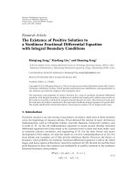
Figure 2: Average CCI power according to Δθ
(2)
i,k
.
α
(2)
i
(0 ≤ α
(2)
i
≤ 1) and θ
(2)
i
(−π ≤ θ
(2)
i
≤ π). Since
R
(2)
i
is a positive semidefinite Hermitian matrix, it can be
decomposed as [39]
R
(2)
i
= U
(2)
i
Λ
(2)
i
U
(2)∗
i
,(6)
where U
(2)
i
=
u
(2)
i,1
··· u
(2)
i,M
2
is an (M
2
× M
2
) unitary
matrix whose columns are the normalized eigenvectors of
R
(2)
i
,andΛ
(2)
i
is an (M
2
×M
2
) diagonal matrix whose diagonal
elements are
{λ
(2)
i,1
, , λ
(2)
i,M
2
},whereλ
(2)
i,1
≥··· ≥λ
(2)
i,M
2
≥ 0.
We de fine u
(2)
i,max
by the principal eigenvector corresponding
to the largest eigenvalue λ
(2)
i,1
of R
(2)
i
(i.e., u
(2)
i,1
= u
(2)
i,max
).
3. Previous Works
In this section, we briefly review relevant results which
motivate the design of interference mitigation scheme for
ease of description.
4 EURASIP Journal on Wireless Communications and Networking
λ
(2)
k,CCI,2
u
(2)
k,CCI,2
Δ
(2)
i,
k,2
= 0
Δ
(2)
i,
k,1
=
π
2
λ
(2)
k,CCI,1
u
(2)
k,CCI,1
M
2
= 2
u
(2)
i,max
(a)
λ
(2)
k,CCI,2
u
(2)
k,CCI,2
Nullspace of u
(2)
k,CCI,1
Δ
(2)
i,
k,2
/=
π
2
Δ
(2)
i,
k,3
/=
π
2
Δ
(2)
i,
k,1
=
π
2
λ
(2)
k,CCI,1
u
(2)
k,CCI,1
λ
(2)
k,CCI,3
u
(2)
k,CCI,3
M
2
= 3
u
(2)
i,max
(b)
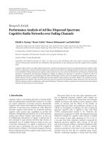
Figure 3: Design concept of the coordinated eigen-beamforming with geometrical interpretation.
θ = 0
θ
(2)
i
Δθ
(2)
i,
k
= π
RS
θ
(2)
k,CCI
θ = π
M
2
= 2
(a)
θ = 0
θ
(2)
i
θ
(2)
i
Δθ
(2)
i,
k
=
2π
3
Δθ
(2)
i,
k
=
2π
3
RS
θ
(2)
k,CCI
θ = π
M
2
= 3
(b)
Figure 4: Design concept of the coordinated eigen-beamforming with physical interpretation.
3.1. Eigen-Beamforming (Eig.BF). With the transmit correla-
tion information, the transmitter can determine the eigen-
beamforming vector by the principal eigenvector of the
transmit correlation matrix (i.e., w
(2)
k
= u
(2)
k,max
), yielding an
achievable rate bounded as [28]
R
(2)
k,Eig.BF
≤ log
2
1+γ
(2)
k
λ
(2)
k,max
,(7)
where
γ
(2)
k
(= P
BS
Γ
(2)
k
/σ
2
k
) denotes the average SNR of user
k. However, this scheme may experience the performance
degradation in interference-limited environments.
3.2. MMSE Interference Aware-Coordinated Beamforming
(MMSE-CBF). The MMSE-CBF designed for a two-cell two-
user MIMO cellular system can be applied to a two-user
two-hop MIMO relay system where users are equipped with
multiple receive antennas [15]. (Unlike our system model,
the MMSE-CBF assumes that each user has multiple receive
antennas since it jointly optimizes the transmit beamforming
and receive combining vector to maximize the SINR [15].
However, the design concept is applicable even when each
user has a single receive antenna.) In this case, the SINR of
user k can be represented as
SINR
(2)
k
=
γ
(2)
k
f
(2)∗
k
H
(2)∗
k
w
(2)
k
w
(2)∗
k
H
(2)
k
f
(2)
k
1+γ
(2)
k,CCI
f
(2)∗
k
H
(2)∗
k,CCI
w
(2)
i
w
(2)∗
i
H
(2)
k,CCI
f
(2)
k
=
γ
(2)
k
f
(2)∗
k
H
(2)∗
k
w
(2)
k
w
(2)∗
k
H
(2)
k
f
(2)
k
f
(2)∗
k
I
N
+ γ
(2)
k,CCI
H
(2)∗
k,CCI
w
(2)
i
w
(2)∗
i
H
(2)
k,CCI
f
(2)
k
,
(8)
where N is the number of receive antennas of each user, f
(2)
k
denotes an (N × 1) receive combining vector of user k,and
H
(2)
k
and H
(2)
k,CCI
denote an (M
1
× N) channel matrix from
the BS to user k andan(M
2
× N) CCI channel matrix from
the relay to user k,respectively.Equation(8) is known as a
Rayleigh quotient [40] and is maximized when f
(2)
k
(before
the normalization) is given by [41]
f
(2)
k
=
I
N
+ γ
(2)
k,CCI
H
(2)∗
k,CCI
w
(2)
i
w
(2)∗
i
H
(2)
k,CCI
−1
H
(2)∗
k
w
(2)
k
,
(9)
EURASIP Journal on Wireless Communications and Networking 5
Achievable rate
Power-saving
effect
2nd hop: R
(2)
i,C-Eig.BF
(P
RS
)
1st hop: R
(1)
i,C-Eig.BF
(P
BS
)
P
RS
P
RS,max
P
RS,opt
P
RS
Max-min solution:
R
(1)
i,C-Eig.BF
(P
BS
) = R
(2)
i,C-Eig.BF
(P
RS,opt
)
Figure 5: Design concept of the proposed power allocation scheme.
which is the principal singular vector of γ
(2)
k
H
(2)∗
k
w
(2)
k
w
(2)∗
k
×H
(2)
k
(I
N
+ γ
(2)
k,CCI
H
(2)∗
k,CCI
w
(2)
i
w
(2)∗
i
H
(2)
k,CCI
)
−1
. The correspond-
ing SINR and the achievable rate of user k are, respectively,
given by
SINR
(2)
k
= γ
(2)
k
w
(2)∗
k
H
(2)
k
×
I
N
+ γ
(2)
k,CCI
H
(2)∗
k,CCI
w
(2)
i
w
(2)∗
i
H
(2)
k,CCI
−1
H
(2)∗
k
w
(2)
k
,
R
(2)
k,MMSE-CBF
= log
2
1 + SINR
(2)
k
.
(10)
Given the receive combing vector f
(2)
k
, the transmit beam-
forming vector can be determined by
w
(2)
k
= v
max
⎧
⎪
⎨
⎪
⎩
⎛
⎝
H
(2)
i,CCI
H
(2)∗
i,CCI
+
1
γ
(2)
i,CCI
I
M
1
⎞
⎠
−1
H
(2)
k
H
(2)∗
k
⎫
⎪
⎬
⎪
⎭
,
(11)
where v
max
{A} is the principal singular vector of matrix A
and H
(2)
i,CCI
denotes an (M
1
×N) CCI channel matrix from the
BS to user i. However, the channel gain of H
(2)
i,CCI
is very small
due to large path loss and shadowing effect [2]. The transmit
beamforming and receive combining vector for user i can be
determined in a similar manner.
4. Proposed Coordinated Transmission
In this section, we design a coordinated transmission strategy
for CCI mitigation and power allocation in a correlated
two-user two-hop MIMO relay system. To this end, we first
investigate the statistical characteristics of the CCI, and then
describe the design concept for the CCI mitigation and
power allocation. Finally, we derive the performance of the
proposed scheme in terms of the achievable sum rate.
4.1. Statistical Characteristics of Cochannel Interference. In a
spatially correlated channel, the channel gain is statistically
concentrated on a few eigen-dimensions of the transmit cor-
relation matrix [29]. In this case, the eigen-beamforming is
known as the optimum beamforming strategy when a single
data stream is transmitted to the user [28]. When the eigen-
beamforming is applied to the relay (i.e., w
(2)
i
= u
(2)
i,max
),
the CCI power from the relay can be represented in terms
of the eigenvalue λ
(2)
k,CCI,m
and the inner-product between
u
(2)
i,max
and u
(2)
k,CCI,m
,whereλ
(2)
k,CCI,m
and u
(2)
k,CCI,m
denote the mth
eigenvalue and eigenvector of R
(2)
k,CCI
. The following theorem
provides the main result of this subsection.
Theorem 1. The average CCI from the relay with the use of
eigen-beamforming can be represented as
σ
(2)
k,CCI
= γ
(2)
k,CCI
M
2
m=1
λ
(2)
k,CCI,m
cos
2
Δ
(2)
i,k,m
, (12)
where Δ
(2)
i,k,m
(= (u
(2)
i,max
, u
(2)
k,CCI,m
)) denotes the angle difference
between u
(2)
i,max
and u
(2)
k,CCI,m
.
Proof. When w
(2)
k
= u
(2)
k,max
and w
(2)
i
= u
(2)
i,max
, the instanta-
neousSINRofuserk can be represented as
SINR
(2)
k
=
γ
(2)
k
h
(2)∗
k
u
(2)
k,max
2
1+γ
(2)
k,CCI
h
(2)∗
k,CCI
u
(2)
i,max
2
. (13)
It can easily be shown that the average CCI can be
represented as
σ
(2)
k,CCI
= γ
(2)
k,CCI
E
h
(2)∗
k,CCI
u
(2)
i,max
2
. (14)
Since h
(2)
k,CCI
= R
(2)/2
k,CCI
h
(2)
k,CCI
and E{
h
(2)∗
k,CCI
A
h
(2)
k,CCI
}=tr(A)
[40], (14)canberewrittenas
σ
(2)
k,CCI
= γ
(2)
k,CCI
tr
R
(2)
k,CCI
u
(2)
i,max
u
(2)∗
i,max
. (15)
It can be shown from R
(2)
k,CCI
= U
(2)
k,CCI
Λ
(2)
k,CCI
U
(2)∗
k,CCI
and
6 EURASIP Journal on Wireless Communications and Networking
tr(AB)
= tr(BA)[40] that
σ
(2)
k,CCI
= γ
(2)
k,CCI
tr
Λ
(2)
k,CCI
U
(2)∗
k,CCI
u
(2)
i,max
u
(2)∗
i,max
U
(2)
k,CCI
=
γ
(2)
k,CCI
M
2
m=1
λ
(2)
k,CCI,m
u
(2)∗
i,max
u
(2)
k,CCI,m
2
.
(16)
Since
|u
(2)∗
i,max
u
(2)
k,CCI,m
|=u
(2)
i,max
·u
(2)
k,CCI,m
cos (u
(2)
i,max
, u
(2)
k,CCI,m
)
(17)
and
u
(2)
i,max
=u
(2)
k,CCI,m
=1, thus, we can get
σ
(2)
k,CCI
= γ
(2)
k,CCI
M
2
m=1
λ
(2)
k,CCI,m
cos
2
u
(2)
i,max
, u
(2)
k,CCI,m
. (18)
This completes the proof of the theorem.
It can be seen that the CCI is associated with the
eigenvalue λ
(2)
k,CCI,m
and the angle difference Δ
(2)
i,k,m
between
u
(2)
i,max
and u
(2)
k,CCI,m
for m = 1,2, , M
2
. This implies that
the CCI can be controlled by adjusting λ
(2)
k,CCI,m
and Δ
(2)
i,k,m
in a statistical manner. In a highly correlated channel, the
CCI can be minimized (or maximized) by making Δ
(2)
i,k,max
(=
Δ
(2)
i,k,1
) = π/2(orΔ
(2)
i,k,max
= 0) since λ
(2)
k,CCI,m
= 0for
m
= 2, , M
2
. However, in a weakly correlated channel, even
when Δ
(2)
i,k,max
= π/2, the CCI cannot perfectly be eliminated
since u
(2)
i,max
and u
(2)
k,CCI,m
are not orthogonal to each other and
λ
(2)
k,CCI,m
is not zero for m = 2, , M
2
(i.e., Δ
(2)
i,k,m
/
=π/2and
λ
(2)
k,CCI,m
/
=0form = 2, , M
2
).
Corollary 2. When M
2
= 2, the average CCI can be simplified
to
σ
(2)
k,CCI
M
2
=2
= γ
(2)
k,CCI
1+α
(2)
k,CCI
cos Δθ
(2)
i,k
, (19)
where
σ
(2)
k,CCI
|
M
2
=2
denotes the CCI power when M
2
= 2 and
Δθ
(2)
i,k
(=|θ
(2)
i
− θ
(2)
k,CCI
|) denotes the phase difference between
the transmit correlation coefficients of h
(2)
i
and h
(2)
k,CCI
.
Proof. Since the eigenvalues and the corresponding eigenvec-
tors of R
(2)
k,CCI
for M
2
= 2 can be, respectively, represented as
[8]
Λ
(2)
k,CCI
=
⎡
⎣
λ
(2)
k,CCI,1
0
0 λ
(2)
k,CCI,2
⎤
⎦
=
⎡
⎣
1+α
(2)
k,CCI
0
01
− α
(2)
k,CCI
⎤
⎦
,
U
(2)
k,CCI
=
u
(2)
k,CCI,1
u
(2)
k,CCI,2
=
1
√
2
⎡
⎣
11
e
−jθ
(2)
k,CCI
−e
−jθ
(2)
k,CCI
⎤
⎦
,
(20)
(12)canberewrittenas
σ
(2)
k,CCI
M
2
=2
= γ
(2)
k,CCI
⎡
⎢
⎣
1+α
(2)
k,CCI
1
2
+
e
j|θ
(2)
i
−θ
(2)
k,CCI
|
2
2
+
1 −α
(2)
k,CCI
1
2
−
e
j|θ
(2)
i
−θ
(2)
k,CCI
|
2
2
⎤
⎥
⎦
.
(21)
Since e
ja
= cos a + j sin a for a real-valued a,thus,wecanget
σ
(2)
k,CCI
M
2
=2
= γ
(2)
k,CCI
1+α
(2)
k,CCI
cos
θ
(2)
i
− θ
(2)
k,CCI
. (22)
This completes the proof of the corollary.
It can be seen from Corollary 2 that the CCI depends
on the correlation amplitude α
(2)
k,CCI
and the phase difference
Δθ
(2)
i,k
between ρ
(2)
i
and ρ
(2)
k,CCI
. In a highly correlated channel
(i.e., α
(2)
k,CCI
= 1), the CCI can be minimized (or maximized)
when Δθ
(2)
i,k
= π (or Δθ
(2)
i,k
= 0). This implies that the
principal eigenvector u
(2)
i,max
and u
(2)
k,CCI,max
are orthogonal (or
parallel) to each other when Δθ
(2)
i,k
= π (or Δθ
(2)
i,k
= 0) [33].
Corollary 3. When M
2
= 3, the average CCI can be
represented as
σ
(2)
k,CCI
M
2
=3
= γ
(2)
k,CCI
3
m=1
λ
(2)
k,CCI,m
×
1+A
(2)
i,max,2
A
(2)
k,m,2
e
jΔθ
(2)
i,k
+ A
(2)
i,max,3
A
(2)
k,m,3
e
j2Δθ
(2)
i,k
2
,
(23)
where
A
(2)
i,max,2
=
α
(2)2
i
−
1 −λ
(2)
i,max
λ
(2)
i,max
α
(2)
i
,
A
(2)
i,max,3
=
1 −λ
(2)
i,max
2
− α
(2)2
i
λ
(2)
i,max
α
(2)2
i
,
A
(2)
k,m,2
=
α
(2)2
k,CCI
−
1 −λ
(2)
k,CCI,m
λ
(2)
k,CCI,m
α
(2)
k,CCI
,
A
(2)
k,m,3
=
1 −λ
(2)
k,CCI,m
2
− α
(2)2
k,CCI
λ
(2)
k,CCI,m
α
(2)2
k,CCI
.
(24)
Proof. The eigenvalues and the corresponding eigenvectors
of R
(2)
k,CCI
for M
2
= 3 can be, respectively, represented as (refer
to Appendix A)
EURASIP Journal on Wireless Communications and Networking 7
Λ
(2)
k,CCI
=
⎡
⎢
⎢
⎢
⎢
⎢
⎢
⎢
⎢
⎣
1+
α
(2)2
k,CCI
+
α
(2)4
k,CCI
+8α
(2)2
k,CCI
2
00
01
− α
(2)2
k,CCI
0
001+
α
(2)2
k,CCI
−
α
(2)4
k,CCI
+8α
(2)2
k,CCI
2
⎤
⎥
⎥
⎥
⎥
⎥
⎥
⎥
⎥
⎦
,
U
(2)
k,CCI
=
⎡
⎢
⎢
⎢
⎢
⎣
111
A
(2)
k,1,2
e
−jθ
(2)
k,CCI
A
(2)
k,2,2
e
−jθ
(2)
k,CCI
A
(2)
k,3,2
e
−jθ
(2)
k,CCI
A
(2)
k,1,3
e
−j2θ
(2)
k,CCI
A
(2)
k,2,3
e
−j2θ
(2)
k,CCI
A
(2)
k,3,3
e
−j2θ
(2)
k,CCI
⎤
⎥
⎥
⎥
⎥
⎦
.
(25)
It can be shown from (25) that (12)canberepresentedas
σ
(2)
k,CCI
M
2
=3
= γ
(2)
k,CCI
3
m=1
λ
(2)
k,CCI,m
×
1 A
(2)
i,max,2
e
jθ
(2)
i
A
(2)
i,max,3
e
j2θ
(2)
i
⎡
⎢
⎢
⎣
1
A
(2)
k,m,2
e
−jθ
(2)
k,CCI
A
(2)
k,m,3
e
−j2θ
(2)
k,CCI
⎤
⎥
⎥
⎦
2
= γ
(2)
k,CCI
3
m=1
λ
(2)
k,CCI,m
×
1+A
(2)
i,max,2
A
(2)
k,m,2
e
j|θ
(2)
i
−θ
(2)
k,CCI
|
+A
(2)
i,max,3
A
(2)
k,m,3
e
j2|θ
(2)
i
−θ
(2)
k,CCI
|
2
.
(26)
This completes the proof of the corollary.
Like Corollary 2, when M
2
= 3, the CCI depends on
α
(2)
k,CCI
and Δθ
(2)
i,k
between ρ
(2)
i
and ρ
(2)
k,CCI
. However, the phase
difference minimizing the CCI depends on the number of
antennas. Unlike M
2
= 2, the CCI can be minimized when
Δθ
(2)
i,k
= 2π/3forM
2
= 3. This implies that the principal
eigenvector u
(2)
i,max
and u
(2)
k,CCI,max
are orthogonal to each other
when Δθ
(2)
i,k
= 2π/3(refertoAppendix B for the proof).
Figure 2 depicts the average CCI power according to Δθ
(2)
i,k
when γ
(2)
k,CCI
= 10 dB, α
(2)
k,CCI
= 1.0,0.8, 0.6, and M
2
= 2, 3.
It can be seen that the CCI is minimized at Δθ
(2)
i,k
= π (or
Δθ
(2)
i,k
= 2π/3) when M
2
= 2(orM
2
= 3) as α
(2)
k,CCI
→ 1.
4.2. Design Concept of the Proposed Coordinated Eigen-
Beamforming. From Theorem 1, we can deduce the design
concept of the interference mitigation to minimize the CCI
in a statistical manner when the BS’s users and relay’s
users coexist. The main challenge is to determine how
to simultaneously schedule the BS’s user and the relay’s
user without major CCI effect. Based on Theorem 1, the
reasonable solution is to select a pair of users whose principal
eigenvectors u
(2)
i,max
and u
(2)
k,CCI,max
areorthogonaltoeach
other, that is,
Δ
(2)
i,
k,max
=
u
(2)
i,max
, u
(2)
k,CCI,max
=
π
2
, (27)
where
i and
k denote the indices of selected users. We
refer this criterion to the coordinated eigen-beamforming.
Figure 3 illustrates the design concept of the coordinated
eigen-beamforming with geometrical interpretation. It can
be shown that the principal eigenvector u
(2)
i,max
is orthogonal
to u
(2)
k,CCI,max
regardless of M
2
.However,theCCIpowerhas
adifferent behavior according to M
2
. When M
2
= 2, a
pair of users satisfying (27) can uniquely be determined
since u
(2)
k,CCI,2
is only orthogonal to the principal eigenvector
u
(2)
k,CCI,max
. This implies that the direction of u
(2)
i,max
should
be equal to that of u
(2)
k,CCI,2
(i.e., u
(2)
i,max
||u
(2)
k,CCI,2
), where ||
denotes a parallel relationship of two complex vectors. It can
be inferred that the CCI remains as much as λ
(2)
k,CCI,2
when
M
2
= 2. On the other hand, when M
2
= 3, there may
exist many pairs of users since the null-space of u
(2)
k,CCI,max
is two-dimensional. This implies that arbitrary vectors on
the null-space are always orthogonal to u
(2)
k,CCI,max
. In this
case, it is desirable for the relay to select a user with the
principal eigenvector minimally inducing the CCI power.
This is because u
(2)
i,max
and u
(2)
k,CCI,m
are not orthogonal to
each other for m
= 2, 3, and the CCI power remains as
3
m
=2
λ
(2)
k,CCI,m
cos
2
Δ
(2)
i,
k,m
, which varies according to the user
i
selected by the relay.
The proposed coordinated eigen-beamforming can be
fully characterized by the phase difference between ρ
(2)
i
and
ρ
(2)
k,CCI
.FromCorollaries2 and 3, it can be inferred that
the condition minimizing the CCI for M
2
antennas can be
determined as
Δθ
(2)
i,
k
=
2π
M
2
. (28)
(Although we do not consider the case for M
2
≥ 4dueto
intricate manipulation for the calculation of eigenvalues and
8 EURASIP Journal on Wireless Communications and Networking
−6
−4
−2
0
2
4
6
8
10
12
14
Average SINR of user k, SINR
k
(dB)
−10 −8 −6 −4 −20 2 4 6 8 10
Average SNR, γ
(2)
k
(dB)
M
1
= M
2
= 2
α
= 0.9
Δθ
(2)
i,k
= π
SINR
k,C-Eig.BF + opt. PA
SINR
k,C-Eig.BF + opt. PA
(approximation)
SINR
k,C-Eig.BF + max. PA
SINR
k,C-Eig.BF + max. PA
(approximation)
(a) Average SINR
0
0.5
1
1.5
2
2.5
3
3.5
4
4.5
5
Achievable rate of user k, R
k,C-Eig.BF
(bps/Hz)
−10 −8 −6 −4 −20 2 4 6 8 10
Average SNR, γ
(2)
k
(dB)
M
1
= M
2
= 2
α
= 0.9
Δθ
(2)
i,k
= π
R
k,C-Eig.BF + opt .PA
(upper bound)
R
k,C-Eig.BF + opt. PA
(approximation)
R
k,C-Eig.BF + opt. PA
(simulation)
R
k,C-Eig.BF + max. PA
(upper bound)
R
k,C-Eig.BF + max. PA
(approximation)
R
k,C-Eig.BF + max. PA
(simulation)
(b) Achievable rate
Figure 6: Performance of user k with the proposed scheme according to γ
(2)
k
.
eigenvectors of R
(2)
k,CCI
,(28) can straightforwardly be verified
by the manner described in Appendices A and B.)
Figure 4 illustrates physical meaning of the coordinated
eigen-beamforming. It can be seen that the CCI is minimized
when the phases of ρ
(2)
i
and ρ
(2)
k,CCI
are scattered as much as
possible.
4.3. Performance Analysis
Theorem 4. The average SINR of user
k with the use of the
proposed coordinated eigen-beamforming can be approximated
as
SINR
(2)
k,approx
=
γ
(2)
k
λ
(2)
k,max
1+σ
(2)
k,CCI
+
γ
(2)
k
λ
(2)
k,max
σ
(2)2
k,CCI
1+σ
(2)
k,CCI
3
, (29)
where
SINR
(2)
k,approx
is the approximated average SINR of user
k.
Proof. It can be shown from (13) that
SINR
(2)
k
= E
⎧
⎪
⎪
⎪
⎨
⎪
⎪
⎪
⎩
γ
(2)
k
h
(2)∗
k
u
(2)
k,max
2
1+γ
(2)
k,CCI
h
(2)∗
k,CCI
u
(2)
i,max
2
⎫
⎪
⎪
⎪
⎬
⎪
⎪
⎪
⎭
. (30)
Letting x
= γ
(2)
k
|h
(2)∗
k
u
(2)
k,max
|
2
and y = 1+
γ
(2)
k,CCI
|h
(2)∗
k,CCI
u
(2)
i,max
|
2
, it can be shown from multivariate
Taylor series expansion [42] that (30) can be approximated
as
SINR
(2)
k
= E
x
y
≈
E{x}
E
y
−
cov
x, y
E
y
2
+
E
{x}
E
y
3
var
y
SINR
(2)
k,approx
,
(31)
where var[y] denotes the variance of y and cov[x, y]denotes
the covariance of x and y. Since x and y are independent
random variables (i.e., cov[x, y]
= 0), (31) can further be
simplified to
SINR
(2)
k,approx
=
E{x}
E
y
+
E
{x}
E
y
3
var
y
. (32)
It can be shown from E
{x}=γ
(2)
k
λ
(2)
k,max
and E{y}=1+σ
(2)
k,CCI
that
SINR
(2)
k,approx
=
γ
(2)
k
λ
(2)
k,max
1+σ
(2)
k,CCI
+
γ
(2)
k
λ
(2)
k,max
1+σ
(2)
k,CCI
3
× E
γ
(2)2
k,CCI
h
(2)∗
k,CCI
u
(2)
i,max
4
− σ
(2)2
k,CCI
.
(33)
EURASIP Journal on Wireless Communications and Networking 9
2
2.5
0
3.5
4
4.5
5
Achievable sum-rate, R (bps/Hz)
0 20 40 60 80 100 120 140 160 180
Phase difference, Δθ
(2)
i,k
(degrees)
M
1
= M
2
= 2
α
= 0.9
γ
(2)
k
= 0dB
R
MMSE-CBF
+max.PA
R
C-Eig.BF
+opt.PA
R
C-Eig.BF
+max.PA
R
NC-Eig.BF
+max.PA
R
SVD/ZFBF
+max.PA
(a) M
2
= 2
2
2.5
3
3.5
4
4.5
5
5.5
Achievable sum-rate, R (bps/Hz)
0 20 40 60 80 100 120 140 160 180
Phase difference, Δθ
(2)
i,k
(degrees)
M
1
= M
2
= 3
α
= 0.9
γ
(2)
k
= 0dB
R
MMSE-CBF
+max.PA
R
C-Eig.BF
+opt.PA
R
C-Eig.BF
+max.PA
R
NC-Eig.BF
+max.PA
R
SVD/ZFBF
+max.PA
(b) M
2
= 3
Figure 7: Performance comparison according to Δθ
(2)
i,k
.
It can be shown after some mathematical manipulation that
[41]
SINR
(2)
k,approx
=
γ
(2)
k
λ
(2)
k,max
1+σ
(2)
k,CCI
+
γ
(2)
k
λ
(2)
k,max
σ
(2)2
k,CCI
1+σ
(2)
k,CCI
3
. (34)
This completes the proof of the theorem.
It can be seen from (12)and(29) that SINR
(2)
k,approx
depends on the eigenvalues λ
(2)
k,max
and λ
(2)
k,CCI,m
, and the angle
difference Δ
(2)
i,
k,m
. Although SINR
(2)
k,approx
depends on M
2
as
seen in Corollaries 2 and 3, it is maximized by selecting a
pair of users whose angle difference Δ
(2)
i,
k,max
is π/2inahighly
correlated channel.
Theorem 5. The proposed coordinated eigen-beamforming
can provide an achievable sum rate approximately represented
as
R
C-Eig.BF
≈ log
2
⎡
⎢
⎢
⎢
⎣
1+
γ
(2)
k
λ
(2)
k,max
1+σ
(2)
k,CCI
+
γ
(2)
k
λ
(2)
k,max
σ
(2)2
k,CCI
1+σ
(2)
k,CCI
3
⎤
⎥
⎥
⎥
⎦
+
1
2
min
log
2
1+γ
(1)
1
M
2
λ
(1)
1,max
,log
2
1+γ
(2)
i
λ
(2)
i,max
,
(35)
where
R
C-Eig.BF
denotes an approximated upper bound of the
achievable sum rate.
Proof. Using the Jensen’s inequality [39], the achievable sum
rate is bounded as
R
C-Eig.BF
= R
k
,C-Eig.BF
+ R
i
,C-Eig.BF
≤ log
2
⎛
⎜
⎜
⎜
⎝
1+E
⎧
⎪
⎪
⎪
⎨
⎪
⎪
⎪
⎩
γ
(2)
k
h
(2)∗
k
u
(2)
k,max
2
1+γ
(2)
k,CCI
h
(2)∗
k,CCI
u
(2)
i,max
2
⎫
⎪
⎪
⎪
⎬
⎪
⎪
⎪
⎭
⎞
⎟
⎟
⎟
⎠
+
1
2
min
log
2
1+E
γ
(1)
1
f
(1)∗
1
H
(1)∗
1
u
(1)
1,max
2
,
log
2
1+E
γ
(2)
i
h
(2)∗
i
u
(2)
i,max
2
R
C-Eig.BF
,
(36)
where R
k
,C-Eig.BF
and R
i
,C-Eig.BF
denote the achievable rate of
user
k and
i,respectively,
R
C-Eig.BF
denotes the upper bound
of the achievable sum rate, and f
(1)
1
denotes an (M
2
× 1)
combining vector of the relay. From (29), the upper bound
of user
k can be approximated as
R
k,C-Eig.BF
≈ log
2
⎡
⎢
⎢
⎢
⎣
1+
γ
(2)
k
λ
(2)
k,max
1+σ
(2)
k,CCI
+
γ
(2)
k
λ
(2)
k,max
σ
(2)2
k,CCI
1+σ
(2)
k,CCI
3
⎤
⎥
⎥
⎥
⎦
. (37)
Assuming that maximum ratio combining (MRC) is used at
the relay [15], the achievable rate of user
i is bounded as
R
i
,C-Eig.BF
≤
1
2
min
⎧
⎨
⎩
log
2
1+γ
(1)
1
tr
G
(1)
1
tr
R
(1)
1
u
(1)
1,max
u
(1)∗
1,max
,
log
2
1+γ
(2)
i
tr
R
(2)
i
u
(2)
i,max
u
(2)∗
i,max
⎫
⎬
⎭
.
(38)
10 EURASIP Journal on Wireless Communications and Networking
Since tr(G
(1)
1
) =
M
2
m=1
λ
(1)
1,m
= M
2
and tr(R
(1)
1
u
(1)
1,max
u
(1)∗
1,max
) =
λ
(1)
1,max
,(38)canberepresentedas
R
i,C-Eig.BF
≤
1
2
min
log
2
1+γ
(1)
1
M
2
λ
(1)
1,max
,log
2
1+γ
(2)
i
λ
(2)
i,max
.
(39)
Thus, it can be shown from (37)and(39) that
R
C-Eig.BF
≈ log
2
⎡
⎢
⎢
⎢
⎣
1+
γ
(2)
k
λ
(2)
k,max
1+σ
(2)
k,CCI
+
γ
(2)
k
λ
(2)
k,max
σ
(2)2
k,CCI
1+σ
(2)
k,CCI
3
⎤
⎥
⎥
⎥
⎦
+
1
2
min
log
2
1+γ
(1)
1
M
2
λ
(1)
1,max
,log
2
1+γ
(2)
i
λ
(2)
i,max
.
(40)
This completes the proof of the theorem.
It can be seen that the proposed coordinated eigen-
beamforming maximizes the achievable sum rate when
Δ
(2)
i,
k,max
= π/2 (i.e., yielding zero interference and large
beamforming gain) in a highly correlated channel.
4.4. Allocation of Transmit Power. Although the CCI can
effectively be controlled by adjusting the angle difference
between the principal eigenvectors of two users, it cannot
be minimized in an instantaneous sense. This issue can be
alleviated by allocating the relay transmit power as low as
possible since the CCI power is proportional to the relay
transmit power. However, the transmit power needs to be
allocated to maximize the minimum rate of two hops. It may
be desirable to allocate the transmit power considering the
CCI mitigation in a joint manner. The main goal is to allocate
the transmit power to reduce the CCI while maximizing the
achievable rate of the relay link.
Suppose that P
BS
≤ P
BS,max
and P
RS
≤ P
RS,max
since
the BS and relay are not geographically colocated [35],
where P
BS,max
and P
RS,max
denote the maximum power of
the BS and the relay, respectively, and that the transmit
power of the BS is given by P
BS
. Then, it is desirable to
determine the minimum transmit power of the relay to
achieve the rate of the first hop. Figure 5 illustrates the
concept of the proposed power allocation. When P
RS
=
P
RS,max
, the achievable rate of the relay link is determined
as R
(1)
i,C-Eig.BF
(P
BS
) since R
(1)
i,C-Eig.BF
(P
BS
) <R
(2)
i,C-Eig.BF
(P
RS,max
).
Thus, the transmit power of the relay can be determined by
the crossing point between the achievable rate of the first and
the second hop.
Theorem 6. Thetransmitpoweroftherelaycanbedetermined
w ith the consideration of CCI mitigation as
κ
opt
P
RS,opt
P
BS
=
Γ
(1)
1
σ
2
i
Γ
(2)
i
σ
2
1
M
2
λ
(1)
1,max
λ
(2)
i,max
, (41)
where κ
opt
(0 ≤ κ
opt
≤ P
RS,max
/P
BS
) is the transmit power ratio
between the BS and the relay.
Proof. By means of max-min optimization [35], the achiev-
able rate of the relay link can be maximized when
γ
(1)
1
M
2
λ
(1)
1,max
= γ
(2)
i
λ
(2)
i,max
. (42)
Since
γ
(1)
1
= P
BS
Γ
(1)
1
/σ
2
1
and γ
(2)
i
= P
RS
Γ
(2)
i
/σ
2
i
,(42)canbe
rewritten as
P
BS
Γ
(1)
1
σ
2
1
M
2
λ
(1)
1,max
=
P
RS
Γ
(2)
i
σ
2
i
λ
(2)
i,max
. (43)
After simple manipulation, it can be seen that
κ
opt
P
RS,opt
P
BS
=
Γ
(1)
1
σ
2
i
Γ
(2)
i
σ
2
1
M
2
λ
(1)
1,max
λ
(2)
i,max
. (44)
This completes the proof of the theorem.
It can be seen that the optimum power allocation is
associated with the path loss ratio Γ
(1)
1
/Γ
(2)
i
and the principal
eigenvalue ratio λ
(1)
1,max
/λ
(2)
i,max
between the two hops. In fact,
κ
opt
is inversely proportional to the achievable rate of each
hop. For example, as α
(2)
i
increases, R
(2)
i,C−Eig.BF
increases due
to large beamforming gain. In this case, it is desirable to
decrease κ
opt
to balance the rate between two-hops, or vice
versa.
4.5. Scheduling Complexity. We define the complexity mea-
surement as the number of the required user pairs and
compare the scheduling complexity for two user-scheduling
schemes; the proposed and the instantaneous CSI-based
user-scheduling schemes. For ease of description, we assume
that T
ST
and T
LT
denote the feedback period of short-term
and long-term CSI, respectively, where T
LT
is a multiple
of T
ST
. We also assume that the BS and the relay have an
equal number of users (i.e., K/2). To provide fair scheduling
opportunities to all K users during T
LT
, the proposed user-
scheduling scheme needs to consider (K/2)
2
cases at the
first scheduling instant and (K/2
− 1)
2
cases at the second
scheduling instant. Thus, it needs to consider S
LT
scheduling
cases during T
LT
,givenby
S
LT
=
T
LT
/T
Frame
D
LT
l=1
K
2
−
(
l
− 1
)
2
, (45)
where T
Frame
denotes the time duration of a single frame
and D
LT
denotes the portion allocated to a pair of users
during T
LT
, that is, D
LT
= 2T
LT
/KT
Frame
. On the other
hand, the instantaneous CSI-based user-scheduling scheme
needstoconsider(K/2)
2
cases to maximize the sum rate
per T
ST
(= T
Frame
). This is because it requires K signals for
EURASIP Journal on Wireless Communications and Networking 11
1.5
2
2.5
3
3.5
4
4.5
Achievable sum-rate, R (bps/Hz)
00.10.20.30.40.50.60.70.80.91
Correlation amplitude, α
M
1
= M
2
= 2
γ
(2)
k
= 0dB
Δθ
(2)
i,k
= π
R
MMSE-CBF
+max.PA
R
C-Eig.BF
+opt.PA
R
C-Eig.BF
+max.PA
R
NC-Eig.BF
+max.PA
R
SVD/ZFBF
+max.PA
(a) M
2
= 2
1.5
2
2.5
3
3.5
4
4.5
5
5.5
Achievable sum-rate, R (bps/Hz)
00.10.20.30.40.50.60.70.80.91
Correlation amplitude, α
M
1
= M
2
= 3
γ
(2)
k
= 0dB
Δθ
(2)
i,k
= 2π/3
R
MMSE-CBF
+max.PA
R
C-Eig.BF
+opt.PA
R
C-Eig.BF
+max.PA
R
NC-Eig.BF
+max.PA
R
SVD/ZFBF
+max.PA
(b) M
2
= 3
Figure 8: Performance comparison according to α.
0
1
2
3
4
5
6
7
8
9
Achievable sum-rate, R (bps/Hz)
−10 −8 −6 −4 −20 2 4 6 8 10
Average SNR, γ
(2)
k
(dB)
M
1
= M
2
= 2
α
= 0.9
Δθ
(2)
i,k
= π
R
MMSE-CBF
+max.PA
R
C-Eig.BF
+opt.PA
R
C-Eig.BF
+max.PA
R
NC-Eig.BF
+max.PA
R
SVD/ZFBF
+max.PA
(a) M
2
= 2
1
2
3
4
5
6
7
8
9
10
11
Achievable sum-rate, R (bps/Hz)
−10 −8 −6 −4 −20 2 4 6 8 10
Average SNR, γ
(2)
k
(dB)
M
1
= M
2
= 3
α
= 0.9
Δθ
(2)
i,k
= 2π/3
R
MMSE-CBF
+max.PA
R
C-Eig.BF
+opt.PA
R
C-Eig.BF
+max.PA
R
NC-Eig.BF
+max.PA
R
SVD/ZFBF
+max.PA
(b) M
2
= 3
Figure 9: Performance comparison according to γ
(2)
k
.
the feedback per each frame [43, 44]. It can be shown that
the instantaneous CSI-based user-scheduling scheme needs
to consider S
ST
scheduling cases during T
LT
,givenby
S
ST
=
T
LT
T
ST
K
2
2
. (46)
For example, when T
LT
= 300 ms, T
ST
= T
Frame
= 5ms,
and K
= 10, the proposed scheme needs to consider
S
LT
=
5
l=1
[5 −(l −1)]
2
= 55 scheduling cases. Here, D
LT
=
12. On the other hand, the instantaneous CSI-based scheme
needs to consider S
ST
= 60 · 5
2
= 1500 scheduling cases.
Ta bl e 1 depicts the scheduling complexity comparison
according to K when T
LT
= 300 ms and T
ST
= T
Frame
=
5 ms. It can be seen that the proposed scheme requires
lower scheduling complexity and smaller feedback signal
overhead than the instantaneous CSI-based scheme as K
increases.
12 EURASIP Journal on Wireless Communications and Networking
Table 1: Scheduling complexity according to K when T
LT
= 300 ms
and T
ST
= T
Frame
= 5ms.
Number of
users (K)
2 4 6 8 10 12
Instantaneous-
CSI based
scheduling
60 240 540 960 1500 2160
Proposed
scheduling
1 5 14 30 55 91
5. Performance Evaluation
The analytic results and performance of the proposed
coordinated eigen-beamforming with the optimum power
allocation (R
C-Eig.BF+Opt.PA
) and maximum power alloca-
tion (R
C-Eig.BF+Max.PA
) are verified by computer simula-
tion. For comparison, we consider three MIMO relay
transmission schemes; the MMSE-CBF with maximum
power allocation (R
MMSE-CBF+Max .PA
)[15], the noncoordi-
nated eigen-beamforming with maximum power allocation
(R
NC-Eig.BF+Max .PA
)[28], and the singular value decompo-
sition and ZF beamforming (SVD/ZFBF) with maximum
power allocation (R
SVD/ZFBF+Max .PA
)[11, 20]. (User k can
select the relay as its serving node through a cell selection
algorithm [45]. Then, our system can be converted into a
concatenated MIMO system comprising single-relay MIMO
channel for the first hop and MIMO broadcast channels
(MIMO-BC) for the second hop. In this case, the MIMO-
SVD and linear precoding such as ZF beamforming can
be employed to achieve the multiplexing gain, respectively
[11, 20, 37].) We assume that each link has the same
correlation amplitude (i.e., α
(1)
1
= α
(2)
i
= α
(2)
k
= α
(2)
k,CCI
= α),
and that the relay is placed at 0.7 km from the BS.
Figures 6(a) and 6(b), respectively, depict the average
SINR and the achievable rate of user k with the use of the
proposed scheme according to
γ
(2)
k
when M
1
= M
2
= 2,
α
= 0.9, and Δθ
(2)
i,k
= π.ItcanbeseenfromFigure 6(a)
that the approximated average SINR in (29) agrees well
with the real average SINR in (30), implying that the upper
bound of the achievable rate can be precisely approximated
to (37). Although the analytic and simulation results have
somewhat discrepancy in terms of the achievable rate due
to the Jensen’s loss (in a Rayleigh fading channel, the
Jensen’s loss is 0.83 bps/Hz at high SNR region [39]) (e.g.,
this gap is about 0.79 bps/Hz at
γ
(2)
k
= 10dB as seen in
Figure 6(b)), the analytic results still keep the behavior of
actual performance.
Figures 7(a) and 7(b), respectively, depict the achievable
sum rate of the proposed scheme according to Δθ
(2)
i,k
for M
1
=
M
2
= 2 and 3 when α = 0.9andγ
(2)
k
= 0dB.Itcanbeseen
that R
C-Eig.BF+Opt.PA
approaches to R
MMSE-CBF+Max .PA
when
Δθ
(2)
i,k
= π for M
2
= 2(orΔθ
(2)
i,k
= 2π/3forM
2
= 3). This
is mainly because the proposed scheme eliminates the most
of CCI by making the angle difference between u
(2)
i,max
and
u
(2)
k,CCI,max
orthogonal. It can also be seen that R
C-Eig.BF+Opt.PA
is
larger than R
C-Eig.BF+Max .PA
regardless of Δθ
(2)
i,k
, which means
that the CCI can also be reduced by minimizing the transmit
power of the relay. The sum rate gap between R
C-Eig.BF+Max .PA
and R
NC-Eig.BF+Max .PA
has a different behavior according to
M
2
. When M
2
= 2, the sum rate gap increases as Δθ
(2)
i,k
increases. On the other hand, when M
2
= 3, it somewhat
decreases for 2π/3 < Δθ
(2)
i,k
≤ π as Δθ
(2)
i,k
increases. This is
because the condition minimizing the CCI depends on M
2
as well as Δθ
(2)
i,k
. Although the SVD/ZFBF-based relay scheme
provides the multiplexing gain without the CCI effect [11],
its sum rate is somewhat limited due to the rank deficiency
of the first hop in a spatially correlated channel [37, 46].
Figure 8 depicts the achievable sum rate according to α
when M
1
= M
2
= 2, 3, Δθ
(2)
i,k
= 2π/M
2
and γ
(2)
k
= 0dB.Itcan
be seen that as α increases, the proposed scheme provides
the sum rate comparable to that of the MMSE-CBF. This
is mainly because the most of CCI is concentrated on the
direction of the principal eigenvector of R
(2)
k,CCI
in a highly
correlated channel. In this case, the most of CCI can be
eliminated by selecting users whose angle difference Δ
(2)
i,k,max
close to π/2. It can also be seen that R
C-Eig.BF+Opt.PA
is larger
than R
C-Eig.BF+Max.PA
regardless of α, and that R
C-Eig.BF+Max .PA
is nearly equal to R
NC-Eig.BF+Max .PA
when α is small. This
implies that the proposed power-allocation rule yields less
interference than the maximum one. The SVD/ZFBF-based
relay scheme outperforms the proposed scheme by having
more degrees of freedom in a weakly correlated channel.
This is mainly because the bottleneck effect due to the rank
deficiency is eased as α decreases.
Figure 9 depicts the achievable sum rate of the proposed
scheme according to
γ
(2)
k
when M
1
= M
2
= 2, 3, α = 0.9,
and Δθ
(2)
i,k
= 2π/M
2
. It can be seen that R
MMSE-CBF+Max .PA
is
always larger than R
C-Eig.BF+Opt.PA
regardless of γ
(2)
k
since it
can maximize the SINR by optimally handling the tradeoff
between the CCI cancellation and the noise suppression [19].
Nevertheless, it can be seen that the sum rate gap between
R
MMSE-CBF+Max .PA
and R
C-Eig.BF+Opt.PA
is very marginal in low
SNR region, (e.g., 0.08 bps/Hz gap (or 0.31bps/Hz gap) for
M
2
= 2(orM
2
= 3)). This implies that the proposed scheme
is quite effective near the cell boundary or coverage hole.
6. Conclusions
In this paper, we have considered the use of coordinated
transmission for the interference mitigation and power allo-
cation in a correlated two-user two-hop MIMO relay system.
We have analytically investigated the statistical characteristics
of CCI and the condition minimizing the CCI. Then, we have
considered coordinated transmission with the use of eigen-
beamforming with power allocation. We have shown that
the proposed scheme can maximize the achievable sum rate
when the principal eigenvectors of the transmit correlation
matrix of the intended and the CCI channel are orthogonal
to each other. The numerical results show that the proposed
scheme provides the maximum sum rate similar to that of
the MMSE-CBF, while reducing the complexity and feedback
signaling overhead. To extend this work, including multiple
antennas at each user is a topic for future work.
EURASIP Journal on Wireless Communications and Networking 13
Appendices
A. Derivation of Eigenvalues and
Eigenvectors of R When M
2
= 3
By the definition in [40], an eigenvector u of a transmit
correlation matrix R satisfies the equation
(
R
− λI
3
)
u
= 0,(A.1)
where user and time slot index are dropped for simple
notation. Since a necessary and sufficient condition for (A.1)
is
det
(
R
− λI
3
)
= 0, (A.2)
it can be explicitly expressed as
det
⎡
⎢
⎣
1 −λρ ρ
2
ρ
∗
1 −λρ
ρ
2∗
ρ
∗
1 −λ
⎤
⎥
⎦
=
0. (A.3)
Letting A
= 1 − λ and s = ρρ
∗
= α
2
,andaftersome
mathematical development, (A.3)canberewrittenas
A
3
−
s
2
+2s
A +2s
2
= 0. (A.4)
Since (A.4) has three solutions A
= (−s ±
√
s
2
+8s)/2ands,
the eigenvalues of R can be obtained as
λ
1
= 1+
α
2
+
√
α
4
+8α
2
2
, λ
2
= 1 −α
2
,
λ
3
= 1+
α
2
−
√
α
4
+8α
2
2
,
(A.5)
where λ
1
≥ λ
2
≥ λ
3
≥ 0. To get the eigenvector
corresponding to the mth eigenvalue of R, let us plug λ
m
back
into (A.2) and solve u
m
=
u
m,1
u
m,2
u
m,3
T
.Itcanbe
shown after some manipulation that the mth eigenvector u
m
can be determined as
u
m
=
1
α
2
−
(
1
− λ
m
)
λ
m
α
e
−jθ
(
1
− λ
m
)
2
− α
2
λ
m
α
2
e
−j2θ
T
.
(A.6)
This completes the proof of (25).
B. Orthogonal Property of Two Principal
Eigenvectors When M
2
= 3
Without the loss of generality, the time slot index is dropped
for simple notation. It can be shown from (A.6) that the
principal eigenvector of user i can be represented as
u
i,max
=
1
α
2
i
−
1 −λ
i,max
λ
i,max
α
i
e
−jθ
i
1 −λ
i,max
2
− α
2
i
λ
i,max
α
2
i
e
−j2θ
i
T
.
(B.1)
From [40], we have
cos
u
i,max
, u
k,CCI,max
=
u
∗
i,max
u
k,CCI,max
u
i,max
·
u
k,CCI,max
=
1+
α
2
i
−
1−λ
i,max
λ
i,max
α
i
α
2
k,CCI
−
1−λ
k,CCI,max
λ
k,CCI,max
α
k,CCI
e
j|θ
i
−θ
k,CCI
|
+
1−λ
i,max
2
−α
2
i
λ
i,max
α
2
i
1−λ
k,CCI,max
2
−α
2
k,CCI
λ
k,CCI,max
α
2
k,CCI
e
j2|θ
i
−θ
k,CCI
|
u
i,max
·
u
k,CCI,max
.
(B.2)
By letting
A
=
α
2
i
−
1 −λ
i,max
λ
i,max
α
i
α
2
k,CCI
−
1 −λ
k,CCI,max
λ
k,CCI,max
α
k,CCI
,
B
=
1 −λ
i,max
2
− α
2
i
λ
i,max
α
2
i
1 −λ
k,CCI,max
2
− α
2
k,CCI
λ
k,CCI,max
α
2
k,CCI
,
(B.3)
(B.2)canberewrittenas
cos
u
i,max
, u
k,CCI,max
=
1+Ae
j|θ
i
−θ
k,CCI
|
+ Be
j2|θ
i
−θ
k,CCI
|
u
i,max
·
u
k,CCI,max
=
1+A
2
+ B
2
+2A
(
1+B
)
cos|C | +2B cos 2|C|
u
i,max
·
u
k,CCI,max
,
(B.4)
where C denotes θ
i
− θ
k,CCI
,whichyields
u
i,max
, u
k,CCI,max
=
cos
−1
1+A
2
+B
2
+2A
(
1+B
)
cos|C|+2B cos 2|C|
u
i,max
·
u
k,CCI,max
.
(B.5)
Since A, B
→ 1asα
i
, α
k,CCI
→ 1, it can be shown that
u
i,max
, u
k,CCI,max
=
cos
−1
⎛
⎝
3+4cos
θ
i
− θ
k,CCI
+2cos2
θ
i
− θ
k,CCI
u
i,max
·
u
k,CCI,max
⎞
⎠
.
(B.6)
When
|θ
i
− θ
k,CCI
|=2π/3, we have (u
i,max
, u
k,CCI,max
) =
π/2.
Acknowledgment
This paper was supported by the National Research Founda-
tion of Korea (NRF) Grant funded by the Korea government
(MEST) (2009-0083789).
14 EURASIP Journal on Wireless Communications and Networking
References
[1] T. Cover and A. E. Gamal, “Capacity theorems for the relay
channel,” IEEE Transactions on Information Theory, vol. 25, no.
5, pp. 572–584, 1979.
[2] R. Pabst, B. H. Walke, D. C. Schultz et al., “Relay-based
deployment concepts for wireless and mobile broadband
radio,” IEEE Communications Magazine, vol. 42, no. 9, pp. 80–
89, 2004.
[3] H.Hu,H.Yanikomeroglu,D.D.Falconer,andS.Periyalwar,
“Range extension without capacity penalty in cellular net-
works with digital fixed relays,” in Proceedings of the IEEE
Global Telecommunications Conference (GLOBECOM ’04), vol.
5, pp. 3053–3058, Dallas, Tex, USA, November 2004.
[4] S. W. Peters, A. Y. Panah, K. T. Truong, and R. W. Heath
jr., “Relay architectures for 3GPP LTE-advanced,” EURASIP
Journal on Wireless Communications and Networking, vol.
2009, Article ID 618787, 14 pages, 2009.
[5] G. J. Foschini and M. J. Gans, “On the limits of wireless com-
munications in a fading environment when using multiple
antennas,” Wireless Personal Communications,vol.6,no.3,pp.
311–335, 1998.
[6] I. E. Telatar, “Capacity of multi-antenna Gaussian channels,”
European Transactions on Telecommunications,vol.10,no.6,
pp. 585–595, 1999.
[7] A. Goldsmith, S. A. Jafar, N. Jindal, and S. Vishwanath,
“Capacity limits of MIMO channels,” IEEE Journal on Selected
Areas in Communications, vol. 21, no. 5, pp. 684–702, 2003.
[8] G. Caire and S. Shamai, “On the achievable throughput of a
multiantenna Gaussian broadcast channel,” IEEE Transactions
on Information Theory, vol. 49, no. 7, pp. 1691–1706, 2003.
[9] B. Wang, J. Zhang, and A. Høst-Madsen, “On the capacity
of MIMO relay channels,” IEEE Transactions on Information
Theory, vol. 51, no. 1, pp. 29–43, 2005.
[10] C. K. Lo, S. Vishwanath, and R. W. Heath Jr., “Sum-
rate bounds for MIMO relay channels using precoding,” in
Proceedings of the IEEE Global Telecommunications Conference
(GLOBECOM ’05), pp. 1172–1176, St. Louis, Mo, USA,
November 2005.
[11] C B. Chae, T. Tang, R. W. Heath Jr., and S. Cho, “MIMO
relaying with linear processing for multiuser transmission in
fixed relay networks,” IEEE Transactions on Signal Processing,
vol. 56, no. 2, pp. 727–738, 2008.
[12] T. Han and K. Kobayashi, “A new achievable rate region for
the interference channel,” IEEE Transactions on Information
Theory, vol. 27, no. 1, pp. 49–60, 1981.
[13] R. H. Etkin, D. N. C. Tse, and H. Wang, “Gaussian interference
channel capacity to within one bit,” IEEE Transactions on
Information Theory, vol. 54, no. 12, pp. 5534–5562, 2008.
[14] G. Bresler and D. Tse, “The two-user Gaussian interference
channel: a deterministic view,” European Transactions on
Telecommunications, vol. 19, no. 4, pp. 333–354, 2008.
[15]C.B.Chae,I.S.Hwang,R.W.HeathJr.,andV.
Tarok, “Interference aware-coordinated beamforming
system in a two-cell environment,” submitted to
IEEE Journal of Selected Areas in Communications,
/>[16] K. Gomadam, V. R. Cadambe, and S. A. Jafar, “Approach-
ing the capacity of wireless networks through distributed
interference alignment,” in Proceedings of the IEEE Global
Telecommunications Conference (GLOBECOM ’08), vol. 19, pp.
1–6, New Orleans, La, USA, November 2008.
[17] C B. Chae, D. Mazzarese, N. Jindal, and R. W. Heath Jr.,
“Coordinated beamforming with limited feedback in the
MIMO broadcast channel,” IEEE Journal on Selected Areas in
Communications, vol. 26, no. 8, pp. 1505–1515, 2008.
[18]C.B.Peel,B.M.Hochwald,andA.L.Swindlehurst,“A
vector-perturbation technique for near-capacity multiantenna
multiuser communication—part I: channel inversion and
regularization,” IEEE Transactions on Communications, vol. 53,
no. 1, pp. 195–202, 2005.
[19] J. Joung and Y. Lee, “Regularized channel diagonalization
for multiuser MIMO downlink using a modified MMSE
criterion,” IEEE Transactions on Signal Processing, vol. 55, no.
4, pp. 1573–1579, 2007.
[20] T. Yoo and A. Goldsmith, “On the optimality of multiantenna
broadcast scheduling using zero-forcing beamforming,” IEEE
Journal on Selected Areas in Communications,vol.24,no.3,pp.
528–541, 2006.
[21] Q. Ma and C. Tepedelenlio
ˇ
glu, “Practical multiuser diversity
with outdated channel feedback,” IEEE Transactions on Vehic-
ular Technology, vol. 54, no. 4, pp. 1334–1345, 2005.
[22] M. Nicoli, O. Simeone, and U. Spagnolini, “Multislot esti-
mation of frequency-selective fast-varying channels,” IEEE
Transactions on Communications, vol. 51, no. 8, pp. 1337–
1347, 2003.
[23] P. Lombardo, G. Fedele, and M. M. Rao, “MRC performance
for binary signals in Nakagami fading with general branch
correlation,” IEEE Transactions on Communications, vol. 47,
no. 1, pp. 44–52, 1999.
[24] S. L. Loyka, “Channel capacity of MIMO architecture using
the exponential correlation matrix,” IEEE Communications
Letters, vol. 5, no. 9, pp. 369–371, 2001.
[25] A. F. Naguib, Adaptive antennas for CDMA wireless network,
Ph.D. dissertation, Stanford University, Stanford, Calif, USA,
1996.
[26] K.I.Pedersen,J.B.Andersen,J.P.Kermoal,andP.Mogensen,
“A stochastic multiple-input-multiple-output radio channel
model for evaluation of space-time coding algorithms,” in
Proceedings of the IEEE Vehicular Technology Conference, vol.
2, pp. 893–897, Boston, Mass, USA, October 2008.
[27] 3GPP, “Spatial channel model for multiple input multiple out-
put (MIMO) simulations,” Tech. Rep. TR 25.996, September
2003.
[28] C. Brunner, W. Utschick, and J. A. Nossek, “Exploiting the
short-term and long-term channel properties in space and
time: eigenbeamforming concepts for the BS in WCDMA,”
European Transactions on Telecommunications, vol. 12, no. 5,
pp. 365–378, 2001.
[29] M. T. Ivrla
ˇ
c, W. Utschick, and J. A. Nossek, “Fading cor-
relations in wireless MIMO communication systems,” IEEE
Journal on Selected Areas in Communications,vol.21,no.5,pp.
819–828, 2003.
[30] S. Vishwanath, N. Jindal, and A. Goldsmith, “Duality,
achievable rates, and sum-rate capacity of Gaussian MIMO
broadcast channels,” IEEE Transactions on Information Theory,
vol. 49, no. 10, pp. 2658–2668, 2003.
[31] H. Weingarten, Y. Steinberg, and S. Shamai, “The capacity
region of the Gaussian multiple-input multiple-output broad-
cast channel,” IEEE Transactions on Information Theory, vol.
52, no. 9, pp. 3936–3964, 2006.
[32] T. Y. Al-naffouri, M. Sharif, and B. Hassibi, “How much
does transmit correlation affect the sum-rate scaling of
MIMO Gaussian broadcast channels?” IEEE Transactions on
Communications, vol. 57, no. 2, pp. 562–572, 2009.
[33]J W.Lee,J Y.Ko,andY H.Lee,“Effect of transmit
correlation on the sum-rate capacity of two-user broadcast
EURASIP Journal on Wireless Communications and Networking 15
channels,” IEEE Transactions on Communications, vol. 57, no.
9, pp. 2597–2599, 2009.
[34] Y. Liang and V. V. Veeravalli, “Gaussian orthogonal relay
channels: optimal resource allocation and capacity,” IEEE
Transactions on Information Theory, vol. 51, no. 9, pp. 3284–
3289, 2005.
[35] Y. Liang, V. V. Veeravalli, and H. V. Poor, “Resource allocation
for wireless fading relay channels: max-min solution,” IEEE
Transactions on Information Theory, vol. 53, no. 10, pp. 3432–
3453, 2007.
[36] M. Dohler, A. Gkelias, and H. Aghvami, “2-hop distributed
MIMO communication system,” Electronics Letters, vol. 39, no.
18, pp. 1350–1351, 2003.
[37] A. Paulraj, R. Nabar, and D. Gore, Introduction to Space-
Time Wireless Communications, Cambridge University Press,
Cambridge, UK, 2003.
[38] W. C. Jakes, MicrowaveMobileCommunications, Bee Press,
New York, NY, USA, 1993.
[39] D. Tse and P. Vishwanath, Fundamentals of Wireless Communi-
cation, Cambridge University Press, Cambridge, UK, 2005.
[40] S. Gilbert, Linear Algebra and Its Applications,
BROOKS/COLE, Pacific Grove, Calif, USA, 1998.
[41] R. A. Horn and C. R. Johnson, Matrix Analysis, University of
Cambridge Press, New York, NY, USA, 4th edition, 1990.
[42] V. G. Jenson and G. V. Jeffreys, Mathematical Methods in
Chemical Engineering, Academic Press, New York, NY, USA,
1963.
[43] D. Gesbert and M S. Alouini, “How much feedback is
multi-user diversity really worth?” in Proceedings of the IEEE
International Conference on Communications, pp. 234–238,
Paris, France, June 2004.
[44] T. Tang, R. W. Heath Jr., S. Cho, and S. Yun, “Opportunistic
feedback for multiuser MIMO systems with linear receivers,”
IEEE Transactions on Communications, vol. 55, no. 5, pp. 1020–
1032, 2007.
[45] K W. Lee, J Y. Ko, and Y H. Lee, “Fast cell site selection
with interference avoidance in packet based OFDM cellular
systems,” in Proceedings of the IEEE Global Telecommunications
Conference (GLOBECOM ’06), pp. 1–5, San Francisco, Calif,
USA, October 2006.
[46] D. W. Browne, M. W. Browne, and M. P. Fitz, “Singular value
decomposition of correlated MIMO channels,” in Proceedings
of the IEEE Global Telecommunications Conference (GLOBE-
COM ’06), pp. 1–6, San Francisco, Calif, USA, October 2006.