Báo cáo hóa học: "Research Article Particle Swarm Optimization for Adaptive Resource Allocation in Communication Networks" pptx
Bạn đang xem bản rút gọn của tài liệu. Xem và tải ngay bản đầy đủ của tài liệu tại đây (1.49 MB, 13 trang )
Hindawi Publishing Corporation
EURASIP Journal on Wireless Communications and Networking
Volume 2010, Article ID 465632, 13 pages
doi:10.1155/2010/465632
Research Article
Particle Swarm Optimizat ion for Adaptive Resource Allocation in
Communication Networks
Shahin Gheitanchi, Falah Ali, and E lias Stipidis
School of Engineering & Design, University of Sussex, Falmer, Brighton BN1 9QT, UK
Correspondence should be addressed to Falah Ali,
Received 13 January 2010; Revised 25 May 2010; Accepted 6 July 2010
Academic Editor: Hyunggon Park
Copyright © 2010 Shahin Gheitanchi et al. This is an open access article distributed under the Creative Commons Attribution
License, which permits unrestricted use, distribution, and reproduction in any medium, provided the original work is properly
cited.
A generalized model of particle swarm optimization (PSO) technique is proposed as a low complexity method for adaptive
centralized and distributed resource allocation in communication networks. The proposed model is applied to adaptive
multicarrier cooperative communications (MCCC) technique which utilizes the subcarriers in deep fade using a relay node in
order to improve the bandwidth efficiency. Centralized PSO, based on virtual particles (VPs), is introduced for single layer and
cross-layer subcarrier allocation to improve the bit error rate performance in multipath frequency selective fading channels. In
the single layer strategy, the subcarr iers are allocated based on the channel gains. In the cross-layer strategy, the subcarriers are
allocated based on a joint measure of channel gains and distance provided by the physical layer and network layer to mitigate the
effect of path loss. The concept of training particles in distributed PSO is proposed and then is applied for relay node selection. The
computational complexity and traffic of the proposed techniques are investigated, and it is shown that using PSO for subcarrier
allocation has a lower complexity than the techniques in the literature. Significant reduction in the t rafficoverheadofPSOis
demonstrated when using trained particles in distributed optimizations.
1. Introduction
Particle swarm optimization (PSO) [1] is an optimization
technique inspired from the interaction between swarm
members that requires no supervision or prior knowledge
and is based on primitive instincts. PSO technique has been
applied to different layers of the open system interconnection
(OSI) multilayer reference model which is designed for
standard separation of network functionalities in commu-
nication systems [2]. In the OSI reference model, each layer
exchanges data with adjacent layers in a node whilst allowing
communication between peer layers with other nodes using a
stack of protocols. To increase the efficiency and performance
of each layer, the PSO technique has been utilized for single
layer optimizations [ 3–9]. Recently, PSO has been applied
for physical layer optimizations [3, 4]. For example in [4],
PSO with virtual particles (VPs) is applied for resource
allocation in orthogonal frequency division multiple access
(OFDMA) where the subcarriers with the higher channel
gains are adaptively allocated to users. In the literature, PSO
has mostly been used for clustering of nodes in ad hoc
networks aiming to minimize energy consumption [6–8]. In
[6] the authors have applied PSO to cluster head selection,
and in [7] it has been used for distance-based clustering
of wireless sensor networks. Furthermore, in [8]PSOis
employed to optimize the cost and coverage of clustering
in mobile ad hoc networks. Many other applications for
PSO in communications such as IP multicasting and channel
assignment only have been mentioned in [9]. Using PSO in
ad hoc network optimization increases flexibility, adaptation
and robustness. While this optimization method is simple,
it introduces enormous traffic and computation overhead to
the network.
In this paper, a generalized PSO model for adaptive
resource allocation in communication networks is pro-
posed which can be applied for single layer and cross-
layer optimizations. It consists of PSO with VPs [4]for
centralized scenarios and trained PSO (TPSO) [5]for
distributed scenarios. The proposed model is applied to the
adaptive multicarrier cooperative communication (MCCC)
2 EURASIP Journal on Wireless Communications and Networking
OSI layers
PSO-based
layer
(a)
OSI layers
PSO-based
layer
(b)
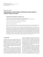
Figure 1: (a) Network model for centralized PSO in a single node. (b) Network model for distributed PSO in an ad hoc network using
different nodes in the system.
technique [10] that utilizes a relay node to use the subcarriers
with low channel gain to improve bandwidth efficiency. In
a single layer str ategy, the centralized PSO is used in the
physical layer to reduce the computational complexity of
subcarrier allocation. In a cross-layer strategy, centralized
PSO is applied for subcarrier allocation based on a joint
measure of node distances and channel gains to mitigate
the effect of path loss. Distributed TPSO is employed for
adaptive relay node selection in MCCC to reduce the tr a ffic
overhead.
In the rest of this paper, in Section 2,scopeofPSOin
communication networks is introduced. Next, in Section 3,a
generalized PSO model for adaptive communication systems
is proposed. In Section 4, the adaptive MCCC system model
is explained. In Section 5, centralized and distributed PSO-
aided resource allocation techniques in adaptive MCCC are
introduced. In Section 6, the computational complexity and
traffic overhead of the proposed techniques are investigated.
In Section 7, the bit error rate performance is investigated by
simulation. Finally, the paper is concluded.
2. Scope of PSO in Communication Networks
Based on the execution location of PSO algorithm, the opti-
mization process is divided to centralized and distributed. In
centralized PSO, the optimization is performed in a single
node of a network. However, depending on the objective and
the method of optimization, PSO process can r un in more
than one node and can be distributed over multiple nodes
within the network. Figure 1(a) shows a centralized PSO for
single node optimization, and Figure 1(b) shows distributed
PSO over multinodes in an ad hoc network.
In many optimization processes the data is collected
from more than one layer to achieve the objective of
the process [11]. These processes are referred to as cross-
layer optimizations. The centralized PSO for cross-layer
optimization in a single node is divided to three categories
as shown in Figure 2 for seven layer OSI network model.
(1) The optimization is performed using one PSO
process in a single layer, and the needed data for
optimization is provided by one or many other layers.
(2) The optimization is performed in multi-PSO pro-
cesses in different layers. In this case, all the involved
layers of the node interact with each other to share
the data and the processing load.
(3) The optimization is performed in one PSO process in
an extralayer dedicated to the optimization process.
This layer is responsible for the collection and
processing of the data from one or more layers of a
node.
Furthermore, the cross-layer optimization process can also
be centralized in one node or be distributed over multiple
nodes.
3. Generalized PSO Model
In this section, a generalized model of PSO is proposed which
will be utilized for adaptive resource allocation in MCCC
technique. In PSO, individual members of swarm are called
particles. Each particle keeps track of its coordinates in the
problem space which are associated with the best solution
(fitness) it has achieved so far. The best solution found
by a particle is called the personal best (PB). Additionally
each particle has knowledge of the best solution found by
nearby particles, called the global best (GB). Particles act
individually under the same principle: accelerate toward the
PB and GB locations while constantly checking the fitness
value of current location. In the proposed generalized PSO
model, P particles with unique particle IDs (PIDs) are ran-
domly distributed over solution space. The solution space,
S, is the set of all possible solutions for the optimization
problem. Depending on the problem, the solution space can
have M number of dimensions where the mth dimension,
S
m
, contains N elements, s
m
n
. Each particle is capable of
measuring the suitability of solutions by using the fitness
function f (S
1
, S
2
, , S
M
). All particles use a unique fitness
EURASIP Journal on Wireless Communications and Networking 3
Layer 1 Layer 1 Layer 1
Layer 7 Layer 7 Layer 7
Layer n Layer n Layer n
Layer n
− 1Layern − 1Layern − 1
Layer n + 1 Layer n + 1 Layer n +1
PSO
PSO
PSO
PSO
PSO
Category 1 Category 2 Category 3
Optimization layer
.
.
.
.
.
.
.
.
.
.
.
.
.
.
.
.
.
.
Figure 2: Centralized PSO for cross-layer optimization scenarios in a single node.
function to be able to compare the suitability of the solutions.
PSO is flexible in that the optimization objective can be
changed by modifying the fitness function. It should be
noted that modification to the fitness function can affect
the overall computational complexity. A mathematically
complex function for calculating the fitness value has a
greater computational requirement in the execution envi-
ronment than a simple function. Therefore, for efficiency
purposes utilization of a low complexity fitness function is
recommended. The objective of the optimization is to find
elements in solution spaces that maximize the fitness,
S =
(s
1
, s
1
, , s
M
), described as
S = Argmax f
S
1
, S
2
, , S
M
. (1)
Assuming synchronized timing and identical speed
among the particles, the optimization is performed during
Γ iterations. At each iteration, the particles compare the
PB and the GB to choose a direction indep endently based
on the distance differences from current location to the
GB and to the PB locations. To have a more practical
model in resource limited communication networks, the
particle decision making mechanism of the proposed model
is simplified compared to the original PSO described in [1].
The physical distance between two locations, (s
1
1
, s
1
2
)and
(s
2
1
, s
2
2
)forM = 2isgivenby
d
=
s
2
1
− s
1
1
2
+
s
2
2
− s
1
2
2
. (2)
Also, particles consider nostalgia, w
n
, and social influ-
ence, w
s
, for deciding their directions. The weights, w
n
and
w
s
, describe the importance of nostalgia and social influence
for particles, where w
n
+ w
s
= 1. We define the following
expression for deciding the direction
direction is towards
⎧
⎨
⎩
PB if
(
w
n
d
LB
− w
s
d
GB
)
≤ 0,
GB if
(
w
n
d
LB
− w
s
d
GB
)
> 0,
(3)
(1) Initialize and distribute particles
(2) Loop while not (termination criteria (1) and (2))
(3) For each particle:
(4) If (PB > GB)
(5) Replace GB and PB
(6) Calculate PB
(7) Decide the direction towards PB or GB
(8) Move to new position
(9) End of for
(10) End of loop
Algorithm 1: Generalized PSO algorithm.
where d
LB
is the distance from the current location to the
PB and d
GB
is the distance from the current location to
the GB. After calculating the direction, the particle moves
toward the decided destination which is either PB or GB.
During the optimization process, the GB is updated and
broadcasted in the network when a solution with higher
fitness value is found by a particle. After Γ iterations the
particles gather ( or converge) on the location with the
highest fitness value and the algorithm terminates. This is
referred to as termination criteria (1). The value of GB
is considered as the solution of the optimization problem.
Algorithm 1 shows the generalized PSO algorithm.
It should be noted that, as a result of heuristic nature of
PSO, if the same GB value is found in more than one location
the particles may not converge over a single solution space.
To avoid probability of an infinite loop, in cases of equal GB
values, and to allow management of the execution time, a
maximum iteration number, Γ
max
, is set. When the process
is stopped by reaching Γ
max
, called termination criteria (2),
the GB with highest population of particles is chosen as the
solution. Terminating the process in this way may lead to
suboptimal results. Therefore, it is desired to increase the
chance of reaching the optimal solution during a fixed period
of time.
4 EURASIP Journal on Wireless Communications and Networking
BPSK
modulator
BPSK
modulator
Sub-carrier
mapping
Sub-carrier
mapping
Add
CP
Add
CP
IFFT
IFFT
Remove
CP
Sub-carrier
demapping
BPSK
demodulator
FFT
Remove
CP
Sub-carrier
demapping
BPSK
demodulator
FFT
.
.
.
.
.
.
.
.
.
.
.
.
Data
source
(R)elay
(T)ransmitter
(D)estination
H
TR
H
RD
Multiple access
channel
H
TD
Z
R
Z
D
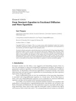
Figure 3: Block diagram of three cooperating nodes (transmitter-relay-destination) using orthogonal multicarrier modulation.
Increasing the number of particles, P, enables the
algorithm to inspect the entire solution space before reaching
Γ
max
.BothP and Γ
max
, are set during offline (by simulation)
or online (after implementation) calibration process. The
calibration process is performed in a solution space where the
GB value is known. The process starts by setting P and Γ
max
to a relatively large number in comparison to the number
elements in solution space and then adjusting the parameters
to reach a point where the algorithm converges over the GB
in the given iteration time. T he calibration process could be
performed in intervals according to the dynamic nature of
the solution space.
4. Adaptive MCCC Technique
Multicarrier communication is a well-known technique to
achieve high performance in frequency selective channels
[12]. It has been shown by adaptively allocating the subcar-
riers to the users with higher channel gains, the bit error rate
performance of multicarr ier communication is improved
[13, 14]. However, the subcarriers with lower channel gains
are discarded which results in reduction of spectral efficiency.
To i mprove s p ectral e fficiency, the MCCC technique has been
proposed [10] that utilizes a higher number of subcarriers
by means of cooperating with other nodes and utilizing
them as a relay. In the following, the MCCC system model
is described for three-node scenario to demonstrate benefit
of employing PSO in adaptive resource allocation process.
In the present study, only a single relay node is utilized to
clearly illustrate the proposing idea of using PSO and the
gain that can be achieved with low complexity. In principle
the system could be extended to include more relays but
at the cost of complexity. In the system model of adaptive
MCCC, an ad hoc network which consists of autonomous
nodes that are randomly distributed in a two-dimensional
landscape is considered. It is assumed that all nodes are in
radio coverage range of each other and support multiple
connections. In the network layer, the nodes use the shortest
path routing algorithm. At each instance, a transmitter
node communicates to the destination using cooperative
communication by transmitting the data through a relay
node.
In the physical layer, the nodes use multicarrier mod-
ulation over N orthogonal subcarriers. The number of
subcarriers used for the transmitter-relay (TR), transmitter-
destination (TD), and relay-destination (RD) links are N
TR
,
N
TD
,andN
RD
,respectively,whereN
TR
+ N
TD
≤ N and
N
TR
= N
RD
. T he subcarriers are exclusively allocated to each
node.
The objective of cooperation is to maximize the band-
width efficiency by utilizing the adaptively allocated subcar-
riers to the transmitter and relay nodes. The cooperation
protocol consists of two time slots. In time slot one (TS1),
the transmitter node allocates N
TR
and N
TD
subcarriers for
TR and TD links and sends different data to the relay and
destination nodes. In time slot two (TS2), the relay node
allocates N
RD
subcarriers to the RD link and sends the data
received from the transmitter node in TS1 to the destination
node where N
RD
= N
TR
. It is assumed that the nodes are fully
synchronized and aware of the cooperative protocol. Next,
we describe in more detail the MCCC transmission shown in
Figure 3 employing the cooperation protocol in Tabl e 1.
Time Slot 1. At the physical layer, the transmitter and relay
nodes have binary modulated data (
−1, +1), using binary
phase shift keying (BPSK), which are mapped to the allocated
subcarriers. In the first time slot, the data symbols of the
transmitter node are partitioned into two sections with
EURASIP Journal on Wireless Communications and Networking 5
Table 1: Cooperation protocol.
TS1 (Transmitter performs
subcarrier allocation)
TS2 (Relay performs
subcarrier allocation)
Tran smitter Tx(N
TR
, N
TD
)
Relay Rx(N
TR
)Tx(N
RD
)
Destination Rx(N
TD
)Rx(N
RD
)
lengths of N
TR
and N
TD
. The unallocated subcarriers do not
carry any infor mation data, but they are used in multicarrier
modulation as null subcarriers. The par titioned symbols
are then modulated over N orthogonal subcarriers using
inverse fast Fourier transform (IFFT). It is assumed that
the channel between each two nodes is a multipath fading
channel with Rayleigh distribution and remains constant
during each time slot of cooperation. Signal propagation in
a multipath frequency selective channel causes intersymbol
interference (ISI) at the receiver which severely increases the
error rate. In multicarrier communication the transmitted
symbol duration is increased and hence the effec t of ISI is
reduced [15]. To eliminate ISI from previous symbol, a CP
with duration greater than the delay spread of the channel is
added to the multicarrier symbol [12]. The transmitted and
received symbols in TS1 over N subcarriers are given by
V
T
=
N−1
u=0
k
T
u
e
j2πun/T
s
, n=−L
CP
, , N − 2, N − 1,
R
R
= V
T
· H
TR
+ Z
R
,
R
D
= V
T
· H
TD
+ Z
D
,
(4)
where, k
T
u
is the uth BPSK modulated symbol of the
transmitter, T
S
is the multicarrier symbol duration and L
CP
is the length of CP. H
TR
= [h
TR
1
e
j∅
, h
TR
2
e
j∅
, , h
TR
N
e
j∅
]
and H
TD
= [h
TD
1
e
j∅
, h
TD
2
e
j∅
, , h
TD
N
e
j∅
] are the vectors of
complex fading coefficients for N subcarriers of the TR and
TD links, respectively. Also, Z
R
and Z
D
are the additive white
Gaussian noise at the receivers. In the relay and destination
nodes, the CP is removed and the signal is passed through
a fast Fourier t ransform ( FFT). The received symbols are
detected and demodulated by a BPSK demodulator [16].
Time Slot 2. In the second time slot, the relay node modulates
the received data from the transmitter over N
RD
subcarriers
using a similar multicarrier modulation technique used
in the transmitter. The received signal at the destination
is demodulated a s explained for the first time slot. The
transmitted and received symbols in the second time slots
areasfollows:
V
R
=
N−1
u=0
k
R
u
e
j2πun/T
s
, n =−L
CP
, , N − 2, N − 1,
R
D
= V
R
.H
RD
+ Z
D
,
(5)
where k
R
u
is the uth BPSK modulated symbol of the relay
node, H
RD
= [h
RD
1
e
j∅
, h
RD
2
e
j∅
, , h
RD
N
e
j∅
] is the vector of
complex fading coefficients for the N subcarriers of the RD
link. It should be noted that with each transmission cycle,
the transmitter divides a single set of data into two subsets,
and the receiver collects all the transmitted data over two
time slots. Therefore, the received data over two time slots,
together, should be considered as the data received from the
transmitter node. In the next section, PSO-aided adaptive
resource allocation methods for the MCCC technique is
proposed.
5. PSO-Aided Adaptive Resource
Allocation in MCCC
The proposed generalized PSO model is applied to MCCC
technique for adaptively performing subcarrier allocation
and selecting a relay node. Figure 4,demonstrateshow
PSO is employed in MCCC in a seven-layer OSI network
protocol stack where layer 1 and 3 are physical and network
layers, respectively. Figure 4(a) illustrates the centralized
PSO process using single layer and cross layer str a tegies
for subcarrier allocation of MCCC protocol. In Figure 4(b),
distributed PSO process in the network layer of all nodes
is shown where the relay is selected from the autonomous
nodes in the ad hoc network.
5.1. Centralized PSO for Subcarrier Allocation. PSO tech-
nique is a distributed algorithm by its nature. To extend
the PSO to centralized optimizations, the particles need to
be implemented as virtual particles (VPs). A VP is set of
functions and memory spaces that, similar to a particle, is
used to read the solution space, measure the fitness and store
the PB. Each VP is also responsible to compare the PB value
with the GB value in order to decide new direction and veloc-
ity. The VPs can be implemented as synchronized threads
within a PSO software process. The PSO software process
is responsible to share the GB among VPs and monitor the
termination criteria. Using VPs enables the implementation
of the proposed PSO on modern multithread digital signal
processors (DSP) platforms [17]. In this section, PSO with
VPs is applied to subcarrier allocation in the adaptive MCCC
system. The objective is to minimize the tr ansmit power by
only using the subcarriers of good quality for that node.
Two subcarrier allocation strategies are considered for the
adaptive MCCC technique. For the first, resource allocation
is based solely on the quality of the channel. In the second
strategy a measure of distance between nodes and receiver is
also considered.
5.1.1. Single Layer Strategy. Multipath channel results in
having frequency selective fading over the subcarriers. Some
subcarriers that are deeply faded in a link might have
sufficient gain to be used for another link. Therefore,
in subcarrier allocation strategy 1, adaptive allocation of
frequencies based on channel gains is considered. In TS1,
the subcarrier allocation for TD and TR links is performed
at the transmitter node using centralized PSO where the
subcarriers are exclusively allocated for each link. It is
assumed that the transmitter node has knowledge of the TD
and TR channels, and that the relay node has knowledge
6 EURASIP Journal on Wireless Communications and Networking
1
23
4
···
7
Transmitter
Relay
Destination
Centralized single layer PSO
Centralized cross layer PSO
Distributed single layer PSO
(a)
1234
···
7
(b)
Figure 4: Utilization of generalized PSO in adaptive MCCC: (a) centralized single layer and cross layer PSO and (b) distributed single layer
PSO.
of the RD channel. Allocation is performed by selecting the
frequencies with the highest channel gain for each link, the
gain information is obtained from the physical layer. The
output results of the PSO algorithm are the sets of subcarriers
with length of N
TD
and N
TR
. The subcarrier indexes are not
necessary sequential. The proposed centralized PSO algo-
rithm is used for selecting and allocating N subcarriers from
the solution space. The solution space is the concatenation of
the channel gains profiles for the TD and TR links described
as
S
=
h
TR
1
e
j∅
2
,
h
TR
2
e
j∅
2
, ,
h
TR
N
e
j∅
2
h
TD
1
e
j∅
2
,
h
TD
2
e
j∅
2
, ,
h
TD
N
e
j∅
2
,
(6)
where the [ ]
[ ] is the concatenation operator for
two vectors. The length of the channel gains profile for
two channels is 2N. The fitness function, which is identical
for nodes, is the nth subcarrier gain value, obtained from
channel gains profile given by f (n)
=|h
mm
n
e
j∅
|
2
,where
|h
mm
n
e
j∅
|
2
is the channel gain between the mth and the
m
th node. The PSO algorithm terminates when one of
the termination criteria (1) or (2) occurs. At this stage
the solution with the GB value, which is the subcarrier
with the highest channel gain for the node, is allocated
to that node. The centralized PSO algorithm runs until N
number of subcar riers is selected. While the PSO process is
running, all VPs are flying over the solution space to find
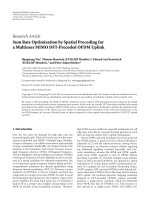
the subcarriers with the highest gain. For example, Figures
5(a) and 5(b) show snapshots of 30 VPs over a 128 subcarrier
solution space before and after convergence which is the
concatenation of two links (TD and TR) with 64 frequencies
in each link. The PSO algorithm will choose the subcarriers
with the highest gains.
In TS2, the subcarriers for the RD link are al located from
N frequencies. The allocation is performed by the relay node,
and N
RD
subcarriers with the highest channel gain in the RD
link are chosen using similar method to that just described.
However, the solution space will only contain the channel
gains profile of the RD link described as following:
S
=
h
RD
1
e
j∅
2
,
h
RD
2
e
j∅
2
, ,
h
RD
N
e
j∅
2
. (7)
The number of utilized subcarriers in TS2 is N
RD
= N
TR
,
because the same amount of data received in TS1 over
TR is t ransmitted to the destination using RD. Since the
transmitter and the relay nodes communicate over two
orthogonal time slots, having similar subcarriers used for the
RD and T R links will not cause any interference.
5.1.2. Cross-Layer Strategy. In the second resource allocation
strategy, a joint measure of channel gain and distance is
considered to eliminate the effect of path loss by choosing
more subcarriers from the links with a shorter distance.
When employing strategy 1, a larger number of subcarriers
are used for sending data of the transmitter compared to
noncooperative adaptive multicarrier systems. The system
can be further improved by considering the distance of the
transmitter relay and transmitter destination. It is assumed
that the relay node is physically located between the trans-
mitter and destination nodes. The channel information is
obtained from the physical layer whilst distance information
is gathered from the network layer. In strategy 2 the effect of
path loss is taken into account when selecting subcarriers.
Assuming isotropic antenna on each node, the path-loss
factor [18] for a signal is given by
C
=
4πd
λ
2
,(8)
EURASIP Journal on Wireless Communications and Networking 7
20 40 60 80 100 120
−3
−2
−1
−2.5
−1.5
−0.5
0
1
2
0.5
1.5
Sub-carriers
Sub-carriers gain (dB)
Channel profile
Distributed VPs over sub-carriers
(a)
20 40 60 80 100 120
−3
−2
2
−1
−2.5
−1.5
−0.5
0
1
0.5
1.5
Sub-carriers
Sub-carriers gain (dB)
Channel profile
Distributed VPs over sub-carriers
(b)
Figure 5: Snapshots of channel profile of TD and TR links and distributed VPs for a single user (a) before convergence and (b) after
convergence.
where d is the distance between transmitter and receiver
and λ is the wavelength of the signal. By normalizing the
wavelength to unity, the cost of transmission over direct link,
TD, and indirect link, TR, based on the path-loss is defined
by
C
D
=
(x
T
− x
D
)
2
+(y
T
− y
D
)
2
,
C
I
=
(x
T
− x
R
)
2
+(y
T
− y
R
)
2
,
(9)
where C
D
is the cost of using direct link and C
I
is the
cost of using the indirect link. Further, (x
T
,y
T
), (x
D
,y
D
)and
(x
R
,y
R
) are the coordinates of transmitter, destination, and
relay nodes, respectively. In TS1, the channel gain per cost
profile is considered as the solution space, S, and is formed
by concatenating channel g ains of TR and TD multiplied by
the inverse of the cost as following:
S
= (C
I
)
−1
h
TR
1
e
j∅
2
,
h
TR
2
e
j∅
2
, ,
h
TR
N
e
j∅
2
(C
D
)
−1
h
TD
1
e
j∅
2
,
h
TD
2
e
j∅
2
, ,
h
TD
N
e
j∅
2
.
(10)
The N subcarriers with the highest fitness function are
allocated from the TR and TD links. The fitness function
is equal to the nth subcarrier channel gain per cost value.
The centralized PSO algorithm, which runs at the transmitter
node, terminates when one of the termination criteria (1)
or (2) occurs. Figures 6(a) and 6(b) are the channel profiles
of the TR and TD links when N
= 128. As can be seen in
Figure 6(c) after combining the channel profiles of two links
and multiplying them by cost of each link, the fitness value
of each subcarrier will indicate a joint measure of cost and
channel gains. The subcarriers with lower cost stand higher
than those with high cost. Figure 6(c) shows 30 randomly
distributed VPs over the solution space before convergence.
Based on centralized PSO with VPs, the subcar riers w ith the
higher fitness values are selected. Figure 6(d) shows the VPs
after convergence over the subcarrier with the highest fitness
function. A threshold line is provided to demonstrate the
difference between the channel gain per cost of subcarriers
in direct and indirect links.
In TS2, a single link exists between relay and destination
node and the distance only affects the scale of the solution
space. Therefore, the subcarrier allocation is performed in a
similar way to TS2 in strategy 1.
5.2. Distributed PSO for Relay Node Selection. As the sub-
carriers in adaptive MCCC system are exclusively allocated
and the number of allocated subcarriers contributes to the
data rate of the nodes, it is important to choose a node
with low traffic for cooperation. Therefore, the node with
the lowest traffic overhead in the network is chosen as the
relaynode.Theselectionprocessisperformedonce,prior
to cooperation amongst nodes. Because of the distributed
nature of the particles, the proposed distributed PSO model
is suitable for efficient processing with different objectives.
The two-dimensional solution space, S
1
, S
2
,isdefinedas
following:
S
1
=
s
1
1
, s
1
2
, , s
1
X
,
S
2
=
s
2
1
, s
2
2
, , s
2
Y
,
(11)
where X and Y are the dimensions of the landscape. The
fitness function, f (S
1
, S
2
), is equal to the inverse of the load
ofanodeinlocationof(S
1
, S
2
).Theloadofanodeisa
measure of the tasks (i.e., packets) that need to be processed.
It is assumed that this load remains constant during the
optimization process. The processing load of a node in (x,y)
with U number of task queues, is given by
f
S
1
, S
2
=
1
U
u
=1
L
s
1
x
,s
2
y
,u
, (12)
where L
s
1
x
,s
2
y
,u
is the size of the uth task queue. The distance
is measured using (2) and the number of particles is l ess
8 EURASIP Journal on Wireless Communications and Networking
20 40 60 80 100 120
−1
−0.5
0
0.5
1
Sub-carrier number (TR link)
Channel gain (dB)
(a)
20 40 60 80 100 120
−1
−0.5
0
0.5
1
Channel gain (dB)
Sub-carrier number (TD link)
(b)
50 100 150 200 250
Channel gain per cost
−3
−2
−1
0
1
2
Sub-carrier number (composite TD and TR links)
Threshold line
Channel profile(fitness value)
Distributed VPs
(c)
Channel gain per cost
Channel profile(fitness value)
Distributed VPs
Threshold line
50 100 150 200 250
−3
−2
2
−1
0
1
Sub-carrier number (composite TD and TR links)
(d)
Figure 6: Snapshot of channel profile for N = 128 in the (a) TR link and (b) TD link and channel gain per cost profile (length of 2N) with
30 randomly distributed VPs (c) before convergence and (d) after convergence.
than the number of nodes. The movement of particles in an
ad hoc network introduces high traffic and computational
complexity. Additionally, it may take a long time to converge.
The traffic overhead is caused by the movement of particles
and their associated information such as history of PB. To
reduce the overheads, TPSO technique is proposed to adapt
particles behaviour by changing w
n
, w
s
,andP values which
affects social influence, nostalgia, and number of particles
in the algorithm. The training process could be p erformed
manually by observing the behaviour of the particles in a
specific system or using artificial intelligence techniques such
as neural networks [19].
At the beginning of the TPSO process, the particles are
randomly distributed among the nodes. In the network, the
packets move only through the single available route between
two neighbouring nodes. Since the solution space is equal
to the position of nodes, and is a sparse matrix, it is not
expected to find any solution between two neighbouring
nodes. Therefore, the movement of particles between two
neighbouring nodes that is caused by uncertainty between
nostalgia and social influence will not lead to finding a new
PB or GB value. By manual training, the particles are forced
to always follow the social influence (choosing the GB as the
next destination) using the following configuration: w
s
= 1,
w
n
= 0. This configuration will avoid redundant movements
of the particles between two neighbouring nodes, thus
reducing traffic and computational complexity.
Figure 7 shows the flowchart of the TPSO algorithm for
an ad hoc network. The particles are implemented on each
node using an identical software agent, called the particle
process (PP). It is responsible to calculate, compare and
update the PB and the GB values as well as moving the
particle towards GB. Updating of GB is achieved using a
broadcast algorithm in the network layer.
Since this updating is per formed occasionally, the
incurred overheads are neglected. The PP of a node runs
only when at least one particle is over that node. Therefore,
increasing the number of particles over a node will increase
the computational complexity overhead. Particles move
between two nodes by using a flag, carried by the data packets
circulating in the network. The flag indicates when to run a
PP process in a node and is also used for counting the PIDs
EURASIP Journal on Wireless Communications and Networking 9
C = count number
of PIDs on the
solution space
Start
C>0
C>1
Calculate the LB
using the fitness
function
Move the particle
to the GB
LB > GB
Generate a super
particle
Replace the GB
with the LB
Yes
YesYes
Yes
No
No
NoNo
C = total number
of particles
Announce end of
optimization
Broadcast the new
GB to all particles
in the system
End
Figure 7: Flowchart of the TPSO algorithm for ad hoc network.
over a node. Since particles move among the nodes using
data packets, their movement and direction depend on the
availability of connection between the nodes.
In TPSO, all particles on a node have similar destinations
which are either GB or the next hop towards GB. To further
reduce the traffic overhead and computational complexity on
a node, the particles are batched in a single super particle.
The super particle which is the aggregation of all the particles
on the node has a new PID that is known to the PP processes.
The super particle calculates fitness and chooses the next
direction in a similar method to normal particles. However,
in order to check for termination criteria (1), mentioned
in Section 3, the number of batched particles in a super
particle is considered for calculating the number of PIDs in
PP. For example, a node with 8 normal and a single super
particle consisting of 10 particles, would have a total of 18
PIDs. Using super particles will gradually reduce the number
of particles in running the system as the TPSO process
continues as result of batching them. The TPSO terminates
when one of the termination criteria, explained in Section 3,
is met.
Figure 8 shows a snapshot of the proposed TPSO algo-
rithm. The weights on each node represent the processing
load on that node and the distributed circles on the nodes
show the particles. As the process progresses, the particles
converge over the node with the highest load. Based on
the termination criteria explained before, the algorithm
broadcasts the found s olution to the other nodes when
all particles have converged over a node or the maximum
number of iterations has been reached.
6. Computation Complexity and Traffic Analysis
6.1. Computation Complexity. Computational complexity is
ameasureofhowefficiently the available resources are
utilized to perform the algorithm. One dimension of com-
putational complexity is the time that the algorithm takes
to terminate. Time complexity of an algorithm, regardless
of execution platform specifications, is measured in terms of
number of iterations using Big-O, O(
·), notation [20] which,
for the rest of paper, will be referred to as computational
complexity.
Centralized PSO. The centralized PSO algorithm does not
linearly search the solution space. Therefore, the possibility
of finding the optimum solution before exploiting all possi-
bilities is very high. Assuming that the order of an iterative
optimization for N elements on average consists of two
parts O()
× O( G( )), where the first part corresponds to the
number of iterations, and the second part is the complexity
of the logic of the optimization algorithm. In multicarrier
systems most of subcarrier allocation techniques use an
unsorted list of subcarriers [21]. These techniques have high
order of O(N)[20], for the required linear search to find
the highest gains for each user on each interval. The linear
search process gets even m ore complex when the user needs
an unknown number of subcarriers at each transmission. To
reduce the required number of iterations the authors of [22]
have used a sorted list of subcarriers. Using conventional
sort algorithms, maintaining a sorted list of subcarriers in
a time-variant channel introduces high order of O(N log N)
[20]. PSO-aided subcarrier allocation uses an unsorted list of
subcarriers to avoid the complexity overhead introduced by
sorting. However, searches of the list are much simpler and
faster than normal linear search algorithms. The complexity
order of the PSO process based on the provided algorithm
in Algorithm 1, using the principles of average case study
[20], is given by O(log N). Using the O(
·) function, Figure 9
shows the difference of linear search and sorted list selection
algorithms in comparison to the PSO-aided technique for
adifferent number of subcarriers. In addition, PSO is
flexible on its parameters such as number of VPs and the
employed fitness function, to enable controlling algorithm
performance.
10 EURASIP Journal on Wireless Communications and Networking
16
46
47
29
42
16
8
1
5
21
42
47
45
4
23
44
42
3
2
43
6
48
3
42
30
29
41
29
46
23
4
29
26
45
6
49
38
49
48
1
29
46
34
29
41
36
28
32
33
12
0 20406080100
0
10
20
30
40
50
60
70
80
90
100
X axis (m)
Y axis (m)
(a)
20 40 60 80 100
0
0
10
20
30
40
50
60
70
80
90
100
47
29
42
16
8
1
5
21
42
47
45
4
23
44
42
3
2
43
6
48
3
42
30
29
41
29
46
23
4
29
26
45
6
49
16
38
46
49
48
1
29
46
34
29
41
36
28
32
33
12
X axis (m)
Y axis (m)
(b)
Figure 8: Snap shot of TPSO in ad hoc network with 50 nodes and 30 particles showing particles (a) before convergence, (b) after
convergence.
0 50 100 150 200 250 300 350 400 450 500
10
4
10
3
10
2
10
1
10
0
Number of sub-carriers
Number of iterations
PSO-aided
Linear search
Sorted list
Figure 9: Complexity comparison of linear search, sorted list, and
PSO-aided subcarrier allocation algorithms.
It is shown by simulation that increasing the number
of VPs reduces the number of iterations needed to find
the optimum result. Figure 10 shows number of iterations
needed to find the GB value for a PSO-aided subcarrier
allocation for 128 subcarriers in a node. As can be seen
the number of iterations decreases as the number of VPs
increases due to faster convergence. Although employing
small number of VPs requires less memory, it may lead to
a suboptimal result as not all the solution space may be
explored.
Distributed PSO. In distributed scenarios the number of
particles on a node impacts the number of iterations in
5 1015202530354045505560
5
10
15
20
25
30
35
40
Number of VPs
Number of iteration
Figure 10: Iteration number for different number of VPs.
the algorithm. Computational complexity of the distributed
PSO on a single node is in order of O(g(Γ)) where g(Γ)
is the complexity function for Γ iterations on each node
and is defined according to algorithm implementation. The
complexity will increase to O(Qg(Γ)) when Q number of
particles (Q<P) overlap on the node. In TPSO, when there
is more than one particle over a node, they are collectively
considered as one super particle. Each super part icle is
treated in a similar way to normal particles, and hence using
super particles reduces the number of required packets. Since
Q and Γ are reduced as a result of batching the particles with
an identical destination to a super particle, the algorithm
will run fewer iterations and hence the overall computational
complexity will decrease.
EURASIP Journal on Wireless Communications and Networking 11
10 15 20 25 30 35 40
0
1000
2000
3000
4000
5000
6000
7000
8000
9000
10000
11000
Particle number
PSO traffic
TPSO traffic
Traffic(byte)
(a)
10 15 20 25 30 35 40
0
20
40
60
80
100
120
140
Particle number
Iteration
PSO
TPSO
(b)
Figure 11: (a) TPSO traffic overhead in relation to PSO based on Tabl e 2 and (b) convergence speed of particles (iterations) for TPSO and
PSO algorithms in the ad hoc network with 50 nodes for different number of particles.
Table 2: PSO and TPSO packet sizes and description used in the
simulation.
Packet type
Packet size in
TPSO
Packet size
in PSO
Description
GB Broadcast 2 2
For broadcasting the
value and location of
the GB.
P
Move 1 4
For moving the particle
from one node to
another node. For PSO
it contains PID, PB
location and value and
destination address.
For the TPSO it only
contains PID.
Terminate 1 1
A unique packet to
indicate optimization
termination
6.2. Traffic Analysis. In this section, trafficanalysisfor
distributed PSO and TPSO are provided for a relay node
selection process in an ad hoc network with 50 nodes.
Both techniques are simulated and the gain of training
the particles is demonstrated in relation to nontrained
algorithm. In Table 2 we introduce the packets used in
the simulated network. Assuming that each portion of
data occupies only one byte, the size of packets for each
packet type is calculated. In this experiment the overheads
caused by the routing protocol of the network layer are not
considered.
Figure 11(a) shows the average trafficoverheadcausedby
P
Move packets for PSO and TPSO in the aforementioned
(0, 1)
(0, 0)
TD
R
(1, 0)
Figure 12: Three ad hoc nodes (transmitter, relay, and destination)
using PSO-aided adaptive MCCC.
ad hoc network. The reduction in the trafficoverheadis
due to moving of less data between nodes. As a result of
training, all particles always move towards the node with
the GB value and do not return to their PB location. The
GB location may change during the optimization process.
However, at each interval all particles in the system move
towards the same destination, the current GB. Since each
super particle is treated in a similar way to normal particles,
using super particles in TPSO reduces the number of
required packets. In Figure 11(b) the average convergence
time for PSO and TPSO based on the simulation results for
different numbers of particles is demonstrated. The results
show that when using TPSO the particles converge over
the optimization solution with a near constant number of
iteration in relation to PSO, w here the achieved gain is due
to training of particles. It should be noted that training
the particles in this method is heavily dependent on the
scenario which the PSO is trained for and hence it is not
general.
12 EURASIP Journal on Wireless Communications and Networking
024681012141618
Bit error rate
Adaptive BPSK OFDM
BPSK OFDM
BPSK OFDM, dual diversity
10
0
10
−1
10
−2
10
−3
10
−4
E
b
/N
o
(dB)
Adaptive MCCC, TR-SNR
= 50 dB
Adaptive MCCC, TR-SNR
= 20 dB
Adaptive MCCC, TR-SNR
= 10 dB
Figure 13: Bit error rate performance of adaptive MCCC technique
using the first subcarrier allocation strategy for different TR-SNR.
7. Bit Error Rate Performance
In this section, the bit error rate performance of the
PSO-aided adaptive MCCC technique is investigated by
simulation. The bit error rate is a measure widely used
to demonstrate and compare the performance of digital
communication systems for a given signal to noise ratio
(SNR) or energy per bit per noise (E
b
/N
o
) where the
energy and noise are normalized to unity. In a binary
modulated system, SNR and E
b
/N
o
are identical [18]. It is
assumed that the relay node is selected by PSO in an ad
hoc network. The nodes transmit using equal power and
BPSK modulation over 128 subcarriers. The channel between
each two nodes is assumed to be uncorrelated multipath
fading with Rayleigh distribution where each subcarrier faces
flat fading. Figure 12 shows the cooperative communicating
nodes and their coordinates in the landscape. The results
for the proposed resource allocation strategies are compared
with single and dual receiver diversity BSPK OFDM using
128 subcarriers where all subcarriers, regardless of channel,
are utilized for transmission [15]. It has been shown that
the error rate performance of cooperative communications
with high SNR channel between the cooperating nodes
reaches the performance of dual receiver diversity [23].
Therefore, it is used as a bound for comparison purpose
in cooperative systems. Utilizing diversity enables processing
multireplica of a transmitted signal and hence significantly
improves performance [18]. The performance of adaptive
BPSK OFDM is also provided for comparison using the
introduced adaptive OFDM with 30 VPs where half of the
available subcarriers are adaptively allocated based on the
channel gains [4].
0 5 10 15 20 25 30
10
0
10
−1
10
−2
10
−3
10
−4
Bit error rate
E
b
/N
o
(dB)
BPSK OFDM, pathloss
= 15 dB
BPSK OFDM, pathloss
= 0dB
Adaptive MCCC—strategy 1
Adaptive MCCC—strategy 2
Figure 14: Bit error rate performance of adaptive MCCC technique
of the first and second subcarrier allocation strategies where path-
loss for TD and TR links is 15 dB and 20 dB, respectively.
Figure 13 shows the bit error rate performance of the
PSO-aided adaptive MCCC system when N/2 of the available
subcarriers using the first strategy. The results show that the
performance of adaptive BPSK OFDM and adaptive MCCC
are identical when the TR link has high SNR (i.e., 50 dB).
High SNR in TR link reduces the error rate at the relay link
and hence correctly received data bits are retransmitted by
the relay node. It is shown that the TR-SNR affects the error
rate performance at the destination. The bit error rate at the
designation node increases when the quality of the TR links
degrades (i.e., 10 and 20 dB). By choosing the relay node as
the nearest node to the tr ansmitter, the TR-SNR increases
and the bit error rate reduces at the destination. Since the
relay node does not repeat the data transmitted over the TD
link, no diversity gain is expected. However, the error rate
performance is improved in comparison to BPSK OFDM
because of adaptive allocation of subcarriers. It should be
noted, further performance improvements could be achieved
by transmitting identical data over TD and TR links to gain
from channel diversity.
In Figure 14, the bit error rate comparison between the
two PSO-aided subcarrier allocation st rategies is provided.
In this simulation, the transmitted signal power is attenuated
by the path loss over the TD and RD links. Having a
normalized Gaussian noise, the effective SNR at the receiver
is (E
b
/N
o
—path loss in dB). It is assumed that the path-
loss of the TD link is 15 dB, and the path loss of the RD
link is 20 dB. By calculating the effective SNR, the bit error
rates in this figure are comparable to the results with the
same E
b
/N
o
in Figure 13 (i.e., 20 dB in Figure 14 is equal to
5dBinFigure 13). In the second resource allocation strategy,
C
D
= 1andC
I
=
√
2, using (9) and (12) based on the
EURASIP Journal on Wireless Communications and Networking 13
coordinates given in Figure 12. As is shown in the figure,
the adaptive MCCC technique using the second strategy
has better performance in comparison to the first strategy.
The reason is that the TR link has 5 dB higher path loss in
comparison the TD link which is not considered in the first
strategy.
8. Conclusion
In this paper, a gener alized PSO model for adaptive resource
allocation in communication networks has been proposed
to reduce computational complexity in centralized and dis-
tributed resource allocation scenarios. The proposed model
consists of PSO with VPs for centralized and TPSO for
distributed optimizations which has been applied to resource
allocation in the adaptive MCCC technique. Centralized PSO
has been utilized for single layer and cross-layer subcarrier
allocation to reduce computational complexity. Distributed
TPSO has been utilized to reduce trafficoverheadinadaptive
relay node selection. The investigations show that the PSO
technique provides less complex approach than linear and
sorted list searches for subcarrier allocation which have
been used in the literature. The introduced techniques
are also flexible with regard to the number of particles
and the fitness function. It has been shown that TPSO
technique significantly reduces the trafficoverheadofthe
node selection process in comparison to PSO. Moreover,
the bit error rate performances for the single layer and
cross layer strategies are demonstrated for the PSO-aided
adaptive MCCC technique. Application of the proposed
generalized PSO model to other communication techniques
and scenarios are subject to further investigation.
References
[1] J. Kennedy and R. C. Eberhart, “Particle swarm optimization,”
in Proceedings of the IEEE International Conference on Neural
Networks IV, vol. 4, pp. 1942–1948, December 1995.
[2]A.S.Tanenbaum,Computer Networks, Prentice Hall, New
York, NY, USA, 4th edition, 2002.
[3] J. Robinson and Y. Rahmat-Samii, “Particle swarm optimiza-
tion in electromagnetics,” IEEE Transactions on Antennas and
Propagation, vol. 52, no. 2, pp. 397–407, 2004.
[4] S. Ghcitanchi, F. H. Ali, and E. Stipidis, “Particle swarm opti-
mization for resource allocation in OFDMA,” in Pro ceedings of
the 15th International Conference on Digital Signal Processing
(DSP ’07), pp. 383–386, Cardiff, Wales, July 2007.
[5] S. Gheitanchi, F. H. Ali, and E. Stipidis, “Trained particle
swarm optimization for collaborative computing networks,”
in Proceedings of the Convention Communication, Interaction
and Social Intelligence (AISB ’08), vol. 11, pp. 7–12, Aberdeen,
Scotland, 2008.
[6] J. Tillett, R. Rao, and F. Sahin, “Cluster-head identification in
ad hoc sensor networks using particle swarm optimization,” in
Proceedings of the IEEE Personal Wireless Communications,pp.
201–205, 2002.
[7] S. M. Guru, S. K. Halgamuge, and S. Fernando, “Particle
swarm optimisers for cluster formation in wireless sensor
networks,” in Proceedings of the Intelligent Sensors, Sensor
Networks and Informat ion Processing Conference, pp. 319–324,
December 2005.
[8] X. Wu, L. Shu, J. Yang, H. Xu, J. Cho, and S. Lee, “Swarm based
sensor deployment optimization in ad hoc sensor networks,”
in Proceedings of the International Conference on Embedded
Software and Systems (ICESS ’05), vol. 3820 of Lecture Notes
in Computer Science, pp. 533–541, 2005.
[9] P. Yuan, G X. Wang, and Y Y. Zhang, “Particle swarm opti-
mization approach of solving communication optimization
problems,” Journal of Northeastern University, vol. 25, no. 10,
pp. 934–937, 2004.
[10] S. Gheitanchi, F. H. Ali, and E. Stipidis, “Adaptive multi-carrier
cooperative communication technique,” in Proceedings of the
5th International Conference on Broadband Communications,
Networks, and Systems (BROADNETS ’08), pp. 372–376,
London, UK, September 2008.
[11] V. Srivastava and M. Motani, “Cross-layer design: a survey and
the road ahead,” IEEE Communications Magazine, vol. 43, no.
12, pp. 112–119, 2005.
[12] A. Goldsmith, Wireless Communications, Cambridge Univer-
sity Press, Cambridge, UK, 2005.
[13] A. Czylwik, “Adaptive OFDM for wideband radio channels,” in
Proceedings of the IEEE Global Telecommunications Conference,
vol. 1, pp. 713–718, London, UK, 1996.
[14] C H. Yih and E. Geraniotis, “Adaptive modulation, power
allocation and control for OFDM wireless networks,” in
Proceedings of the 11th IEEE International Symposium on
Personal, Indoor and Mobile Radio Communications (PIMRC
’00), vol. 2, pp. 809–813, September 2000.
[15] L. Hanzo, M. Munster, B. J. Choi, and T. Keller, OFDM
and MC-CDMA for Broadband Multi-User Communications,
WLANs and Broadcasting, John Wiley & Sons, New York, NY,
USA, 2003.
[16] B. Sklar, Digital communications Fundamentals and Applica-
tions, Prentice Hall, New York, NY, USA, 2001.
[17] Texas Instruments, 2009, www.TI.com.
[18] J. G. Proakis, Digital Communications, McGraw–Hill, New
York, NY, USA, 4th edition, 2001.
[19] S. Haykin, Neural Networks: A Comprehensive Foundation,
Pearson Education, Upper Saddle River, NJ, USA, 2nd edition,
1998.
[20]B.RaphaelandI.Smith,Fundamentals of Computer-Aided
Engineering, John Wiley & Sons, New York, NY, USA, 2003.
[21] H. Rohling, K. Brunighaus, and R. Grunheid, “Comparison
of multiple access schemes for an OFDM downlink system,”
in Multicarrier Spread Spectrum, pp. 23–30, Kluwer Academic,
Boston, Mass, USA, 1997.
[22] D. Kivanc, G. Li, and H. Liu, “Computationally efficient
bandwidth allocation and power control for OFDMA,” IEEE
Transactions on Wireless Communications,vol.2,no.6,pp.
1150–1158, 2003.
[23] J. N. Laneman, D. N. C. Tse, and G. W. Wornell, “An
efficient protocol for realizing cooperative diversity in wireless
networks,” in Proceedings of the IEEE International Symposium
on Information Theory (ISIT ’01), p. 294, June 2001.