Báo cáo hóa học: " Research Article VLSI Implementation of a Fixed-Complexity Soft-Output MIMO Detector for High-Speed Wireless" pptx
Bạn đang xem bản rút gọn của tài liệu. Xem và tải ngay bản đầy đủ của tài liệu tại đây (1.17 MB, 13 trang )
Hindawi Publishing Corporation
EURASIP Journal on Wireless Communications and Networking
Volume 2010, Article ID 893184, 13 pages
doi:10.1155/2010/893184
Research Article
VLSI Implementation of a Fixed-Complexity Soft-Output MIMO
Detector for High-Speed Wireless
Di Wu (EURASIP Member),
1, 2
Johan Eilert,
1, 2
Rizwan Asghar,
1
and Dake Liu
1
1
Department of Electrical Engineer ing, Link
¨
oping University, 58183 Link
¨
oping, Sweden
2
ST-Ericsson AT AB, Lund, Sweden
Correspondence should be addressed to Di Wu,
Received 30 September 2009; Revised 17 May 2010; Accepted 23 June 2010
Academic Editor: Tas¸kin Kocak
Copyright © 2010 Di Wu et al. This is an open access article distributed under the Creative Commons Attribution License, which
permits unrestricted use, distribution, and reproduction in any medium, provided the original work is properly cited.
This paper presents a low-complexity MIMO symbol detector with close-Maximum a posteriori performance for the emerging
multiantenna enhanced high-speed wireless communications. The VLSI implementation is based on a novel MIMO detection
algorithm called Modified Fixed-Complexity Soft-Output (MFCSO) detection, which achieves a good trade-off between
performance and implementation cost compared to the referenced prior art. By including a microcode-controlled channel
preprocessing unit and a pipelined detection unit, it is flexible enough to cover several different standards and transmission
schemes. The flexibility allows adaptive detection to minimize power consumption without degradation in throughput. The VLSI
implementation of the detector is presented to show that real-time MIMO symbol detection of 20 MHz bandwidth 3GPP LTE and
10 MHz WiMAX downlink physical channel is achievable at reasonable silicon cost.
1. Introduction
Multi-antenna or multi-in and multiout (MIMO) tech-
nologies have been widely adopted by the latest wireless
standards such as 3GPP LTE and WiMAX to enhance the
spectrum efficiency. For MIMO systems, a major challenge
is the symbol detection at the receiver. In particular, as
channel coding (e.g., Turbo) is used, soft output (the log-
likelihood ratio, LLR) must be computed as the input to
the channel decoder. Consider a MIMO system with n
TX
transmit antennas and n
RX
receive antennas. Let s be a
transmitted vector of length n
TX
, obtained by mapping a set
of information bits onto an M-QAM constellation L. Then
the received vector of length n
RX
is given by
r
= Hs + n
,(1)
where H is an n
RX
× n
TX
complex-valued channel matrix
which is assumed to be known. s is the transmitted symbol
vector. n is noise vector and r is the received symbol vector.
The optimum soft detector is Maximum-A-Posteriori (MAP)
detector which computes
L
(
b
i
| r
)
= log
⎛
⎝
s:b
i
(
s
)
=1
exp
−
1/σ
2
r − Hs
2
s:b
i
(
s
)
=0
exp
−
1/σ
2
r − Hs
2
⎞
⎠
. (2)
Here “s : b
i
(s) = β”meansalls for which the ith bit of s is
equal to β. Computing (2) requires enumeration of the entire
set of possible transmitted vectors. The complexity of doing
thisisusuallynotaffordable in practice.
As a trade-off between performance and complexity,
various MIMO detection methods such as sphere decoding
[1, 2], fixed complexity sphere decoding [3, 4], and MFCSO
decoding [5] have been proposed to reach near-MAP
performance with lower complexity than MAP. In [6], VLSI
implementation of a complexity reduced K-best detector for
2
×2 MIMO and 16-QAM is presented for WiMAX/WiFi. In
[7], VLSI implementation of a soft-output MIMO detector
for 2
× 2 MIMO in WLAN is presented. Without QR
decomposition unit being included, it consumes 135 kGate
with a reduced candidate list. In [8],aK-bestdetectorfor
2 EURASIP Journal on Wireless Communications and Networking
Sync
timing
frequency
Pilot
extraction
Channel
estimation
Cell search
PMI, CQI, IR
calculation
H-ARQ
ACK/NACK
RF
RF
A/D
A/D
DFE
FFT
FFT
MIMO
detector
De-interleaving
soft combine
Block concat
Rate-matcher
Tur bo d ec oder
CRC
Figure 1: Functional flow of a 3GPP LTE/WiMAX receiver.
Layer
mapping
Pre-
coding
S
12
S
11
S
21
S
22
S
12
S
11
S
21
S
22
Time
Time
(a) Spatial multiplexing (SM), n
TX
= 2.
Layer
mapping
Pre-
coding
S
4
S
3
S
2
S
1
S
3
S
1
S
4
S
2
Subcarriers
Subcarriers
S
4
S
3
S
2
S
1
S
∗
3
−S
∗
4
S
∗
1
−S
∗
2
(b) Space-frequency block coding (SFBC), n
TX
= 2.
Figure 2: Downlink multi-antenna transmission schemes.
4×4 MIMO is implemented in a Xilinx Virtex-5 FPGA. How-
ever, the complexity of sphere decoding grows exponentially
with the number of transmit antennas and polynomially
in the size of the signal constellation. More importantly,
the tree search used in sphere decoding is in principle a
sequential procedure which is difficult to parallelize. In [3],
a fixed-throughput sphere detector is proposed with fixed
complexity and parallelism for hard decision. In [5],alow-
complexity near-MAP detection method is proposed for
high-order modulation (e.g., 64-QAM). The performance
loss from MAP due to the suboptimal search introduced
in MFCSO is proven by simulation to be small in [5].
However, in [5], the complexity of MFCSO is only presented
in number of arithmetic operations without the silicon cost
and processing latency being addressed and no comparison
with prior art is made. Most importantly, none of these
methods proposed have taken the system specific features of
LTE (e.g., OFDMA and H-ARQ) into consideration and are
mostly based on very simple channel models (e.g., AWGN).
In [9], limited evaluation of MFCSO is carried out with a
focus on LTE system.
In this paper, with the aid of more realistic LTE and
WiMAX simulation chains and different channel models,
several MIMO detection algorithms are applied to LTE and
WiMAX systems and with their performance quantitatively
evaluated. Second, although the MFCSO detection algorithm
proposed by the authors in [5]hasaverylowdetectioncom-
plexity, under random AWGN channels, it requires relatively
strong channel coding to maintain a near-MAP performance
in frame error ratio [5]. In this paper, its performance with
the aid of H-ARQ is investigated. In order to validate MFCSO
from VLSI implementation perspectives, both FPGA and
ASIC implementation of an MFCSO detector is presented.
Note that most commercial terminals are limited by cost and
power consumption, especially the power consumption of
the analog part of each antenna chain. According to the LTE
and WiMAX standards, 4
× 2and2× 2 MIMO schemes
are included as a good trade-off between performance gain
and complexity (or power consumption). Hence, only these
schemes are considered in here. The result is compared with
a state-of-the-art soft-output sphere decoding (SSD) [1]and
the K-best detector presented in [10]frombothperformance
and cost aspects.
The remainder of the paper is organized as follows. In
Section 2, the application of MIMO techniques in LTE and
WiMAX is presented. Section 3 introduces the linear and
MFCSO MIMO detection algorithms. Section 4 addresses
the detection flow. The architecture of the detector is
addressed in Section 5. The link-level simulation results
are presented in Section 6. Section 7 analyzes the imple-
mentation complexity, and Section 8 presents the adap-
tive method used to optimize power efficiency. Section 9
presents both the FPGA-and ASIC-based implementa-
tion of the detector. Finally, Section 10 concludes the
paper.
2. MultiAntenna in LTE and WiMAX
Wireless standards such as 3GPP LTE and WiMAX have
incorporated MIMO transmission schemes to boost the
peak data rate. Meanwhile, software-defined radio (SDR)
technologies allow both of them to be supported by the same
piece of hardware.
3GPP Long-Term Evolution (LTE) is the next generation
radio access technology which incorporates Orthogonal
EURASIP Journal on Wireless Communications and Networking 3
Channel
preprocessing
MMSE: W
= (H
H
H + σ
2
I)
−1
H
H
MFCSO: QR decomposition H
1
, H
2
LLR demapping
Channel
decoder
H
σ
y
W
L(b
i
k
)
b
i
k
Figure 3: Task flow of soft-output MIMO detection.
Frequency Division Multiple Access (OFDMA) as the mul-
tiple access scheme in downlink. MIMO technologies are
also mandatory in LTE to achieve the LTE bit-rate targets
(e.g 100 Mbit/s peak data rate for downlink). As part of the
receiver chain depicted in Figure 1,MIMOsymboldetection
is a significant challenge for VLSI implementation.
The input to the MIMO detector presented in this paper
includes the estimated channel matrix
H
=
h
11
h
12
h
21
h
22
,(3)
the received symbol vector r, and the estimated noise
variance σ
2
. The output of the detector is the LLR values of
the demodulated bits.
In both LTE and WiMAX, spatial multiplexing (SM)
and transmit diversity have been adopted as the two major
MIMO schemes. SM is a MIMO technique aimed at
maximizing the data throughput by exploiting the degrees
of freedom in MIMO channels. Since the multiplexing gain
is only available for high SNR region, spatial multiplexing
is usually used when high SNR is available. STBC/SFBC
[11] assumes the channel is stationary among adjacent time
intervals or subcarriers so that a single codeword is mapped
to these adjacent intervals or subcarriers to benefit from
either time or frequency diversity in transmission. The most
widely used STBC/SFBC scheme is Alamouti scheme in space
or frequency domain. Since STBC/SFBC only requires a
linear detector to achieve diversity, the detector design is
easier. Note that in this paper, only open-loop MIMO is
considered without feedback from the terminal.
2.1. Spatial Multiplexing. Spatial multiplexing is a MIMO
technique aimed at maximizing the data throughput by
exploiting the degrees of freedom in MIMO channels. Since
the multiplexing gain is only available in high SNR region,
spatial multiplexing is usually used when high SNR is
available. As depicted in Figure 2(a), spatial multiplexing
usually requires both n
RX
and n
TX
to be large. In general,
the degree of freedom (multiplexing gain) is determined
by min(n
TX
, n
RX
) which is the rank of the channel matrix
H.IncaseH is badly conditioned (e.g. when line-of-sight
occurs, H becomes a singular matrix), the pseudoinversion
of H in (15) using linear detection will be very difficult
which requires very large dynamic range. In other words,
the gain of spatial multiplexing heavily depends on the
multipath fading. A dual-stream spatial multiplexing scheme
is depicted in Figure 2 (a).
2.2. Transmit Diversity. Transmit diversity schemes that
exploit the diversity gain of multi-antenna transmission
have also been adopted by LTE and WiMAX. The Space-
Time Block Coding (STBC) in WiMAX and Space-Frequency
Block Coding (SFBC) in LTE [11] are both transmit diversity
schemes to transmit data for guaranteed diversity while
requiring only a low-complexity symbol detector on the
receiver side. In both cases, the Alamouti matrix [12]
is used because it is the only full-rate linear STBC (or
SFBC) code with a diversity gain of 2. In other words,
the transmit diversity schemes considered in this paper are
Alamouti schemes in the space and frequency domains. This
assumes the channels of either adjacent symbol intervals or
subcarriers are identical, so that either time or frequency
diversity will be achieved when a single codeword is mapped
to different antennas within two adjacent time or frequency
intervals. The basic 4
× 2 space-frequency channel matrix is
defined as
H
=
⎡
⎢
⎢
⎢
⎢
⎣
h
11
−h
12
h
12
−h
22
h
∗
12
h
∗
11
h
∗
22
h
∗
12
⎤
⎥
⎥
⎥
⎥
⎦
. (4)
3. Soft-Output MIMO Detection
The optimum soft-output MIMO detector computes the
Log-Likelihood Ratio (LLR) in (2). Commonly the sums
in (2) are approximated by their largest terms (“log-
max”) which requires the solution of problems of the type
min
r − Hs
2
,subjecttos ∈ L. Since MAP provides
the best theoretical performance, it is commonly used as a
benchmark when comparing other algorithms
L
(
b
i
| r
)
≈ log
⎛
⎜
⎜
⎝
s
1
∈L
···
s
r
∈L
max
s
r+1
, ,s
n
TX
exp
−
1/σ
2
r − h
1
s
1
−···−h
r
s
r
−H
s
r+1
, , s
n
TX
T
2
s
1
∈L
···
s
r
∈L
max
s
r+1
, ,s
n
TX
exp
−
1/σ
2
r − h
1
s
1
−···−h
r
s
r
−H
s
r+1
, , s
n
TX
T
2
⎞
⎟
⎟
⎠
. (5)
4 EURASIP Journal on Wireless Communications and Networking
Channel
preprocessing unit
Control
interface
H
y
PE
PE
L(b
i
k
)
Coefficient
memory
QR
W
Program
memory
Detection
unit
.
.
.
Figure 4: Block diagram of the dual-mode MIMO detector.
3.1. Linear De tection. In linear detection such as Zero-
forcing (ZF) and Minimum Mean Squared Error (MMSE),
the receiver symbol vector r is multiplied with a linear filter:
ZF :
s =
H
H
H
−1
H
H
r = s + n
ZF
,(6)
MMSE :
s =
H
H
H + σ
2
I
−1
H
H
r = s + n
MMSE
.
(7)
The correlation between the elements in the noise vector
n
is neglected and the symbols in s are demodulate
individually, treating the output of the model (6)asn
TX
independent scalar channels. Although linear detectors will
incur a severe performance loss in slow fading channels
[4], they have very low implementation cost compared to
more advanced MIMO detection algorithms which makes
them suitable for low-cost real-time implementations. As
depicted in Figure 3, the linear detection procedure involves
two parts: channel preprocessing and symbol demapping.
The channel preprocessing procedure mainly consists of
matrix multiplication and inversion as shown in (6)and
(7).
3.2. Fixed-Complexity Soft Output (FCSO). The Layered
Orthogonal Lattice Detector (LORD) proposed in [13]and
the FCSO MIMO detector presented in [4] are similar and
use a suboptimal method to reduce the complexity at the cost
of negligible performance loss. A general n
TX
× n
RX
MIMO
system using 64-QAM is taken as a case study. Here each
complex-valued symbol is considered to be one layer and
only the top layer is exactly marginalized with the remaining
three layers approximately marginalized. The channel-rate
processing of FCSO involves the QRD of n
TX
rank-reduced
channel matrices
H
k
=
h
1
, , h
k−1
, h
k+1
, , h
n
TX
,
(8)
which generates an upper triangular matrix R
k
, and a unitary
matrix Q
k
so that
H
k
= Q
k
R
k
. (9)
Here n
TX
QRD is needed for different H
k
.
μCcontrol
RF
CMAC CMAC
1/x
Figure 5: Channel preprocessing unit.
The symbol-rate processing consists of the following
steps.
(1) Pick one transmitted symbol s
i
, i ∈ (1, , n
TX
)as
the top layer. The entire constellation L is enumerated in
the exact marginalization (
in (5)) only for s
i
. For the kth
candidate
s
k
i
in L, by canceling its effect on the received
symbol vector r,anewvector
r = r −
h
i
s
k
i
(10)
is computed.
(2) By multiplying
r with Q
H
k
from (9), compute
r = Q
H
k
r
. (11)
(3)Basedon
r and R, using DFE, s
b
= [s
2
s
3
···s
n
TX
]
T
can be estimated using hard decision. From this, compute
the Euclidean distance
δ
k
=
r −R
k
s
b
2
(12)
and eventually the log-likelihood ratio (LLR). Taking a 64-
QAM system as an example, as shown in the following:
μ
(
b
1
, , b
24
)
= exp
−
1
σ
2
δ
k
(13)
the LLR of the six bits that constitute the top-layer symbol
can be computed using (12). This involves the computation
of 64 different δ
k
,(k = 1, , 64) as shown in (14)
EURASIP Journal on Wireless Communications and Networking 5
From
coefficient
memory
From
data
memory
Control
FSM
y
Preproc. CMAC
∗
+
EST. coord.
Candidate
index LUT
Ta ble o f
candidates
Coord.
Bits
y
R
Distance
Bits
Euclidean
distance calc
LLR update
Soft bits
Figure 6: PE in detection unit.
L
(
b
i
r
)
≈ log
⎛
⎝
1
b(
s
1
)
1
=0
···
1
b(
s
1
)
i−1
=0
1
b(
s
1
)
i+1
=0
···
1
b(
s
1
)
6
=0
max
b(s
2
)
1
,···,b(s
4
)
6
μ
(
b
1
, ···, b
i−1
,1,b
i+1
, , b
24
)
1
b(s
1
)
1
=0
···
1
b(s
1
)
i−1
=0
1
b(s
1
)
i+1
=0
···
1
b(s
1
)
6
=0
max
b(s
2
)
1
,···,b(s
4
)
6
μ
(
b
1
, ···, b
i−1
,0,b
i+1
, , b
24
)
⎞
⎠
. (14)
3.3. Modified FCSO (MFCSO). Although the FCSO detector
has substantially reduced the complexity compared to MAP
detector, further reduction is still needed for a practical
implementation with large signal constellations. In the
following, further approximations and improvements to
FCSO detection, namely Modified FCSO (MFCSO) detector
[5], are elaborated. In [4], the entire constellation L is
enumerated in the exact marginalization (
in (5)). In
this paper, instead of searching the full constellation L,
we propose to sum over only a subset L
s
⊂ L of
constellation points around an initial estimate
s. This initial
estimate will be obtained by zero-forcing detection. The size
of L
s
,denotedbyN, is chosen to be 16 and 8 in this
paper for the complexity and performance comparisons. In
effect, the proposed detector is a further approximation of
that in [4], which consists of only partially enumerating
the symbols selected for exact marginalization (the set
L in (5)).
Similar to FCSO, the channel-rate processing of MFCSO
involves computing QRD n
TX
times, as shown in (9)and(8).
As an overhead compared to FCSO, the coefficient matrix
W
=
H
H
H + σ
2
I
−1
H
H
(15)
is needed to perform the ZF/MMSE-based initial estimate of
s in (16) below. The symbol-rate processing of MFCSO is the
following
(1) Linear detection (ZF/MMSE) is carried out to
estimate the initial symbol vector
s = min
s
k
∈L
Hs − r
2
. (16)
Here s is the transmitted symbol vector, s
k
is the kth symbol
in it.
(2) For each initially estimated symbol
s
k
, k ∈
{
1, , n
TX
}, a candidate set L
k
is created. L
k
contains N
lattice points close to
s
k
.
(3) For each point l
∈ L
k
, approximate marginalization
is applied to the rest of the layers either via ZF or ZF-DFE.
According to (17), a multiplication of Q
H
k
and r is needed for
each
r which is updated proportionally to the size of L
k
and
the symbol rate. However, note that
r = Q
H
k
r = Q
H
k
(
r
−h
k
l
)
= Q
H
k
r −
Q
H
k
h
k
l, (17)
where Q
H
k
h
k
is an n
TX
×1 vector, which can be precalculated
at channel rate.
6 EURASIP Journal on Wireless Communications and Networking
343230282624222018
SNR
MMSE
MMSE (1st retr)
MFCSO
MFCSO (1st retr)
FCSO
FCSO (1st retr)
MAP
MAP (1st retr)
10
−4
10
−3
10
−2
10
−1
10
0
BLER
LT E B L E R
Figure 7: Block error ratio (2 ×2SM,CQI=15), red curves are the
BLER of the 1st retransmission of H-ARQ.
(4) Using back substitution [14], s
b
can be estimated
from
s
b
= arg min
s
k
∈L
R
k
s
b
− r
2
.
(18)
(5)
s
b
together with s
k
form a complete possible transmit-
ted symbol vector which has an Euclidean distance
δ
l
=
R
k
s
b
− r
2
.
(19)
(6) In total, there will be N different l ∈ L values for each
layer, and there will be four layers each being the top layer
once. Therefore, for a 4
×4system,4N different δ
l
values need
to be computed. In case N
= 16, there will be 64 different δ
l
values which is 1/4 compared to the FCSO proposed in [4].
(7) For the sake of low complexity, instead of MAP
detection, the following approximation can be used, so that
L
(
b
i
(
s
k
))
≈−
1
σ
2
min
l∈L
k
:b
i
(s
k
)=0
δ
l
− min
l∈L
k
:b
i
(s
k
)=1
δ
l
. (20)
As presented in [5], the performance gap between MAP
and MFCSO for 4
× 4 MIMO using 64-QAM and 3/4
convolutional coding was proven to be small when N
= 16
(0.5 dB when FER
=10
−2
). The gap increases to 2 dB when
N
= 8. On the other hand, the complexity of the detector
when N
= 16 is already feasible for VLSI implementation.
3.4. MFCSO in LTE and WiMAX. As a simplification of
the general MFCSO algorithm presented in Section 3.3,
a2
× 2 MFCSO method for SM is elaborated in the
following. Considering each complex-valued symbol as one
layer, only one of them is exactly marginalized and the other
is approximately marginalized (using DFE hard decision).
The channel rate processing of MFCSO involves the QR
decomposition (QRD) of two 2
× 2 channel matrices which
are H
1
= H in (3)and
H
2
=
h
12
h
11
h
22
h
21
. (21)
The QRD generates an upper triangular matrix R,anda
unitary matrix Q according to (9).
The detection procedure for 2
× 2 SM described in the
following text is slightly different from the MFCSO presented
in [5].
(1) Linear detection in (16) is carried out to estimate the
2
×1 initial symbol vector
s
init
= min
s
init,k
∈L
H
1
s − r
2
.
(22)
Here s is the transmitted symbol vector, within which, s
k
is
the kth symbol.
(2) For each initially estimated symbol
s
init,k
, k ∈{1, 2},
a candidate set L
k
is created. L
k
contains N constellation
points close to
s
init,k
.
(3)Firsts
2
is chosen as the top-layer symbol. In order to
perform DFE,
r = Q
H
1
.
(23)
needs to be computed. The same operation is needed
once again when s
1
is chosen as the top layer later.
(4)For the n
th
constellation point ζ
n
∈ L
2
, its effect on r
1
will have to be canceled out.
r
1
= r
1
−R
1
(
1, 2
)
ζ
n
(24)
Based on ζ
n
, the partial Euclidean distance
δ
n
=
R
1
(2, 2)ζ
n
− r
2
2
(25)
computed for the top-layer.
(5) DFE is applied to detect the other layer. Using back
substitution [14],
s
1
can be estimated from
s
1
= arg min
s
1
∈L
R
1
(1, 1)s
1
− r
1
2
.
(26)
(6) The estimated
s
1
together with s
2
= ζ
n
form a
complete possible transmitted symbol vector
s,fromwhich
an accumulated full Euclidean distance
δ
n
= δ
n
+
R
1
(1, 1)s
1
− r
1
2
(27)
can be computed.
(7) In total, there will be N different δ
n
computed when
s
2
is chosen as the top layer. Then s
1
is chosen as the top-
layer symbol as well. Based on Q
2
, R
2
,ands
init,1
, the same
procedure needs to be done once again to compute another
N different δ
n
.Hence,forthe2× 2system,2N different δ
n
values need to be computed. They are used to update the LLR
values in the end as described in [5].
EURASIP Journal on Wireless Communications and Networking 7
Table 1: Operations supported by ChPU.
Operation Description
Cplx squared abs c = a.r
2
+ a.i
2
Sum squared abs c = a.r
2
+ a.i
2
+ b.r
2
+ b.i
2
Cplx inner product c =
(a
i
.r
2
+ a
i
.i
2
)
Cplx multiply c.r
= a.r ∗b.r − a.i ∗ b.i
c.i
= a.r ∗b.i + a.i ∗b.r
Cplx multiply-add c.r
= c.r + a.r ∗ b.r −a.i ∗ b.i
c.i
= c.i + a.r ∗b.i + a.i ∗b.r
Real-Cplx multiply c.r
= a.r ∗b; c.i = a.i ∗ b
Real Inverse-Sqrt b
= 1/
√
a
4. Flow Analysis of MIMO Detection
Independent of the detection method, the processing flow
of MIMO symbol detection can always be partitioned into
two parts, namely channel-rate processing and symbol-rate
processing as depicted in Figure 3.
4.1. Channel-Rate Preprocessing. The channel preprocess-
ing is about the precalculation of equalization coefficient
matrices from the estimated channel matrix H. According
to (15)), the computation involved in linear detection is
mainly matrix manipulation including matrix multiplication
and inversion. Here the matrix H can be a complex-
valued matrix of arbitrary size. As mentioned in [15], in
practice, the size of H is typically between 2
× 2and4× 4.
Although larger matrices (e.g., 8
× 8) can still be managed
[15], the cost of real-time implementation will be much
higher. For MFCSO, channel-rate processing includes the QR
decomposition in (9). For MFCSO, aside from computing W,
QR decomposition is also needed according to (9).
4.2. Symbol-Rate Processing. The symbol-rate processing in
soft-output linear detection [16] is to demap the equalized
complex values to soft bits. In case of near-MAP detection
methods such as MFCSO, layered processing is involved
which requires substantially more computational effort.
As described in Section 3.3, the symbol-rate processing in
MFCSO involves the multiplication, subtraction, and com-
puting the Euclidean distance based on estimated symbols.
5. Architecture of the MIMO Detector
The block diagram of the MFCSO detector is depicted in
Figure 4. The detector contains two major parts, the channel
preprocessing unit (ChPU) and the detection unit (DU).
As presented in Section 3.3 and [5], it is decided that the
candidate set size N
= 16 for 64-QAM. It allows real-time
detection of both 2
× 2 STBC/SFBC and SM for LTE and
WiMAX. Modulation schemes from QPSK to 64-QAM are
supported.
5.1. Channel Preprocessing Unit. The ChPU as depicted
in Figure 5 handles channel-rate processing tasks such as
computation of W in (15) and the QR decomposition in
(9). These are performed every time the estimated channel
is updated. The computed coefficient matrices W will be
stored in the coefficient buffer and fed to the LLR demapper
as input. As depicted in Figure 5, ChPU contains two
Complex-valued Multiply-and-ACcumulate (CMAC), an
inverse-square-root unit and a 32-bit register file containing
24 registers. The ChPU is a programmable unit controlled by
microcode. The operations supported by the ChPU are listed
in Ta bl e 1. The method presented in [16]hasbeenusedto
compute W, and the Modified Gram-Schmidt method [14]
is used to compute Q and R matrices in (9).
5.2. Detection Unit. TheDUcomputestheLLRvalues
using the method presented in Section 3 and the Log-Max
approximation in (20)
L
b
i
k
=−
1
σ
2
min
l∈L
k
:b
i
k
=0
δ − min
l∈L
k
:b
i
k
=1
δ
. (28)
The DU consists of a number of processing elements (PE)
as illustrated in Figure 6 which can utilize the parallelism in
the MFCSO algorithm. The computed LLR values L(b
i
k
)can
be either directly passed to the channel decoder or combined
with previously stored LLR values in the soft-buffer for H-
ARQ. Since the processing in DU is at symbol rate which
is much higher than the channel-rate processing in ChPU,
a fully pipelined architecture is used in DU to allow the
computation of 16 different δ
n
in (27) to be finished within
16 clock cycles. DU is configured by a control register and
can bypass the functions defined in Section 3 to only enable
MMSE detection with soft output. The MMSE mode can be
used in power saving mode to reduce the power consumption
with a loss of detection performance. A 16-bit fixed-point
datatype with proper scaling is adopted in DU, the output
LLR values are quantized to be 6-bit signed integers. The
number of PE in the DU is decided at design time according
to the processing load and latency analysis. In this paper,
it is chosen to be two based on the latency analysis in
Section 9.3.
5.3. Memory Subsystem. The MIMO detector itself does not
contain memory except the small program memory. In order
to store the temporarily computed W, Q
1
, R
1
, Q
2
,and
R
2
which are updated by the channel preprocessor at the
channel rate, a coefficient buffer as depicted in Figure 4 is
needed. The coefficient memory stores the above values for
all data subcarriers (up to 20 MHz bandwidth for LTE and 10
MHz to WiMAX). The FIFO that stores the incoming data to
the detector from the channel estimator and the subcarrier
demapper is not shown in the figure, neither is the FIFO
that passes the computed LLR values to the channel decoder
hardware. Note that in case STBC is used, the number of data
stored in W memory can be reduced almost by half owing to
the Alamouti features of W, and no Q and R matrices are
needed.
8 EURASIP Journal on Wireless Communications and Networking
343230282624222018
SNR (dB)
MMSE
K-best (K
= 16)
MFCSO
MAP
10
−4
10
−3
10
−2
10
−1
10
0
FER
Figure 8: LTE coded frame Error rate (rate 0.926, 64-QAM).
343230282624222018
SNR (dB)
MAP
MFCSO
K-best (K
= 16)
MMSE
10
15
20
25
30
35
40
Throughput (Mbit/s)
2.5 Mbit/s
5Mbit/s
7.6 Mbit/s
Figure 9: LTE coded throughput (rate 0.926, 64-QAM).
6. Performance Evaluation
In order to evaluate the performance of various MIMO
detection algorithms, simulation is carried out using link-
level 3GPP LTE and WiMAX simulators [17, 18]. The
simulators are developed using MATLAB and C.
It includes the complete physical layer signal processing
such as timing/frequency synchronization, channel esti-
mation, subcarrier demapping, rate-matching, and turbo
decoding. H-ARQ based on CRC of coded blocks is also
enabled to support chase combine (CC) with up to three
retransmissions. The bandwidth is set to be 5MHz in the
simulation, the velocity of UE is 3 km/h and the scenario
is urban micro [19]. Perfect synchronization and channel
estimation are assumed to focus the simulation on detection
302520151050−5
SNR (dB)
Coded (CQI
= 9)
Uncoded (CQI
= 9)
Coded (CQI
= 15)
Uncoded (CQI
= 15)
0
5
10
15
20
25
Throughput (Mbit/s)
Figure 10: Throughput (2 ×2 SFBC, MMSE).
302520151050−5
SNR
CQI
= 9
CQI
= 9(1stretr)
CQI
= 15
CQI
= 15 (1st retr)
10
−4
10
−3
10
−2
10
−1
10
0
BLER
LT E B L E R
Figure 11: Block error ratio (2 ×2 SFBC, MMSE).
performance. The Turbo decoder runs at most six iterations
with early stopping. The WiMAX simulator [17] also works
on 5MHz bandwidth. Two channel coding methods used
in the simulation are Reed-Solomon with Convolutional
(RS-Conv) and Low-Density Parity-Check (LDPC) coding.
Two channel models namely the 3GPP SCME [19]andITU
Pedestrian B (PedB) [17] channel models are used in this
paper. It is assumed the channel is quasistatic within one
OFDM symbol duration. Note that the 1-TTI latency is
introduced for uplink ACK/NACK in the simulation.
6.1. 3GPP LTE. Figure 7 shows the block error rate (BLER)
of the LTE system with H-ARQ using different detection
EURASIP Journal on Wireless Communications and Networking 9
35302520151050−5
SNR (dB)
Coded throughput (2
× 2 SM MFCSO)
Coded throughput (2
× 2 SM MMSE)
Coded throughput (2
× 2 SFBC MMSE)
0
5
10
15
20
25
30
35
40
Throughput (Mbit/s)
Figure 12: Coded throughput with 2-level AMC (CQI 15 and 9).
353025201510
SNR (dB)
MMSE (RS-Conv)
MFCSO (RS-Conv)
MAP (RS-Conv)
MMSE (LDPC)
MFCSO (LDPC)
MAP (LDPC)
10
−3
10
−2
10
−1
10
0
FER
Figure 13: WiMAX coded frame error rate (rate 0.75, 64-QAM).
methods. The blue curves are the BLER of the first
transmission while the red ones represent that of the first
retransmission in H-ARQ. The figure shows that the BLER
of the retransmission is drastically reduced compared to the
first transmission which improves the throughput as shown
later.
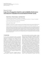
The result in Figures 8 and 9 shows that in case of 64-
QAM and the weakest (rate 0.926) channel coding defined
in LTE is used, for 2
× 2 SM, the FER performance of MAP
is always better than that of MFCSO and K-best. MFCSO
achieves lower FER than the K-best (K
= 16) used in [10]
until very high SNR. MMSE has the worst FER performance.
353025201510
SNR (dB)
MAP (LDPC)
MFCSO (LDPC)
MMSE (LDPC)
MAP (RS-Conv)
MFCSO (RS-Conv)
MMSE (RS-Conv)
0
5
10
15
20
25
30
Throughput (Mbit/s)
Figure 14: WiMAX coded throughput (rate 0.75, 64-QAM).
3432302826242220
SNR (dB)
MFCSO Det, LS channel Est
SSD Det, LS channel Est
MAP Det, LS channel Est
MFCSO Det, Perf channel Est
SSD Det, Perf channel Est
MAP Det, Perf channel Est
10
−3
10
−2
10
−1
10
0
BLER
BLER, 5 MHz, open-loop MIMO, PedB, 5000 subframes
Figure 15: LTE bLock error rate with H-ARQ (CQI=14), PedB.
Note that in wireless systems, throughput is a more impor-
tant performance factor than BER or FER because it has
a direct effect on the user experience. Figure 9 shows that
the gain in throughput brought by MFCSO against MMSE
is significant (up to 12.6 Mbits/s, or 55% higher than the
one achieved by MMSE). In comparison, the throughput
performance degradation caused by the approximation in
MFCSO is much smaller (up to 2.5 Mbits/s, or 7% lower
than that achieved by MAP). The much smaller gap in
10 EURASIP Journal on Wireless Communications and Networking
3432302826242220
SNR (dB)
MFCSO Det, LS channel Est
SSD Det, LS channel Est
MAP Det, LS channel Est
MFCSO Det, Perf channel Est
SSD Det, Perf channel Est
MAP Det, Perf channel Est
15
20
25
30
35
40
Throughput (Mbps)
Throughput, 5 MHz, open-loop
MIMO, PedB, 5000 subframes
Figure 16: LTE throughput with H-ARQ (CQI=14), PedB.
Table 2: Minimum SNR to reach FER
=0.01.
CQI SFBC (MMSE) SM (MFCSO) SM (MMSE)
9 10dB 17dB 24dB
15 24 dB 36 dB N/A
throughput in comparison to that of FER mainly owes to
the H-ARQ retransmission with chase combining. The result
shows that even with a sub optimal detector (with much
lower complexity than the optimal detector) and almost
no channel coding, a throughput that is close to the one
achievable by MAP detectors can still be reached when H-
ARQ is used. The throughput gain of MFCSO over the K-best
is as significant as 5 Mbits/s (14%), when SNR is 26 dB.
Figures 10 and 11 show the BLER and throughput of
2
× 2 SFBC with two different CQI values (9 and 15).
The simulation shows that SFBC reaches FER
= 0.01 at
much lower SNR than SM as depicted in Ta bl e 2, though the
throughput is half.
Figure 12 depicts the achievable throughput using two-
level adaptive modulation and coding (AMC). The result
shows that when SNR is worse than 10 dB, SFBC achieves
both higher throughput and lower BLER than SM even if
MAP detector is used.
6.2. WiMAX. The result in Figures 13 and 14 shows that
when mild channel coding (e.g., RS-Conv 3/4) is used
without H-ARQ in the WiMAX system, MFCSO still achieves
near-MAP performance in FER and MAP performance in
throughput. It has a gain of more than 9 dB compared
to the MMSE detector. The use of stronger code (e.g.
LDPC) will bring a gain of 4 dB in throughput compared
to RS-Conv. This shows that MFCSO has a very promising
performance/complexity trade-off taking the advance of
channel coding into consideration. The result also shows that
once FER reaches 0.01, any further improvement of FER
gives only negligible increase in throughput.
6.3. Impact of Channel Estimation Error. In most of the
literatures [1, 3, 5], perfect channel state information (CSI)
is assumed which is never true in reality. In [4], channel
estimation error is emulated with a randomly generated
error constrained by the value of its average power, and the
affected FER is plotted. However, how the channel estimation
error affects the link-level performance of MIMO detection
with the presence of H-ARQ has not been studied according
to the best knowledge of the authors. In this paper, based
on the least square (LS) channel estimation, the impact
of channel estimation error on link-level performance is
investigated, which provides a realistic measurement of the
achievable performance of the MFCSO detector in a practical
system. In this paper, an LTE system with CQI
= 14
(coding rate 0.8547, 64-QAM) and open-loop 2
× 2MIMO
scheme is simulated using PedB channel. For comparison
purposes, the MFCSO detector is benchmarked against the
soft-output sphere decoding (SSD) in [1] and the MAP
detector. However, note that no complexity reduction of
SSD as used in [1] is applied in this paper, thus, the
SSD performance reaches the upper bound. As depicted
in Figure 15 and 16, regardless of the channel estimation
error, SSD always achieves the same BLER and throughput
performance as MAP detection. In Figure 15, the slope of
the BLER curve of MFCSO will decrease when SNR reaches
28 dB. Considered from traditional point of view, the BLER
performance of MFCSO is significantly worse than SSD and
MAP (more than 2 dB). However, as shown in Figure 16, the
throughput performance of MFCSO is only negligibly lower
(0.3 dB) than that of SSD and MAP. This further proves that
MFCSO has a better performance/complexity trade-off when
taking system-level impact into consideration. Figure 16 also
shows the throughput gap between the case assuming perfect
CSI and the one with realistic LS estimated CSI is 1.5 dB
in the active region for CQI
= 14. In principle, channel
estimation error will only cause the throughput curve to shift
right by 1.5 dB.
7. Implementation Considerations
In LTE [11], taking a 5 MHz bandwidth LTE system as an
example, up to 7 OFDM symbols need to be processed within
one slot (0.5 ms) which contain 1900 data subcarriers. This
means that there will be no more than 0.26 μs to finish the
detection of each subcarrier on average. Therefore, proper
detection methods have to be chosen in order to maximize
the data rate at reasonable implementation cost.
As depicted in (7), for 2
×2 SM, the MMSE detector needs
to compute the inverse of a 2
×2 matrix. It has been presented
in [16] that the inversion of small matrices can be done using
direct inversion which supplies sufficient precision for most
of the channels. The FCSO and MFCSO detector involves the
EURASIP Journal on Wireless Communications and Networking 11
Table 3: Complexity analysis for ASIC implementation (65 nm).
MMSE MFCSO FCSO MAP
Num nodes 16-QAM 1 18 32 256
64-QAM 1 32 128 4096
Logic (mm
2
) 64-QAM 0.08 0.2 0.6 20
Coefficient memory
Data memory
Channel
preprocessing unit
Detection
unit
Figure 17: Layout of the MIMO Detector.
search of a number of trellis nodes as depicted in Tab le 3 .The
FCSO detector always visits the complete constellation (e.g.,
16 for 16-QAM and 64 for 64-QAM), while MFCSO only
visits a subset of it (e.g., 9 for 16-QAM and 16 for 64-QAM).
Note that MFCSO requires MMSE detection to compute
the initial estimate (22)whichisanextracostcomparedto
FCSO. To the knowledge of the author, SSD with complexity
reduction [1] has a similar complexity compared to FCSO,
which is not analyzed in this paper due to the limited space.
In practice, the hardware is usually implemented taking
both the cost and performance issues into consideration.
Based on the complexity analysis in Ta bl e 6 and the per-
formance analysis in Section 6, MFCSO falls into the favor
of the authors to be chosen as the target algorithm for
ASIC implementation. Using ST 65 nm CMOS process, while
meeting the 0.26 μs constraint, the implemented detector
supporting both MMSE and MFCSO for 2
×2SMandupto
64-QAM modulation occupies less than 0.2mm
2
as proven
later.
8. Adaptive Transmission and Detection
As depicted in Tab le 3, a detector supporting dual-mode
MFCSO/MMSE detection consumes 2.5 times the area of
the one only supporting MMSE. Hence, the former one is
assumed to target high-end users willing to pay more in
area and power for performance (e.g., laptops). The MMSE
single-mode detector is in favor of low-end users for connec-
tivity with minimum cost (e.g., smartphones). Note that the
user cares about latency as well as throughput, and latency
is partly determined by the number of retransmissions.
Hence, it is also important to keep the retransmissions to a
minimum (which requires low FER). Figure 12 shows that
with AMC, SM using MFCSO detector always brings higher
throughput when SNR is greater than 10 dB. For both types
of users, when SNR is worse than 10 dB (as in Figure 12),
SFBC is preferred instead of SM. For low-end users, SM can
Table 4: Adaptive transmission and detection.
SNR range SFBC SM
High-end (MFCSO/MMSE) −2dB → 10 dB ≥10 dB
Low-end (MMSE only)
−2dB → 26 dB ≥26 dB
Table 5: FPGA implementation result for real-time processing.
This work Ref [10]
Algorithm MFCSO K-best LSD
Modulation supported up to 64-QAM
FPGA type Virtex2
Datatype fixed-point
Wordlength (bits) 16
Num of slices 4381 15662
Num of MULT18X18s 48 108
Block RAMs 3 61
Frequency (MHz) 85 70
Throughput for 64-QAM (Mbps) 67.5 6
be used when SNR ≥ 25 dB while SFBC is still preferable
(due to the low FER thus fewer retransmissions resulting in
low latency) to be used from 10 to 25 dB. For high-end users,
SM is preferred when SNR is at least higher than 10 dB. On
the other hand, the MMSE mode will consume substantiately
lower power than the MFSCO mode, the high-end users
might only want to switch to MFCSO-mode when there is
enough battery power and high SNR (e.g.,
≥25 dB). When
SNRisverylow,SFBCisalsopreferredduetoitsrobustness
(as depicted in Figure 12). The SNR ranges suggested for the
mode switching of two types of detector hardware are shown
in Ta bl e 4 . The adaptive scheme brings power efficiency and
can supply best-effort performance in an economic way.
9. Final VLSI Implementation
The implementation of our design is done in two steps.
First, for fast prototype and to compare with the prior art in
[10], the symbol detector is implemented using Xilinx FPGA.
Second, ASIC flow including synthesis, floorplan, placement,
and routing is carried out using ST 65 nm process libraries
and Synopsys low-power design flow.
9.1. FPGA Prototype. Xilinx ISE and Core Generator were
used to synthesize the design based on the Virtex2 xc2v6000
FPGA. The synthesis result is depicted in Tabl e 5 .Thepro-
posed implementation supports up to 64-QAM as described
in Section 9.3. Ta bl e 5 shows that it consumes 72% fewer
slices and 56% fewer embedded multipliers compared to the
K-best detector presented in [10]. Note that the K-best FPGA
implementation in [10] only supports the real-time detection
of 2
× 2 QPSK spatial multiplexing in LTE. The FPGA-
based detector presented in [8]coversadifferent antenna
configuration, and most importantly the Virtex-5 FPGA used
has a different architecture from the Virtex-2 FPGAs, which
makes it difficult to make an area comparison.
12 EURASIP Journal on Wireless Communications and Networking
Table 6: ASIC implementation result.
Area of channel preprocessing unit (kgate) 35
Area of detection unit (kgate) 55
Cycles for
1
√
x
3
Working frequency (MHz) 300
Throughput for 64-QAM (Mbps) 225
9.2. ASIC Implementation. Ta b le 6 depicts the gate count,
and working frequency of the ASIC implementation. In
reality, the channel coefficients are updated less frequently
than the received symbols, thus, they are saved in the
coefficient memory which is not counted in [10]. In order
to compare the area consumed by memory and the detector
itself, a demo chip including a 172800 bit coefficient memory
and a 19200 bit data memory for 5 MHz bandwidth is
implemented using Cadence backend flow. As depicted in
Figure 17, the total area of the detector is 0.37 mm
2
with half
of it consumed by the actual logic (
≈0.2 mm
2
) of the detector
and the other half by the memory. Note that the microcode
memory is implemented as a piece of logic in the chip. The
size of the memories depends on the number of subcarriers
(or bandwidth) to be supported. The K-best detector in [20]
supports 4
×4 MIMO and 100 Mbps data rate. As mentioned
in Section 3.3, the complexity of MFCSO is proportional to
n
2
RX
. Hence, the area of the detection part for 4 × 4willbe
four times of the presented 2
× 2 solution. Compared to the
31 mm
2
figure of a K-best detector for 4 ×4 MIMO in 0.13-
μm running at 270 MHz (which is 7.5mm
2
without memory
in 65-nm according to CMOS scaling), the solution in this
paper is 0.8mm
2
without memory. Also note that [20]does
not include the channel preprocessing part which is expected
to give a major contribution in area (it already consumes half
of the area of this solution).
9.3. Processing Throughput. Taking the assumption made in
[10], for LTE system with 5 MHz bandwidth, there will be at
most 300 data subcarriers to be processed within one OFDM
symbol duration which is 83 μs. This requires the detection
of each data subcarrier to be finished within 277ns.For
the FPGA implementation which has a clock frequency of
90 MHz, this amount of time is equal to around 25 clock
cycles. Note that the detector can process two subcarriers in
parallel which means each subcarrier can be finished within
16 cycles. For 2
× 2 spatial multiplexing and 64-QAM (12
bits per subcarrier), this corresponds to (90/16)
× 12 = 67.5
Mbps processing throughput.
The ASIC implementation can easily run at a clock
frequency of 300 MHz which means 1570 data subcarriers
can be computed within 83 μs. This corresponds to 225 Mbps
processing throughput which allows real-time detection of
20 MHz bandwidth LTE downlink (containing up to 1200
data subcarriers) to be supported. Since the WiMAX 2004
[17] only uses 10 MHz bandwidth, it has a lower peak data
rate than LTE, thus can be easily supported.
Note that the MFCSO detector can be switched to MMSE
mode by poweringdown the major part of the DU. The
detection in SFBC/STBC transmission schemes is in fact
MMSE detection which can be handled by the MMSE mode.
Since the MMSE mode will consume substantially less power
than the MFCSO mode, the detector is switched to MMSE
mode when the terminal enters power-saving mode.
10. Conclusion
In this paper, the VLSI implementation of a fixed com-
plexity near-MAP MIMO detector ASIC is presented for
multistandard wireless terminals. It achieves near-MAP
throughput during LTE simulations, even with a relatively
weak channel code and with high-order modulation (e.g.,
CQI
= 15). Furthermore, based on the adaptive scheme
proposed in Section 8, a good performance and power trade-
off can be achieved. In comparison to prior art such as
the K-best solution in [10], the detector presented achieves
better performance and lower silicon cost. The impact of
realistic channel estimation on detection performance is also
presented.
Acknowledgments
TheworkofD.Wu,J.Eilert,R.Asghar,andD.Liuis
supported by the Multibase Project from European Commis-
sion’s 7th Framework in partner with Ericsson AB, Infineon
AG, IMEC, Lund University, and KU-Leuven. The authors
would like to thank ST Microelectronics for supplying 65nm
process, ProfessorErik G. Larsson for discussion on MIMO
detection, and Christian Mehlf
¨
uhrer and the Christian
Doppler Laboratory for Design Methodology of Signal
Processing Algorithms at Vienna University of Technology,
for contributions on the LTE simulation chain.
References
[1] C. Studer, M. Wenk, A. Burg, and H. B
¨
olcskei, “Soft-
output sphere decoding: performance and implementation
aspects,” in Proceedings of the 40th Asilomar Conference on
Signals, Systems, and Computers (ACSSC ’06), pp. 2071–2076,
November 2006.
[2] M. Li, B. Bougard, W. Xu, D. Novo, L. Van Der Perre,
and F. Catthoor, “Optimizing Near-ML MIMO detector for
SDR baseband on parallel programmable architectures,” in
Proceedings of the Conference on Design, Automation and Test
in Europe (DATE ’08), pp. 444–449, March 2008.
[3] L. G. Barbero and J. S. Thompson, “Rapid prototyping of
a fixed-throughput sphere decoder for MIMO systems,” in
Proceedings of the IEEE International Conference on Commu-
nications (ICC ’06), pp. 3082–3087, June 2006.
[4] E. G. Larsson and J. Jald
´
en, “Fixed-complexity soft MIMO
detection via partial marginalization,” IEEE Transactions on
Signal Processing, vol. 56, no. 8, pp. 3397–3407, 2008.
[5] D. Wu, E. G. Larsson, and D. Liu, “Implementation aspects
of fixed-complexity soft-output MIMO detection,” in Proceed-
ings of the 69th IEEE Vehicular Technolog y Conference (VTC
’09), April 2009.
[6] N. Moezzi-Madani, et al., “A low-area flexible MIMO detector
for WiMAX/WiFi standards,” in Proceedings of the Conference
EURASIP Journal on Wireless Communications and Networking 13
on Design, Automation and Test in Europe (DATE ’10),pp.
1637–1640, Dresden, Germany, March 2010.
[7] T. Cupaiuolo, et al., “Low-complexity high throughput VLSI
architecture of soft-output ML MIMO detector,” in Proceed-
ings of the IEEE Dessign, Test and Automation in Europe,
Dresden, Germany, March 2010.
[8]K.Amiri,J.R.Cavallaro,C.Dick,andR.M.Rao,“Ahigh
throughput configurable SDR detector for multi-user MIMO
wireless systems,” Journal of Signal Processing Systems. In press.
[9] D. Wu, J. Eilert, and D. Liu, “Evaluation of MIMO symbol
detectors for 3GPP LTE terminals,” in Proceedings of the
17th European Signal Processing Conference (EUSIPCO ’09),
Glasgow, Scotland, 2009.
[10] J. Ketonen and M. Juntti, “SIC and K-best LSD receiver
implementation for a MIMO-OFDM system,” in Proceedings
of the 16th European Signal Processing Conference (EUSIPCO
’08), August 2008.
[11] 3GPP, “Evolved Universal Terrestrial Radio Access (EUTRA):
physical channels and modulation,” Technical Specifications
36.211 V8.4.0, September 2008.
[12] S. M. Alamouti, “A simple transmit diversity technique for
wireless communications,” IEEE Journal on Selected Areas in
Communications, vol. 16, no. 8, pp. 1451–1458, 1998.
[13] M. Siti and M. P. Fitz, “A novel soft-output layered orthogonal
lattice detector for multiple antenna communications,” in
Proceedings of the IEEE International Conference on Commu-
nications (ICC ’06), pp. 1686–1691, June 2006.
[14] G. H. Golub and C. F. Van Loan, Matrix Computations,The
Johns Hopkins University Press, Baltimore, Md, USA, 3rd
edition, 1996.
[15] D. Wu, J. Eilert, D. Liu, D. Wang, N. Al-Dhahir, and H. Minn,
“Fast complex valued matrix inversion for multi-user STBC-
MIMO decoding,” in Proceedings of the IEEE Computer Society
Annual Symposium on VLSI: Emerging VLSI Technologies and
Architectures (ISVLSI ’07), pp. 325–330, March 2007.
[16] D. Wu, J. Eilert, and D. Liu, “Implementation of a high-speed
MIMO soft-output symbol detector for software defined
radio,” Journal of Signal Processing Systems. In press.
[17] C. Mehlf
¨
uhrer, S. Caban, and M. Rupp, “Experimental
evaluation of adaptive modulation and coding in MIMO
WiMAX with limited feedback,” EURASIP Journal on Advances
in Signal Processing, vol. 2008, Article ID 837102, 2008.
[18] C. Mehlf
¨
uhrer,M.Wrulich,J.C.Ikuno,D.Bosanska,andM.
Rupp, “Simulating the long term evolution physical layer,” in
Proceedings of the 17th European Signal Processing Conference
(EUSIPCO ’09), Glasgow, Scotland, 2009.
[19] D. S. Baum, J. Salo, M. Milojevic, P. Ky
¨
osti, and J. Hansen,
“MATLAB implementation of the interim channel model
forbeyond-3G systems (SCME),” May 2005.
[20] S. Chen, T. Zhang, and Y. Xin, “Relaxed K-best MIMO signal
detector design and VLSI implementation,” IEEE Transactions
on Very Large Scale Integration (VLSI) Systems,vol.15,no.3,
pp. 328–337, 2007.