báo cáo hóa học:" Synthesis and Enhanced Field-Emission of Thin-Walled, Open-Ended, and Well-Aligned N-Doped Carbon " pot
Bạn đang xem bản rút gọn của tài liệu. Xem và tải ngay bản đầy đủ của tài liệu tại đây (852.3 KB, 8 trang )
NANO EXPRESS
Synthesis and Enhanced Field-Emission of Thin-Walled,
Open-Ended, and Well-Aligned N-Doped Carbon Nanotubes
Tongxiang Cui
•
Ruitao Lv
•
Feiyu Kang
•
Qiang Hu
•
Jialin Gu
•
Kunlin Wang
•
Dehai Wu
Received: 10 January 2010 / Accepted: 16 March 2010 / Published online: 31 March 2010
Ó The Author(s) 2010. This article is published with open access at Springerlink.com
Abstract Thin-walled, open-ended, and well-aligned
N-doped carbon nanotubes (CNTs) on the quartz slides
were synthesized by using acetonitrile as carbon sources.
As-obtained products possess large thin-walled index
(TWI, defined as the ratio of inner diameter and wall
thickness of a CNT). The effect of temperature on the
growth of CNTs using acetonitrile as the carbon source was
also investigated. It is found that the diameter, the TWI of
CNTs increase and the Fe encapsulation in CNTs decreases
as the growth temperature rises in the range of 780–860°C.
When the growth temperature is kept at 860°C, CNTs with
TWI = 6.2 can be obtained. It was found that the filed-
emission properties became better as CNT growth tem-
peratures increased from 780 to 860°C. The lowest turn-on
and threshold field was 0.27 and 0.49 V/lm, respectively.
And the best field-enhancement factors reached 1.09 9
10
5
, which is significantly improved about an order of
magnitude compared with previous reports. In this study,
about 30 9 50 mm
2
free-standing film of thin-walled
open-ended well-aligned N-doped carbon nanotubes was
also prepared. The free-standing film can be transferred
easily to other substrates, which would promote their
applications in different fields.
Keywords Carbon nanotubes Á Thin-walled open-ended
and aligned Á Thin-walled index Á Bamboo-shaped
carbon nanotubes Á Field emission Á Free-standing
Introduction
Since the discovery in 1991 [1], carbon nanotubes (CNTs)
have attracted much attention due to their unique electronic
and mechanical properties [2]. Numerous articles have
reported studies on their field-emission properties [3–8].
Previous study of our group had shown that thin-walled
CNTs possessed better field-emission properties than thick-
walled ones [5]. Quantitative analysis and experiment
showed that open-ended CNTs had better field-emission
properties than closed-ended ones [8, 9], and it was also
found that aligned CNTs had better field-emission prop-
erties than random ones [7]. Nowadays, the synthesis of
N-doped CNTs has attracted considerable attention. There
were many articles reported on the synthesis and properties
of N-doped CNTs [10–13]. It was found that doping
nitrogen into CNTs could improve their field-emission
properties [14, 15]. Thus, thin-walled open-ended well-
aligned N-doped CNTs are expected to have excellent
field-emission properties; however, there are few reports on
the synthesis of this kind of CNTs. In this study, floating
catalyst CVD method was used to synthesize thin-walled
open-ended N-doped CNT arrays by using acetonitrile as
the carbon source. As-obtained products are multi-walled
CNTs and have a large thin-walled index [16] (TWI,
defined as the ratio of inner diameter and wall thickness of
T. Cui Á R. Lv Á F. Kang (&) Á J. Gu
Laboratory of Advanced Materials, Department of Materials
Science and Engineering, Tsinghua University,
Beijing 100084, China
e-mail:
Q. Hu
Department of Electronic Engineering, Tsinghua University,
Beijing 100084, China
K. Wang Á D. Wu
Department of Mechanical Engineering, Key Laboratory
for Advanced Manufacturing by Materials Processing
Technology of Ministry of Education, Tsinghua University,
Beijing 100084, China
123
Nanoscale Res Lett (2010) 5:941–948
DOI 10.1007/s11671-010-9586-1
a CNT). Furthermore, enhanced field-emission properties
were also demonstrated in this study.
The synthesis of vertically aligned CNT arrays was
investigated by many researchers [3, 4, 6, 14, 17, 18];
however, it is still a challenge to obtain free-standing
membranes of CNTs without destroying their aligned
structure. The fabrication of flexible free-standing CNT
membranes has been reported by many publications [18–
27]. The applications of the free-standing membranes are in
diverse fields, such as lithium ion batteries [21, 25], elec-
tromechanical actuators [22], electron-emitting cathodes
[23], sensor devices [24], hydrogen fuel cells [26], and so
on. Up to now, the most frequently used method for the
fabrication of free-standing membranes is transferring
CNTs onto plastic substrates by photolithograph or spin-
coating methods [18, 21], and filtration of CNT suspension
[25]. However, these methods are somehow limited due to
the expensive experimental set-up and/or complex pro-
cesses. In this study, a simple method was proposed to
obtain free-standing membranes of as-synthesized N-doped
CNTs, which might be helpful to their applications in many
fields.
Experimental
The experimental setup and procedure are similar to that
described in our previous report about Fe-filled CNTs [28],
but we use acetonitrile rather than chlorine-containing
benzene as carbon source. Ferrocene powders were dis-
solved in acetonitrile to form solutions with concentration
of 20 mg/ml, and fed into CVD furnace by a syringe pump
at a constant rate of 0.4 ml/min for 30 min. A mixture of
Ar and H
2
was flowing through the system at 2,000 and 300
sccm, respectively. A quartz slide was put into the middle
of furnace to collect CNTs at a reaction temperature. In our
previous study, we found the suitable reaction temperature
for aligned carbon nanotube was 800–840°C using xylene
as the carbon source [29]. The reaction temperature in
present case is thus set in the range of 780–860°C for
investigation.
The scanning electron microscope (SEM) images were
obtained by a JOEL JSM-6460 LV SEM. The transmission
electron microscope (TEM) images were taken by a TEM
with a model of JEM-200 CX, using an accelerating volt-
age of 200 kV. Thermogravimetric analysis (TGA) results
were obtained by measuring 6 mg samples in air flow at a
heating rate of 20°C/min. The X-ray photoelectron spec-
troscopy (XPS) spectra were obtained by PHI Quantera.
The XPS measurements were carried out in a vacuum
chamber of 1.4 9 10
-8
Torr, using Al K
a
(1486.7 eV)
laser excitation. Raman spectra were performed on
microscopic confocal Raman spectrometer (Renishow RM
2000) using 632.8 nm (1.96 eV) laser excitation. The field-
emission measurements were carried out in a vacuum
chamber of 2.2 9 10
-6
Torr with CNT samples on silicon
wafer as cathode. A glass plate with transparent indium tin
oxide (ITO) electrode and phosphor was used as both an
anode to collect electrons and a display screen. Distance
between anode and top of CNT samples was kept at
2.0 mm.
Results and Discussion
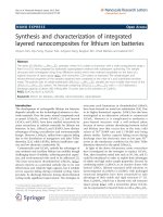
Figure 1 shows the SEM images of as-grown products with
different temperatures. It can be seen from Fig. 1a–c that
the products are all well-aligned at different growth tem-
peratures. The lengths of the CNTs are 46.6, 44.3, and
47.5 lm for 780, 820, and 860°C, respectively. It can be
seen that the surfaces of as-grown products are very clean
and free from impurity particles. As seen from Fig. 1d, the
CNTs grown at 860°C are open-ended, in fact the CNTs are
all open-ended in the range of 780–860°C. This is of vital
importance for their field-emission properties.
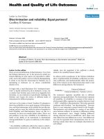
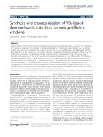
Figure 2 shows the TEM images of samples produced at
different temperatures. Figure 2a–c are typical TEM ima-
ges of CNTs prepared at 780, 820, and 860°C, respectively.
It can be seen from Fig. 2a–c that all these products possess
large TWI. The products are open-ended, which is in
agreement with the SEM observations. The typical tip
structure of as-obtained product is shown in Fig. 2d, and
the CNT is multi-walled CNT as shown in Fig. 2e. TEM
observations also reveal that the CNTs have bamboo-
shaped structures, which are similar to many reports about
N-doped CNTs [11, 13, 30, 31]. Bamboo-shaped CNTs are
usually formed because of the formation of 5-member ring
structures [32]. In present case, the formation of bamboo-
shaped CNTs is more possibly attributed to the doping
of nitrogen into CNTs because of the easy tendency of
5-member ring structure formation.
It can be seen from Fig. 2a–c that the diameter and TWI
become larger as temperature rises. The effect of temper-
ature on diameter in present study is similar to that reported
by Yadav, et al. [30], but no obvious temperature effect on
TWI was shown in their case. In present study, a possible
explanation for temperature effect on TWI is that larger-
sized catalyst particles lead to wider inner cavity of the
CNTs, and therefore larger TWI is obtained.
The TGA results of the as-grown products at different
temperatures (Fig. 3) show that the Fe encapsulation in
CNTs decreases as temperature rises. No remarkable
weight loss or gain occurs before 450°C in air, which
demonstrates that as-grown products possess high thermal
stability (see A ? B part of Fig. 3). When all the CNTs
and Fe metals are fully oxidized, the sample weight will
942 Nanoscale Res Lett (2010) 5:941–948
123
Fig. 2 TEM images of the as-grown products at different growth temperature: a–c are the low-magnification TEM images of a 780, 820, and
860°C sample, respectively; d, e are the high-magnification TEM images of a 860°C sample
Fig. 1 SEM images of as-grown products at different growth temperatures: a 780°C sample, b 820°C sample, c 860°C sample, d Open-ended
tips of the 860°C CNT sample
Nanoscale Res Lett (2010) 5:941–948 943
123
keep constant and shows a platform in the TGA curve
starting at about 650°C (see C ? D part). N-doped CNTs
turn into CO
2
or NO
x
, and Fe metal was transformed into
Fe
2
O
3
when they are fully oxidized in air. Thus, we can
obtain the Fe contents in products according to the weight
percentages of Fe
2
O
3
residues after TGA measurements. It
is found that the Fe content in the products grown at 780,
820, and 860°C are about 11.2, 8.6, and 3.9 wt%, respec-
tively. It is also found that Fe encapsulation in CNTs
decreased with temperature rising. A possible explanation
is that more Fe was carried out of reaction zone by carrier
gas with temperature rising.
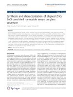
In order to find out the distributions of diameter and
TWI values, we measured 50 CNTs across a large sample
area in each product by TEM observations. The statistical
results of diameter values are shown in Fig. 4. The mean
diameters of CNTs prepared at 780, 820, and 860°C are
35.5, 44.6, and 64.0 nm, respectively. Obviously, the
diameters of CNTs increase as growth temperature rises
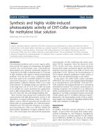
from 780 to 860°C. The statistical results of TWI values
are shown in Fig. 5. The mean TWI value of CNTs pre-
pared at 780, 820, and 860°C is 2.8, 3.1, and 6.2, respec-
tively. The CNTs prepared at 860°C have a larger TWI
than that of CNTs prepared by using trichlorobenzene as
carbon source *5.0 [16]. Apparently, the TWI value has a
similar temperature effect as that of diameters. This effect
can in turn provide a convenient way to control the
diameter and TWI of CNTs.
Fig. 3 Thermogravimetric analysis (TGA) of thin-walled open-ended
aligned N-doped CNT samples produced at three different
temperatures
Fig. 4 The diameter distributions of the CNTs produced at different temperatures: a 780°C, b 820°C, c 860°C
Fig. 5 The thin-walled index (TWI, defined as the ratio of inner diameter and wall thickness of a CNT) of the CNTs produced at different
temperatures: a 780°C, b 820°C, c 860°C
944 Nanoscale Res Lett (2010) 5:941–948
123
The XPS spectrum of the sample grown at 860°Cis
shown in Fig. 6. It can be seen that the product consists of
C (96.57 at.%), O (1.86 at.%), N (1.21 at.%), and a small
amount of Fe (0.18 at.%). It is obvious that the amount of
iron is quite different between XPS and TGA analysis,
because the former is surface analysis technique, while the
latter is bulk analysis one. The presence of oxygen peak
can be attributed to the prolonged exposure of the sample
in the air atmosphere [31, 33]. The full spectrum, C1s
spectrum and N1s spectrum are shown in Fig. 6a–c,
respectively.
The Raman spectra of the CNTs grown at different
temperatures are shown in Fig. 7. Raman spectroscopy has
been shown to be a perfect tool to evaluate the crystallinity
and the defects in carbon structures [30]. In Fig. 7, the
strong band around 1,585 cm
-1
is referred to the G-band,
and the strong band around 1,335 cm
-1
is referred to the
D-band. The D-band corresponds to the defects and dis-
ordered in the graphene sheets, and the G-band is attributed
to the well-graphitized carbon nanotubes [31]. The inten-
sity ratio of D-band and G-band (I
D
/I
G
) were found to
be *1 for all the CNTs grown at the three different tem-
peratures, as shown in Table 1. The large ratio of I
D
/I
G
is
mainly attributed to the nitrogen doping into the CNTs.
And the large I
D
/I
G
indicated that there were many defects
in the CNTs, which could act as effective emission sites
[14].
In order to evaluate the field-emission performance,
CNT samples were also grown on silicon wafers. Figure 8
displays the typical morphology of the as-prepared CNTs,
which grown homogeneously on silicon wafer or quartz
slide (see Fig. 8a). It can be seen that CNTs grown on
silicon wafer are well-aligned at all the three temperatures
from SEM observations (see Fig. 8b–d). The field-emission
measurements were carried out in a vaccum chamber of
2.2 9 10
-6
Torr with CNT samples on silicon wafer as
cathode.
Figure 9 shows the field-emission current (J) versus
applied electric field (E) characteristics of thin-walled open-
ended aligned N-doped CNTs grown at different tempera-
tures. Here, the turn-on field (E
to
) and threshold field (E
th
)
are defined as the electric fields when the emission current
densities reach at 10 lA/cm
2
and 1.0 mA/cm
2
, respectively
[5]. Field-emission values of different samples are shown in
Table 2. It can be seen that thin-walled open-ended aligned
Fig. 6 X-ray photoelectronic
spectra of CNTs grown at
860°C: a the full spectrum,
b C1s spectrum, c N1s spectrum
Fig. 7 Raman analysis of thin-walled open-ended aligned N-doped
CNT samples produced at three different temperatures
Table 1 The I
D
/I
G
ratio of the CNTs produced at the three different
temperatures
Temperature (°C) 780 820 860
I
D
/I
G
ratio 0.90 0.87 0.92
Nanoscale Res Lett (2010) 5:941–948 945
123
N-doped CNTs show excellent field-emission properties.
The CNTs prepared at 780, 820, 860°C show E
to
of
0.45, 0.35, and 0.27 V/lm, respectively; and E
th
of 0.60,
0.55, and 0.49 V/lm, respectively. This result illustrated
that thinner sidewalls are favorable to the improvement of
field-emission properties. From Table 2, one can see that
as-prepared thin-walled open-ended well-aligned N-doped
CNTs show much lower turn-on field and threshold field
than semiconductor nanomaterials (e.g., ZnO nanoneedle
arrays [34], ZnS Tetrapod Tree-like Heterostructures [35],
CuO nanoneedle arrays [36]), unfilled CNTs (e.g., Multi-
walled CNTs grown on a graphitized carbon fabric [37],
SWCNTs [38], aligned carbon nanotubes on plastic sub-
strates [18]), N-doped CNTs (e.g., aligned N-doped CNTs
[14], N-doped double-walled CNTs [39]), and FeNi-filled
CNTs [5]. The inset of Fig. 9 is the corresponding Fowler–
Nordheim (F–N) plots of different samples. The F–N plots
show linear behavior, which is similar to many other reports
[40, 41].
The field-enhancement factors (b) were calculated from
the slopes of F–N plots (S
F-N
) according to the following
equation [5]:
b ¼ Bu
3=2
d=S
FÀN
ð1Þ
where u is the work function of CNTs (=5.0 eV [5]), d is
the emitting distance (=2.0 mm), and B = 6.83 9 10
9
V/
(eV
3/2
m
-1
)[5]. The field-enhancement factors were cal-
culated and listed in Table 2, and the results showed that
the field-enhancement factors had been significantly
improved.
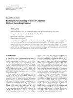
Free-standing membranes of thin-walled open-ended
aligned N-doped CNTs were also prepared. As shown in
Fig. 8 Morphology of the as-grown products: a photograph of the
products grown on silicon wafers and quartz slide, b SEM image of
CNTs grown at 780°C on silicon wafer, c SEM image of CNTs grown
at 820°C on silicon wafer, d SEM image of CNTs grown at 860°Con
silicon wafer
Fig. 9 Field-emission current (J) versus applied electric field (E)
characteristics of thin-walled open-ended aligned N-doped CNTs
grown at three different temperatures and the inset is the correspond-
ing Fowler–Nordheim plots of different samples
946 Nanoscale Res Lett (2010) 5:941–948
123
Fig. 8a, CNTs grow uniformly on quartz slide. Many
practical applications of CNTs require the transfer of
nanotube arrays onto other substrates [17]. Due to the Van
der Waals forces in the vertically aligned nanotube arrays,
the direct mechanical peeling of CNT membranes from the
substrate will damage the alignment of nanotubes in the
membranes [17]. It is still a challenge to obtain free-
standing CNT membranes without destroying their
alignment. In this study, the quartz slide growing CNTs is
put into 200 ml 10% HF solution for 12 h; then the CNT
membranes can be peeled from the quartz slide directly,
and then the CNT membranes was transferred into 100 ml
water easily (see Fig. 10a). Next, 2–3 ml ethanol was
added to the water, which made it easily for the flotation of
CNT membranes to the water surface [42]. We also found
that adding some ethanol to the water made it easier for the
Table 2 Field-emission data of different samples, here E
to
(V/lm) and E
th
(V/lm) are turn-on electric field and threshold electric field,
respectively; b is the field-enhancement factor
Samples E
to
(V/lm) E
th
(V/lm) b Data source
ZnO nanoneedle arrays 5.7 – 793 [34]
ZnS heterostructures 2.66 4.01 [2,600 [35]
Aligned N-doped CNTs 2.30 – – [14]
MWCNT 1.88 2.40 1.86 9 10
4
[37]
SWCNTs – 2.40 3,392 [38]
Aligned CNTs 1.13 2.25 6,222 [18]
N-doped DWCNTs *0.9 1.78 3,399 [39]
CuO nanoneedle arrays 0.85 – – [36]
FeNi-CNTs 0.30 0.65 2.48 9 10
4
[5]
ANCNT(780)
a
0.45 0.60 6.41 9 10
4
This study
ANCNT(820)
a
0.35 0.55 7.79 9 10
4
This study
ANCNT(860)
a
0.27 0.49 1.09 9 10
5
This study
a
ANCNT (860), ANCNT (820), and ANCNT (780) denote the samples prepared by acetonitrile at a growth temperature of 860, 820, and 780°C,
respectively
Fig. 10 CNT film peeled off and its SEM image: a CNT film peeled off from quartz slide and transferred into water, b CNT film spreading after
dropping some ethanol to water, c the free-standing film obtained after drying in oven, d SEM image of the as-obtained CNTs
Nanoscale Res Lett (2010) 5:941–948 947
123
spreading of CNT membranes, as it could be seen in
Fig. 10b. One can vividly see that as-obtained CNT
membranes were about 30 9 50 mm
2
as large as the size
of the quartz slide (the quartz slide is 30 9 50 mm
2
in
dimension) from Fig. 10c. It is shown in Fig. 10d that the
as-obtained CNTs are still well-aligned. The resulting free-
standing film can be easily transferred onto other substrates
(e.g., copper foil), which is a good news to their applica-
tions in different areas.
Conclusions
Thin-walled, open-ended, and well-aligned N-doped CNTs
were synthesized by using acetonitrile as a carbon source.
Temperature effects on diameter, TWI of as-produced
CNTs and Fe encapsulation in the CNTs were also inves-
tigated. The resulting CNTs grown at 860°C exhibited
much enhanced field-emission properties with a low turn-
on field (0.27 V/lm), threshold field (0.49 V/lm), and high
field-enhancement factor (1.09 9 10
5
). A simple method is
proposed to obtain free-standing membranes of this kind of
CNTs. The free-standing membranes may find their
applications in the supercapacitors, alkaline fuel cells,
lithium ion batteries, and heat conductive material.
Acknowledgments The authors are grateful to the financial support
from the National Natural Science Foundation of China (Grant No.
50902080, 50632040) and China Postdoctoral Science Foundation
(Grant No. 20090450021).
Open Access This article is distributed under the terms of the
Creative Commons Attribution Noncommercial License which per-
mits any noncommercial use, distribution, and reproduction in any
medium, provided the original author(s) and source are credited.
References
1. S. Iijima, Nature 354, 56 (1991)
2. R.P. Raffaelle, B.J. Landi, J.D. Harris, S.G. Bailey, A.F. Hepp,
Mater. Sci. Eng. B 116, 233 (2005)
3. Y. Chen, D.T. Shaw, L.P. Guo, Appl. Phys. Lett. 76, 2469 (2000)
4. M. Chhowalla, C. Ducati, N.L. Rupesinghe, K.B.K. Teo, G.A.J.
Amaratunga, Appl. Phys. Lett. 79, 2079 (2001)
5. R.T. Lv, F.Y. Kang, D. Zhu, Y.Q. Zhu, X.C. Gui, J.Q. Wei, J.L.
Gu, D.J. Li, K.L. Wang, D.H. Wu, Carbon 47, 2709 (2009)
6. H. Murakami, M. Hirakawa, C. Tanaka, H. Yamakawa, Appl.
Phys. Lett. 76, 1776 (2000)
7. T.J. Vink, M. Gillies, J.C. Kriege, H.J.J. van de Laar, Appl. Phys.
Lett. 83, 3552 (2003)
8. M.S. Wang, L.M. Peng, J.Y. Wang, C.H. Jin, Q. Chen, J. Phys.
Chem. B 110, 9397 (2006)
9. C.C. Chiu, T.Y. Tsai, N.H. Tai, Nanotechnology 17, 2840 (2006)
10. M. Glerup, J. Steinmetz, D. Samaille, O. Ste
´
phan, S. Enouz,
A. Loiseau, S. Roth, P. Bernier, Chem. Phys. Lett. 387, 193 (2004)
11. L.B. Hu, D.S. Hecht, G. Gruner, Nanotechnology 20, 465304
(2009)
12. M. Radosavljevic
´
, J. Appenzeller, Ph. Avouris, J. Knoch, Appl.
Phys. Lett. 84, 3693 (2004)
13. M. Terrones, P.M. Ajayan, F. Banhart, X. Blase, D.L. Carroll,
J.C. Charlier, R. Czerw, B. Foley, N. Grobert, R. Kamalakaran,
P. Kohler-Redlich, M. Ru
¨
hle, T. Seeger, H. Terrones, Appl. Phys.
A 74, 355 (2002)
14. Y.H. Lai, H.B. Lian, K.Y. Lee, Diamond Relat. Mater. 18, 544
(2009)
15. R.B. Sharma, D.J. Late, D.S. Joag, A. Govindaraj, C.N.R. Rao,
Chem. Phys. Lett. 428, 102 (2006)
16. R.T. Lv, F.Y. Kang, W.X. Wang, J.Q. Wei, J.L. Gu, K.L. Wang,
D.H. Wu, Carbon 45, 1433 (2007)
17. L.J. Ci, S.M. Manikoth, X.S. Li, R. Vajtai, P.M. Ajayan, Adv.
Mater. 19, 3300 (2007)
18. T.Y. Tsai, C.Y. Lee, N.H. Tai, W.H. Tuan, Appl. Phys. Lett. 95,
013107 (2009)
19. H.W. Gu, T.M. Swager, Adv. Mater. 20, 4433 (2008)
20. J.Y. Wang, Z. Jin, J. Cheng, Y. Li, J. Phys. Chem. C 113, 8132
(2009)
21. J. Chen, Y. Liu, A.I. Minett, C. Lynam, J.Z. Wang, G.G. Wallace,
Chem. Mater. 19, 3595 (2007)
22. K. Mukai, K.J. Asaka, T. Sugino, K.J. Kiyohora, I. Takeuchi,
N. Terasawa, D.N. Futaba, K.J. Hata, T. Fukushima, T. Adia,
Adv. Mater. 21, 1582 (2009)
23. N.T. Hong, J.H. Yim, K.H. Koh, S. Lee, P.N. Minh, P.H. Khoi,
J. Vac. Sci. Technol. B 26, 778 (2008)
24. A. Popp, O. Yilmazoglu, O. Kaldirim, J.J. Schneider, D. Pavlidis,
Chem. Commun. 22, 3205 (2009)
25. S.Y. Chew, S.H. Ng, J.Z. Wang, P. Nova
´
k, F. Krumeich, S.L.
Chou, J. Chen, H.K. Liu, Carbon 47, 2976 (2009)
26. J.M. Tang, M.E. Itkis, C. Wang, X. Wang, Y. Yan, R.C. Haddon,
Micro Nano Lett. 1, 62 (2006)
27. P.G. Whitten, A.A. Gestos, G.M. Spinks, K.J. Gilmore, G.G.
Wallace, J. Biomed. Mater. Res. 82B, 37 (2007)
28. R.T. Lv, S. Tsuge, X.C. Gui, K. Takai, F.Y. Kang, T. Enoki, J.Q.
Wei, J.L. Gu, K.L. Wang, D.H. Wu, Carbon 47, 1141 (2009)
29. G.W. Wu, A.Y. Cao, B.Q. Wei, C.L. Xu, J. Liang, D.H. Wu,
J. Tsinghua Univ. (Sci. Technol.) 42, 151 (2002)
30. R.M. Yadav, P.S. Dobal, T. Shripathi, R.S. Katiyar, O.N.
Srivastava, Nanoscale Res. Lett. 4, 197 (2009)
31. P. Ghosh, M. Subramanian, R.A. Afre, M. Zamri, T. Soga,
T. Jimbo, V. Filip, M. Tanemura, Appl. Surf. Sci. 255, 4611 (2009)
32. R.T. Lv, L. Zou, X.C. Gui, F.Y. Kang, Y.Q. Zhu, H.W. Zhu, J.Q.
Wei, J.L. Gu, K.L. Wang, D.H. Wu, Chem. Commun. 17, 2046
(2008)
33. Y.G. Lin, Y.K. Hsu, C.T. Wu, S.Y. Chen, K.H. Chen, L.C. Chen,
Diamond Relat. Mater. 18, 433 (2009)
34. J.S. Wang, C.S. Yang, P.I. Chen, C.F. Su, W.J. Chen, K.C. Chiu,
W.C. Chou, Appl. Phys. A 97, 553 (2009)
35. Z.G. Chen, J. Zou, G. Liu, X.D. Yao, F. Li, X.L. Yuan,
T. Sekiguchi, G.Q. Lu, H.M. Cheng, Adv. Funct. Mater. 18, 3063
(2008)
36. R.C. Wang, C.H. Li, Cryst. Growth Des. 9, 2229 (2009)
37. R.B. Rakhi, K. Sethupathi, S. Ramaprabhu, Carbon 46, 1656
(2008)
38. Y.K. Ko, J.X. Geng, S.G. Jang, S.M. Yang, T.W. Jeong, Y.W.
Jin, J.M. Kim, H.T. Jung, Carbon 47, 1555 (2009)
39. K.Y. Chun, H.S. Lee, C.J. Lee, Carbon 47, 169 (2009)
40. K.B.K. Teo, M. Chhowalla, G.A.J. Amaratunga, W.I. Milne,
G. Pirio, P. Legagneux, F. Wyczisk, D. Pribat, D.G. Hasko, Appl.
Phys. Lett. 80, 2011 (2002)
41. Y.M. Wong, W.P. Kang, J.L. Davidson, B.K. Choi, W. Hof-
meister, J.H. Huang, Diamond Relat. Mater. 14, 2078 (2005)
42. J.Q. Wei, H.W. Zhu, Y.H. Li, B. Chen, Y. Jia, K.L. Wang, Z.C.
Wang, W.J. Liu, J.B. Luo, M.X. Zheng, D.H. Wu, Y.Q. Zhu, B.Q.
Wei, Adv. Mater. 18, 1695 (2006)
948 Nanoscale Res Lett (2010) 5:941–948
123