báo cáo hóa học:" Research Article Planning of Efficient Wireless Access with IEEE 802.16 for Connecting Home Network to the Internet" potx
Bạn đang xem bản rút gọn của tài liệu. Xem và tải ngay bản đầy đủ của tài liệu tại đây (4.55 MB, 12 trang )
Hindawi Publishing Corporation
EURASIP Journal on Wireless Communications and Networking
Volume 2010, Article ID 625414, 12 pages
doi:10.1155/2010/625414
Research Article
Planning of Efficient Wireless Access with IEEE 802.16 for
Connecting Home Network to the Internet
Pichet Ritthisoonthorn,
1
Kazi M. Ahmed,
1
and Donyaprueth Krairit
2
1
School of Engineering and Technology, Asian Institute of Technology (AIT), P.O. Box 4, Klong Luang, Pathumthani 12120, Thailand
2
School of Management, Asian Institute of Technology (AIT), P.O. Box 4, Klong Luang, Pathumthani 12120, Thailand
Correspondence should be addressed to Pichet Ritthisoonthorn,
Received 11 June 2009; Revised 10 January 2010; Accepted 19 February 2010
Academic Editor: M
´
airt
´
ın O’Droma
Copyright © 2010 Pichet Ritthisoonthorn et al. This is an open access article distributed under the Creative Commons Attribution
License, which permits unrestricted use, distribution, and reproduction in any medium, provided the original work is properly
cited.
The emergence of IEEE802.16 wireless standard technology (WiMAX) has significantly increased the choice to operators for the
provisioning of wireless broadband access network. WiMAX is being deployed to compliment with xDSL in underserved or lack of
the broadband network area, in both developed and developing countries. Many incumbent operators in developing countries are
considering the deployment of WiMAX as part of their broadband access strategy. This paper presents an efficient and simple
method for planning of broadband fixed wireless access (BFWA) with IEEE802.16 standard to support home connection to
Internet. The study formulates the framework for planning both coverage and capacity designs. The relationship between coverage
area and access rate from subscriber in each environment area is presented. The study also presents the throughput and channel
capacity of IEEE802.16 in different access rates. An extensive analysis is performed and the results are applied to the real case
study to demonstrate the practicality of using IEEE 802.16 for connecting home to Internet. Using empirical data and original
subscriber traffic from measurement, it is shown that the BFWA with IEEE802.16 standard is a capacity limited system. The
capacity of IEEE802.16 is related to different factors including frequency bandwidth, spectrum allocation, estimation of trafficper
subscriber, and choice of adaptive modulation from subscriber terminal. The wireless access methods and procedures evolved in
this research work and set out in this paper are shown to be well suited for planning BFWA system based on IEEE802.16 which
supports broadband home to Internet connections.
1. Introduction
The appearance of advanced digital technologies and the
proliferation of smart appliances in home including the
availability of low cost communication technology have
significantly increased the need of an efficient home network.
A home network interconnects several consumer electronic
(CE) products and systems for information access and
control. Contents which are accessed through these products
by homeowner may come from many sources of CEs such as
digital audio-video (A/V) inside home and external sources
like streaming video over the Internet network. Thus, a
smart home network definitely requires a connection with
other networks in order to access contents and information
over the Internet network. It is implied that a future home
network requires higher bandwidth for sending, for example,
real time VoIP and streaming video applications between
smart CEs. For this reason, a future smart home is inevitably
heading to support broadband services.
In order to provide the broadband services, the con-
sideration of home network has to be extended on the
upper network level, so called as access network. The
requirement of higher bandwidth is necessary for the access
network for interfacing with the home gateway. There are
many broadband technologies proliferating and commer-
cially available in the access communication networks. xDSL
(digital subscriber line) remains by far the most popular
broadband access technology with the major market share.
The basic problem with xDSL is a distance limitation
due to signal attenuation. The maximum bandwidth of
xDSL is limited by the distance of the user from the local
exchange, quality of cable, and amount of crosstalk in
2 EURASIP Journal on Wireless Communications and Networking
the cable. The bandwidth limitation of xDSL causes the
growth rate of wired broadband technologies to decrease
in many countries due to the strong growth in fiber-to-
the-home (FTTH) and wireless access technologies. FTTH
technology is the most innovative technology which can
provide a limitless bandwidth per subscriber at a distance
up to 20 kilometers. This technology is very suitable but the
fundamental problems are the installation cost of fiber and
the CPE cost, which is much higher than the cost of DSL
modem. As a consequence, broadband wireless technologies
are gradually replacing wired technologies [1].
Two wireless broadband technologies under Interna-
tional Mobile Telecommunications 2000 (IMT-2000) are
wideband code division multiple access (WCDMA) and
cdma2000. WCDMA uses DSSS (direct sequence spread
spectrum) to spread the signal over a 5 MHz spectrum
and provides data rate of 384 kbps, and up to 2 Mbps.
cdma2000 evolutions for data handling capabilities have
come in the form of cdma2000-3x. cdma2000-3x can
provide data rate of 2–4 Mbps. In 2007, the International
Telecommunication Union (ITU) approved the inclusion
of orthogonal frequency division multiple access (OFDMA)
technology in IMT-2000 set of standards [2]. After the
inclusion of OFDMA-based technology, IEEE802.16, which
also uses OFDMA technology, becomes more competitive
with 3G cellular technologies. IEEE802.16, also known as
WiMAX (Worldwide Interoperability for Microwave Access)
as defined by the WiMAX forum, is getting attention in
developed and developing countries for broadband access
due to low cost, rapid deployment, and advanced features of
OFDMA technology. As a result, numerous operators, espe-
cially in developing countries are considering IEEE802.16
to compliment and compete with ADSL in areas that are
underserved or lacking in broadband service. Sooner or
later, IEEE802.16 will become a realistic broadband fixed
wireless access (BFWA) system. Nonetheless, the analysis of
cost efficiency for BFWA system is not clarified. Such dubiety
can be found in system cost structure of broadband wireless
access given that the system cost of broadband wireless access
is directly proportional to the user data rate, or equivalently,
the cost per transmitted [3]. The relationship between system
cost and user data rate drives a great challenge to operators
in attempting to provide an affordable price broadband
wireless access network. In short, network planner devotes
to optimize an efficient network planning with the target
on lowering the system cost for broadband wireless access
network.
Lowering the cost of broadband wireless access derives
from many alternatives, for example, sharing network
infrastructure, lowering the complexity of equipment and
technologies [4]. For sharing network infrastructure, it is too
ideal to implement in the competitive market. Hence, the
practical approach has to rely on efficient planning.
There have been quite a few works involving the planning
issues of IEEE802.16, as deployed in developed countries.
For examples, the work in [5–7] dealt with broadband
wireless access network without any specific detail design.
In the previous works, network scales mainly derived from
market assumptions and traffic demand solely obtained from
estimations. In addition, there is hardly any work combining
network planning and cost issues together for IEEE802.16
as a BFWA system. For realizing future large scale access
network in specific area, especially for high-speed Internet
access in urban area as well as for bridging the digital divide
in a developing country, no work is available. In order to
address these deficiencies, we present an efficient planning
method of BFWA systems with IEEE802.16 standard as a
future BFWA for connecting smart home network to the
Internet. In this research, an efficient network planning of
BFWA system is proposed for lowering the cost of wireless
access network. We choose IEEE802.16 standard as a selected
technology since it has a high potential for BFWA system.
We have developed the planning model using common
spreadsheet program to estimate path loss and channel
throughput of IEEE802.16. A spreadsheet program provides
a simple method of trying different parameter values to
determine their effect on network scale. Together with traffic
demand from our measurements in the real network, we
capture the number of access points for dimension purpose.
Finally, the model is validated by applying to the Bangkok
area, the capital of Thailand, as a real case under study.
The remainders of this work are described as follows.
In Section 2, we briefly explain the network infrastructure
and the operation principle of BFWA systems based on
IEEE802.16 standard. Then we discuss the BFWA network
planning in Section 3.InSection 4, we present the key results
from analysis and extend results to the case study. Finally,
conclusion is presented in Section 5.
2. Wireless Access and IEEE 802.16 Standard
Traditionally, the most difficult segment of the network to be
built and the least effective cost to be maintained have proven
to be the access network regardless of a developing or a devel-
oped economy. Nevertheless, the availability of broadband
wireless technologies has the possibility to lower the cost
and fast deployment while providing higher bandwidth than
traditional copper cable. The following subsections provide
some groundwork of network infrastructure, alternative
broadband access technologies, role of BFWA system and
technical standard of IEEE802.16.
2.1. The Infrastructure of Telecommunication Network. The
telecommunication networks infrastructures are commonly
divided into three major segments [8]. The first segment is
transport network, which provides connection between net-
work operator and service provider. This network is mainly
based on transport technologies, for example, DWDM
or IP transport network. The second segment is access
network, formerly known as local loop, consisting of the so-
called last mile connections between end user and network
operator. The last segment is home network, which provides
interconnections inside a household, allowing services to be
distributed inside house as well as to the public network
through access network. A home network interconnects CE
devices and systems, and available contents, for example,
music, video, and data [9, 10]. We expect that a future
EURASIP Journal on Wireless Communications and Networking 3
Service
provider
Tr an sp o rt
network
Network
operator
Access
network
End user
Home
network
CEs
Figure 1: Telecommunication network infrastructure for offering service.
home network is likely to be composed of wireless networks
with different data rates, link characteristics, and access
protocols. Figure 1 depicts the telecommunication networks
infrastructures required to fulfill the service deployment.
2.2. Alternative Broadband Access Technologies. In general
broadband access technologies can be classified into two
groups: wired technologies or wireless technologies [1].
Wired technologies rely on a direct physical connection to
the subscriber’s residence. Many broadband technologies
such as DSL and FTTH have evolved to use an existing
infrastructure of subscriber connection as the medium for
communications. Wireless broadband technologies refer to
the communication using radio link as a medium to transmit
signals between sites and an end-user receiver. Wireless
broadband access technologies are proliferating such as
WCDMA, cdma2000, IEEE802.11 or Wi-Fi, and IEEE802.16
or WiMAX. The main broadband access technologies are
detailed in the followings [11].
2.2.1. Digital Subscribe r Line. DSL is a copper-based broad-
band technology for the local loop that relies on digital tech-
nology. There are different DSL technologies, for example,
ADSL, VDSL, and ADSL2+. Data rates depend on versions
of DSL, quality of cable, amount of cross talk in the line
and cable length. For example, ADSL downlink data rate is
6.3 Mbps for the loop length of 3.6 km, and is 1.5 Mbps for
the loop length of 5.4 km. Uplink data rate is 640 kbps.
2.2.2. Fiber to the Home. FTTH is the fiber-based technology
providing more bandwidth per subscriber. FTTH can deliver
data streams of up to 1Gbps and operate at a distance of
up to 20 kilometers. Although this technology is developing
rapidly, yet installation cost for fiber and CPE cost of receiver
are prohibitively high.
2.2.3. Wireless Fidelity (Wi-Fi). Wi-Fi has been widely
deployed and popular among hot spots. Currently, Wi-Fi
platforms include 802.11a, 802.11b, and 802.11g. Maximum
possible distance from the access point is roughly 100 meters
for indoor and 300 meters for outdoor environment.
2.2.4. WiMAX. WiMAX is the most challenging technol-
ogy emerging recently for both high density metropolitan
and remote areas network applications. WiMAX platforms
include IEEE802.16d or fixed-WiMAX and IEEE802.16e or
mobile-WiMAX. The WiMAX is designed to provide a
communication path between a subscriber site and a core
network. At each access point, WiMAX technology could be
added on to increase mobility of users.
2.2.5. 3G Cellular. 3G technologies use cellular networks to
enable Internet connection from mobile phones. In order
to support 3G systems, infrastructure changes, for example,
new base station add-on and software upgrade, will be
required on the existing cellular networks, as well as new
handsets. The maximum data rate for WCDMA provides
data rate of 384 kbps and up to 2 Mbps while cdma2000 can
provide data rate 2–4 Mbps.
The technical comparison of broadband technologies is
provided in Tab l e 1. The table indicates that each technology
has its own merits and demerits. The wired broadband
technologies operating over existing copper are bandwidth
limited except FTTH, which has unlimited bandwidth but
it is very costly of deployment. On the other hand, wireless
broadband technologies are bandwidth limited, but the
amount of available radio spectrum band is wide. The
comparison between 3G technologies and IEEE802.16 shows
that 3G technologies use soft handoff for voice, but this
advantage disappears for data-centric applications. These
advantages are not sufficient to overcome the advantages of
OFDMA-based technology like IEEE802.16. As data traffic
continues to grow, there will be an increasing need to offload
data from 3G to OFDMA-based network optimized for
data. IEEE802.16 is an excellent complement to other wires
technologies, for example, Wi-Fi or WCDMA. The decision
of ITU to incorporate OFDMA technology to IMT2000 is
an evidence toward the further adapting of IEEE802.16.
However, the maturity of IEEE802.16 is yet to be developed
andexpectedtotakesomemoretime[2].
The market efficiency of IEEE802.16 compares to other
technologies, especially 3G, indicates that the deployment of
IEEE802.16 in developed countries involves very high invest-
ment. This is due to the deployment of DSL and 3G tech-
nologies are matured in developed countries. IEEE802.16,
as a new technology, has a lot of uncertainties. The detailed
comparisons of market efficiency IEEE802.16 is provided in
[12].
The market analysis indicates that IEEE802.16 has poten-
tial for the broadband service provisioning. In developed
countries, the value proposition of IEEE802.16 mainly
concentrates on extending the coverage of Wi-Fi and can
be deployed as a complement service to 3G networks. In
developing countries, IEEE802.16 is well-suited for the areas
that are underserved or lacking in broadband service. The
value proposition of IEEE802.16 in developing countries is
to provide an economical, flexible, and fast deployed solution
to improve the Internet access. The detailed comparisons of
market potential and benefit between IEEE802.16 and other
technologies are provided in [13].
2.3. The Role of Broadband Fixed Wireless Access System. The
ITU defines wireless access system (WAS) as end user radio
4 EURASIP Journal on Wireless Communications and Networking
Table 1: Comparison of alternative broadband access technologies.
Technology
Bandwidth
Capacity
(max)
Coverage (max) Pros Cons
Wired
ADSL
6.3 Mbps 3.6 km Uses existing copper line Limited bandwidth
ADSL2+
26 Mbps 0.3 km Uses existing copper line
Bandwidth is limited by
distance
VDSL
52 Mbps 0.3 km Uses existing copper line Requires fiber feeder
FTTH
1Gbps 20km
Bandwidth growth through
WDM possible
Requires new fiber plant
Wireless
3G (WCDMA& cdma2000)
2–4 Mbps Wide area
Use some existing cellular
network
Costly spectrum
expenditure
Wi-Fi
54 Mbps 100 m Uses unlicensed spectrum Security issue
WiMAX
75 Mbps
50 km (LOS)
8 km (NOLS)
Uses NLOS Self installation
Cell sized is limited in
NLOS
connections to public or private core networks. In the ITU-R
Recommendation F.1399-1 (5/2001), WAS is classified into
three categories [14]. The first category, mobile wireless
access (MWA), is described as a wireless access application in
which the location of the subscriber terminal (ST) is mobile.
The second category, nomadic wireless access (NWA), is a
wireless access application in which the location of the ST
may be in different places but it must be stationary while
in use. The last category, fixed wireless access (FWA), is a
wireless access application in which location of the ST, and
the network access point (AP) to be connected to the ST are
fixed.
BFWA systems are considered as the real competitor
to wired broadband technology. BFWA can reach those
users outside the geographical or financial scope of DSL
or cable, and can offer more capacity. Advantages of using
BFWA for broadband access over wired alternatives include
better handling of multicasting service, and the potential
for flexible and rapid deployment [15]. Figure 2 depicts the
architecture of BFWA system for connecting home access
point.
2.4. IEEE802.16 Standard for BFWA System. The IEEE802.16
family of standards promises to deliver high data rate over
large areas to a large number of users in near future. The first
standard, completed in 2001 and finalized in 2004, defines
the air interface and medium access control (MAC) protocol
for IEEE802.16. The IEEE802.16 standard defines two layers:
MAC protocol and physical layer (PHY) [16].
The IEEE802.16 MAC protocol is designed for point
to multipoint broadband wireless access applications. It
addresses the need for very high bit rates, both uplink
and downlink. Access and bandwidth allocation algorithms
accommodate hundreds of terminals per channel, with
terminals that may be shared by multiple end users. The
services required by these end users are varied in their nature
and include legacy time division multiplex (TDM) voice and
data, IP connectivity, and packetized VoIP. To support this
variety of services, the IEEE802.16 MAC accommodates both
continuous and bursty traffic. The IEEE802.16 access system
provides more efficiency when presented with multiple
connections per terminal, multiple QoS levels per terminal,
and a large number of statistically multiplexed users. Along
with the fundamental task of allocating bandwidth and
transporting data, the MAC includes a privacy sublayer that
provides authentication of network access and connection
establishment to avoid theft of service, and it provides key
exchange and encryption for data privacy [17].
Air interface for IEEE802.16 was designed to operate
into two frequency ranges: 10–60 GHz and 2–11 GHz. In
the design of the PHY specification for 10–66 GHz, line of
sight (LOS) propagation is deemed as a practical neces-
sity. With this condition assumed, single-carrier modu-
lation is selected, and the air interface is designated as
“WirelessMAN-SC.” [18].
The 2–11 GHz bands, both licensed and license-
exempted, are addressed in IEEE802.16a. Design of the
2–11 GHz physical layer is driven by the need for NLOS
operation. Because residential applications are expected,
rooftops may be too low for a clear sight line to an AP
antenna, possibly due to obstruction by trees. Therefore,
significant multipath propagation must be expected [19].
3. BFWA Network Planning
The efficient BFWA network depends on the system of
network planning. For achieving efficient network planning
purpose, planners must target on subscribers and ensure that
they are in the area of service. Moreover, the planner has
to be assured that network has sufficient capacity to handle
the traffic from users. Planning BFWA network or any radio
network, therefore, requires comprehensive coverage and
capacity planning. The key result of network planning is an
approximate number of access points and hardware to meet
the user’s demand as same as operator’s requirement. The
network can be either coverage limited or capacity limited.
EURASIP Journal on Wireless Communications and Networking 5
Access point (AP)
Tx/Rx
Multiplexing and coding
Internet Telephony
Broadcast TV
etc
Subscriber terminal (ST)
Tx/Rx
Multiplexing and coding
Figure 2: BFWA system providing a mix of service to home network.
The number of access points requirements is dimensioned to
the following model [20]:
N
AP
= max{N
AP-co
, N
AP-ca
},(1)
where N
AP-co
is the number of AP acquired from coverage
planning, and N
AP-ca
is the number of AP derived from
capacity planning.
3.1. Coverage Planning. Theprimaryobjectiveofcoverage
planning is to estimate the needed number of APs to
fulfill the coverage of all subscribers in a given service
area. Coverage planning of BFWA network requires the
knowledge of radio propagation model for predicting the
losses between transmitters and receivers path. The path loss
represents the combined effects on signal attenuation due
to the free space loss, reflection, diffraction and scattering,
and so forth. The propagation of radio frequency depends
on the physical environment, therefore, we have to define the
service area and select appropriate radio propagation model
to predict the path loss. The accuracy of path loss prediction
can greatly affect the estimated cell range, which in turn
determines the number of AP needed to achieve a coverage
area in the network. There are many radio propagation
models used to predict the path loss in wireless network.
The classifications and characteristics of radio propagation
models are empirical, deterministic and stochastic model,
which are detailed in [21, 22].
Among those mentioned models, empirical models
are most appropriate for dimensioning wireless network
since it is simple and sufficiently accurate in the limited
knowledge of environment data. HATA model, COST-231
HATA (one of the European Science Foundation “COop-
eration in the field of Science and Technology research”
Actions; and the Stanford Univer-
sity Interim (SUI) are example of empirical models [21–
23]. All these models predict the mean path loss as function
of various parameters, for example, distance and antenna
height. We select propagation loss models based on the study
in [23],andapplytothisstudywhichissummarizedin
Ta bl e 2 .
3.1.1. Link Budget. The link budget is a tabulation of all gains
and losses in the link that are added in order to deliver the
mean signal level at the receiver. The term link budget is
often used to indicate the allowance path loss, which in turn
Table 2: Propagation loss models parameter.
Environment Path loss model AP antenna height (m)
Urban ECC-33 30
Suburban IEEE 802.16 (SUI-B) 40
Rural IEEE 802.16 (SUI-C) 60
is used to determine the cell range of AP. The formulas are
necessary to calculate the values in the link budget which use
basic mathematical functions and are very straightforward
to implement in commonly available spreadsheet program.
A simple link budget calculation model implemented in this
study is depicted in Tab le 3 .
3.1.2. Cell Range Estimation. The next step of coverage plan-
ning is to estimate the cell range and cell coverage area. The
cell range can be calculated using predefined propagation
loss models in Ta bl e 2 . The propagation loss models describe
the average signal propagation in that environment, and
convert the maximum allowanced propagation loss in dB
to the maximum cell range in distance. By applying AP
antenna height designated in Tab l e 2, ST antenna height of
6 meters, and carried frequency of 3.5 GHz, the closed form
for prediction of the allowance path loss in urban, suburban
and rural are given by (2), respectively.
L
Urban
= 132.64 +
29.83 + 4.78 log
(
d
)
log
(
d
)
,
L
Suburban
= 121.22 + 41.67 log
(
d
)
,
L
Rural
= 111.57 + 36.33 log
(
d
)
,
(2)
where d is the distance between transmitter and receiver in
kilometer.
By assuming the cell shape as hexagonal, the area covered
by a single cell is given by [24]
A
cell
= 2.6d
2
. (3)
In this study the cell range is calculated for the downlink,
which is expected to support much higher data rates than the
uplink. Therefore, this link will limit the coverage range.
3.1.3. Number of AP Acquired from Coverage Planning. The
result from coverage planning is the expected number of AP
6 EURASIP Journal on Wireless Communications and Networking
Table 3: Link budget calculation model.
User data rate in kbps 1.024
Required Eb/No 9.3
System element Unit Uplink Downlink Formula
Transmitter ST AP
Maximum Tx power in Watt Watt 0.25 1.58
Maximum Tx power in dBm dBm 23.98 31.99 A
Cable loss & Insertion loss dB 0.00 3.30 B
Antenna Tx gain dBi 2.00 18.00 C
EIRP dBm 25.98 46.69 D
= A −B+C
Receiver AP ST
Thermal noise density dBm/Hz
−174.00 −174.00 E
Receiver noise figure dB 5.00 5.00 F
Receiver noise density dBm/Hz
−169.00 169.00 G = E+F
Receiver noise power dBm
−103.16 −103.16 H = G + 10 log(3840000)
Interference margin dB 3.00 3.00 I
Receiver interference power dBm
−103.18 −103.18 J = 10 log(10
∧
(H + I)/10 −10
∧
(H/10))
To t a l e ffective noise + interference dBm
−100.16 −100.16 K = 10 log(10
∧
(h/10 + 10
∧
(J/10))
Processing gain dB 5.74 5.74 L
= 10 log(3840/user data rate)
Required Eb/No dB 9.30 9.30 M
Receiver sensitivity level dBm
−96.60 −96.60 N = M −L+K
Antenna Rx gain dBi 18.00 0.00 O
Cable loss dB 2.00 0.00 P
Fading margin dB 4.00 0.00 Q
Maximum allowable path loss dB 134.58 143.28 R = D −N+O−P −Q
for a given service area. The number of AP based on coverage
design is obtained from the following equation
N
AP-co
=
A
service
A
cell
,(4)
where A
service
is a given service area.
3.2. Capacity Planning. The main purpose of capacity plan-
ning is to estimate the needed number of APs to fulfill the
traffic demands of subscribers in a given service area. BFWA
systems are often deployed in point to multipoint cellular
fashion where a single AP provides wireless coverage to a
collection of STs within coverage area.
3.2.1. Channel Throughput Estimation. The channel
throughput (T) is defined as the aggregate cell payload, that
is, the peak useful data rate. The useful data rate is shared
between all active users who are connected to the same AP.
The aggregate cell payload for IEEE802.16 is given by [25]
T
=
6
7
k ·2
m
·B
c
(
2
m
+1
)
·
R
c
,(5)
where k is the bits per symbol for the modulation being used,
m is the cyclic prefix, m
={2, 3,4, 5}, B
c
is the channel
width of IEEE802.16, and R
c
is the overall code rate for
the modulation being used in ST. Tab le 4 shows bit per
symbol and overall code rate in different types of modulation
schemes [24].
Table 4: Bit per symbol and overall code rate.
Modulation type Bit per symbol, k Overall code rate, R
c
BPSK 1/2 1 1/2
QPSK 1/2 2 1/2
QPSK 3/4 2 3/4
16 QAM 1/2 4 1/2
16 QAM 3/4 4 3/4
64 QAM 2/3 6 2/3
64 QAM 3/4 6 3/4
Investigation of the channel throughput of IEEE802.16
BFWA system deals with the complex parameters of OFDM
technology and adaptive modulation. For the sake of sim-
plicity, we implement throughput calculation model by a
convenient way using common spreadsheet program. The
implementation of channel throughput calculation model is
depicted in Tab le 5 . The first nine rows represent the input
values for calculation and the last two rows represent the
result output from the model.
Spectrum efficiency (SE) is the ratio of channel through-
put and bandwidth of channel, SE
= T/B
c
which is given by
[2]
SE
=
6
7
k ·2
m
(
2
m
+1
)
·
R
c
. (6)
EURASIP Journal on Wireless Communications and Networking 7
Table 5: Channel throughput calculation model.
Item Value Descriptions
Input data
Channel size in MHz 14 Channel width (1.75, 3.5, 7 or 14)
Cyclic exponent
∗
5 Repeat symbol fraction (2–5)
BPSK-1/2 5
Distribution of modulation in ST (%)
QPSK-1/2 2.5
QPSK-3/4 2.5
16QAM-1/2 25
16QAM-3/4 25
64QAM-2/3 20
64QAM-3/4 20
Checksum 100
Output data
n 1.14 Sampling factor in constant value
Fs 16.00 Sampling frequency in MHz
f 62.51 Spacing of subcarrier in MHz
Tb 16.00 Inverse of subcarrier spacing in μsec
Ts 16.00 Symbol time in μsec
T 34.53 Channel Throughput in Mbps
SE 2.47 Spectrum efficiency in b/s/Hz
Note:
∗
Cyclic exponent is a dimensionless unit.
1473.51.75
Channel width (MHz)
T3 at high speed access scenario
T2 at medium speed access scenario
T1 at low speed access scenario
0
5
10
15
20
25
30
35
40
45
Channel throughput (Mb/s)
Figure 3: Channel throughput and channel size for each access
scenario.
3.2.2. Channel Capacity Estimation. Once we determine the
radio spectrum and the RF channel size, the next important
step of capacity planning is to determine the channel capacity
of IEEE802.16. The channel capacity is the active number of
subscribers in a single channel. The maximum number of
subscribers that can be supported by a channel is given by
c
=
T
R
d
,(7)
where R
d
is a peak traffic demand per user in kb/s.
3.2.3. Number of AP Acquired from Capacity D esign. The
number of AP is derived from the ratio of the expected
number of subscribers in the service area to the maximum
number of subscribers supported by single AP, and given by
N
AP-ca
=
N
service
c
,(8)
where N
service
is the number of users to be serviced.
By the substitution of (7) into (8), the required number
of AP for capacity design is obtained by
N
AP-ca
=
R
d
T
N
service
. (9)
4. Results
In this section, we investigate the system planning of BFWA
based on IEEE802.16 standard using calculation models from
previous section. We extend our study by applying results
from analysis to the case study. The case study is within
the area of Bangkok Metropolitan Administration (BMA),
Thailand.
4.1. Key Input for Analysis
4.1.1. System Design Parameters. We define parameters of
IEEE802.16 BFWA system into two groups. The first group
is the generic parameters of IEEE802.16 standard. The
parameters of this group are operating frequency, channel
width, and maximum transmit power. The second group is
the design parameters which are specific to the radio design
such as antenna height of AP and ST. These two groups of
parameters must be defined prior to analysis of both coverage
and capacity. These parameters are derived from commercial
8 EURASIP Journal on Wireless Communications and Networking
Table 6: Design parameters.
Parameters Value
Frequency range (GHz) 3.5
Channel width (MHz) 1.75, 3.5, 7.0, and 14
Maximum transmit power (W) 3.2
Micro cell AP antenna height (m) 40
Macro cell AP antenna height (m) 60
Subscriber terminal antenna height (m) 6
9.68.47.264.83.62.41.20.1
Distance (km)
ECC-33 model
SUI-B model
SUI-C model
FSL
100
120
140
160
180
Maximum path loss (dB)
Figure 4: Relation of path loss and cell range of each path loss
model.
products existing in the market. Ta bl e 6 shows the system
parameters of IEEE802.16 as BFWA system.
4.1.2. Modulation Distribution Assumption. In the principle
of adaptive modulation, the type of modulation being used
by ST strongly depends on the signal-to-noise ratio at
the receiver end. The signal-to-noise ratio relates to the
distance between transmitter and receiver. Normally, the
main purpose of engineering design is to install the AP at
the location where the number of subscribers is maximum.
Practically, not all subscribers are covered by single AP. We,
therefore, need to assume the location of subscribers relating
to AP. The criterion for assumption is the subscribers who
are close to AP receives more signal-to-noise ratio than
distant subscribers. Under such a situation, ST selects a
higher bit per symbol modulation scheme. Based on such
criterion, we assume the location of subscribers to the AP
through the distribution of modulation scheme being used
in ST. The assumption of modulation distribution implies
the subscriber data rates access to the network. We define the
subscriber data access into three scenarios. The first scenario
is the low speed data rate, where modulation scheme being
used in ST is dominated by BPSK. This scenario describes
the subscriber who is far from AP. The second is the medium
speed, where modulation scheme in ST is moderated. The
last scenario is the high speed data rate, where 64-QAM
is a dominant modulation scheme in ST. This scenario
describes the subscriber who is close to AP. Tab le 7 shows
the assumption of modulation distribution in ST. We will
use medium speed data rate as a baseline case for future
comparison and analysis.
1473.51.75
Channel width (MHz)
A1 urban area
A2 suburban area
A3 rural area
0
2
4
6
8
10
12
14
16
Cell area (km
2
)
(a) Cell area in different types of environment area
1473.51.75
Channel width (MHz)
A4 low speed access scenario
A5 medium speed access scenario
A6 high speed access scenario
0
2
4
6
8
10
12
14
Cell area (km
2
)
(b) Cellareaindifferent access scenarios
Figure 5: Relation of coverage area of single cell to access rate and
type of environment areas.
Table 7: Assumption of modulation distribution in subscriber
terminal.
Access scenario BPSK QPSK 16-QAM 64-QAM
Low Speed 0.8 0.1 0.05 0.05
Medium Speed 0.01 0.48 0.5 0.01
High Speed 0.01 0.05 0.1 0.84
4.1.3. Traffic Estimation per Subscriber. The next step of
the capacity planning is to determine the trafficdemand
of each subscriber. Generally, planners use statistical model
for dimensioning access network. Contradictory with other
works, in this research we use the empirical data measuring
from subscriber traffic of operational network [26], as shown
in Ta bl e 8 .
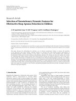
4.2. Key Results from Analysis. The planning procedures
begin with the calculation of the channel throughput of
IEEE802.16. Based on the assumption of modulation distri-
bution in ST and the available channel width, the channel
throughput T can be computed using throughput calculation
EURASIP Journal on Wireless Communications and Networking 9
Table 8: Traffic per subscriber.
Access
area
Peak uplink
(kb/s)
Peak
downlink
(kb/s)
Average
uplink (kb/s)
Average
downlink
(kb/s)
Urban 360.73 596.94 292.5 397.23
Suburban 56.4 322.21 73 107.94
Rural 85.03 144.1 12.63 75.36
Table 9: Throughput and path loss for different channel sizes.
Channel width
(MHz)
Throughput
(Mb/s)
Maximum path
loss (dB)
1.75 2.75 133.39
3.5 5.51 130.98
7.0 11.01 127.97
14.0 22.02 124.88
Table 10: Cell Range and Path Loss of Medium Access.
Channel
width
(MHz)
Maximum
path loss
(dB)
ECC-31
(m)
SUI-B
(m)
SUI-C
(m)
1.75 133.39 600 1,300 2,400
3.5 130.98 500 1,100 2,000
7.0 127.97 350 900 1,700
14.0 124.88 300 700 1,400
model of Ta bl e 5 . Figure 3 demonstrates the results of
channel throughput. The results show that RF channels with
higher channel width increase the channel throughput. RF
channel throughput also depends on the speed of data access
from subscriber. The channel throughput that configures
as high speed access has more channel throughput than
a lower access. The description of a high access data rate
contributes to RF channel throughput is mainly from the
overhead information contained in the radio packet between
ST and AP.
4.2.1. Channel Throughput. See Figure 3.
4.2.2. Cell Range. The cell range can be estimated by insert-
ing the channel throughput into the link budget calculation
model in Ta ble 3 . We obtain the maximum allowance path
loss between AP and ST. Ta bl e 9 shows the results of
maximum allowance path loss in a variety of channel width.
We select the empirical radio path loss models in Ta bl e 2
for prediction of the path loss between AP and ST. Equations
(2) are used for converting the path loss into distance.
Figure 4 shows the results of maximum path loss predicted by
each model plotted against distance. The results of cell range
of particular channel width for medium access scenario
estimated by (2) are shown in Ta bl e 1 0. The results indicate
that cell size of remote open area is bigger than the cell size
of urban dense area.
1473.51.75
Channel size (MHz)
c1 urban area
c2 suburban area
c3 rural area
0
50
100
150
200
250
300
350
Number of active subscriber
per channel
(a) Channel capacity by access scenario
1473.51.75
Channel width (MHz)
c4 low speed access scenario
c5 medium speed access scenario
c6 high speed access scenario
0
20
40
60
80
100
120
140
Number of active subscriber
per channel
(b) Channel capacity by environment
Figure 6: Channel Capacity of IEEE802.16 by access rate and
environment area.
4.2.3. Cell Coverage and Access Scenario. We assume the cell
as hexagonal shape, where coverage area of single cell is
obtained by (3). Figure 5 shows the relationship of cell area
and channel width in different of environment (a), and access
speed scenario (b).
4.2.4. Channel Capacity. The channel capacity of IEEE802.16
expresses the maximum number of active subscribers sup-
port by channel. The channel capacity is obtained from
the ratio of RF channel throughput and subscriber traffic
demand in Tab le 8 . The results of channel capacity are shown
in Figure 6, and represent the relationship between channel
capacities supported by RF channel in different environment
(a) and access scenario (b). The channel capacity increases
as expected when the channel width increases. The number
of active subscriber per RF channel is very high in rural area
compared to that in urban area. This is due to that the traffic
per subscriber in urban area is higher than trafficfromrural
area. The AP which is configured as low speed access has a
lower capacity than high speed access.
10 EURASIP Journal on Wireless Communications and Networking
Agriculture living area
Less dense living area
Middle dense living area
High dense living area
Business area
N
Figure 7: Land used map of Bangkok City.
4.3. Case Study. It is interesting to know how IEEE802.16
as a BFWA technology qualifies through our simple model
analysis, especially in a developing country like Thailand.
We address the benefits from IEEE802.16 standard to a large
scale BFWA system by applying the results from analysis
to the potential service area in Bangkok. The results of
this research may be applicable to other similar cities in
developing countries.
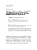
4.3.1. Service Area Information. Bangkok, the capital of
Thailand, comprises of 50 districts and is the growth pole
of the whole kingdom with total area of 1,568.74 square
kilometers. The urbanized area is about 178.82 square
kilometersoronly11.38percentsoftotalarea.Therest
of 35.32 percent and 53.30 percent are suburban area, and
rural area, respectively. Figure 7 shows the GIS-based land
use map of Bangkok. The detail demographic information
of Bangkok is found in [27, 28]. The population of Bangkok
is now more than 10 million including daily commuters. As
a megacity, Bangkok is administered by a local government
called Bangkok Metropolitan Administration (BMA). Based
on the demographic data, we define the area of BMA into
three environment, as shown in Tab le 1 1 .
4.3.2. Results of Case Study. At present, the network architec-
ture of the WiMAX in Bangkok has not yet been finalized.
Thus, we use a generic architecture of WiMAX networks,
as a typical architecture for designing the BFWA network
and apply it to all local exchanges within Bangkok. Results
Table 11: Demographic information of bangkok.
Environment
Definition
criterion
(household/km
2
)
BMA
area
(km
2
)
BMA household
density
(household/km
2
)
Urban
More than 3,000 178.52 4,312
Suburban
1,000–2,999 554.07 2,174
Rural
Less than 1,000 836.15 714
of applying the previous analysis to the case study indicate
the number of APs to fulfill both coverage and capacity. The
results, in Figure 8, show that the total number of AP is
increasing at the higher channel width. This is due to the fact
that the cell range of a higher channel throughput of high
channel width has a limit.
On the other hand, results from capacity planning
indicate that the required number of AP is opposite from
that in coverage planning. The number of AP required for
achieving traffic demand of capacity planning is decreasing
at AP configured as a higher channel width. The number of
AP increases in both area and access scenario, as depicted in
Figure 9. This is due to the fact that the higher throughput
channel has the high capacity of AP.
The compared result of BFWA network planning for
medium access scenario is shown in Figure 10. By comparing
between coverage design and capacity design, the results
show that the number of AP is varying in opposite direction.
EURASIP Journal on Wireless Communications and Networking 11
1473.51.75
Channel width (MHz)
High speed access
Medium speed access
Low speed access
0
1
2
3
4
5
6
7
8
9
×10
3
To t a l nu m b e r o f A P
(a) Coverage-based number of AP by access scenarios
1473.51.75
Channel width (MHz)
Urban area
Suburban area
Rural area
0
1
2
3
4
5
6
7
8
9
×10
2
To t a l nu m b e r o f A P
(b) Coverage-based number of AP by environment area
Figure 8: Number of AP from coverage planning.
According to (1), the number of AP required is dominated
by capacity planning.
5. Conclusion
Planning the capacity of traditional wired networks is
intuitively obvious because each active subscriber requires
fixed dedicated bandwidth and the capacity is simply the
number of subscribers that the channel can support. In a
wireless channel, the situation is considerably more complex
than wired network. Since the channel is not necessarily for
fixed size but can vary with time as environment condition
change. This is particularly relevant in adaptive modulation.
The IEEE802.16 wireless channel can be configured in a
number of different ways depending on operator prefer-
ence, regulatory constraints, and performance requirements.
Many of these configurations choice affect the channel capac-
ity, often in nonobvious ways. Accurate capacity analysis
therefore presupposes detailed specification of the number
and type of the data traffic sharing the channel. How
capacity of IEEE802.16 standard, therefore, depends on
1473.51.75
Channel width (MHz)
Urban area
Suburban area
Rural area
0
5
10
15
20
25
30
35
40
45
50
×10
3
Number of AP
(a) Number of AP needed by area
1473.51.75
Channel width (MHz)
Low speed access
Medium speed access
High speed access
0
20
40
60
80
100
120
140
160
×10
3
To t a l nu m b e r o f A P
(b) Number of AP by access scenario
Figure 9: Number of AP needed from capacity planning.
1473.51.75
Channel width (MHz)
Coverage-based design
Capacity-based design
0
2
4
6
8
10
12
14
16
×10
2
Number of AP by
coverage planning
0
10
20
30
40
50
60
70
80
90
100
×10
3
Number of AP by
capacity planning
Figure 10: Coverage design versus capacity design.
environmental conditions, configuration, and the nature of
the data traffic that is transported by the system has been
addressed. Specifically, the system capacity and throughput
of a BFWA system based on IEEE802.16 standard strongly
depends on both nonengineering factors and engineering
parameters. Among the former are frequency bandwidth
and spectrum allocation (as obtained or received from
the national regulator). Among the latter are trafficper
12 EURASIP Journal on Wireless Communications and Networking
subscriber estimations and of subscriber terminal’s adaptive
modulation choices and potential.
The research demonstrates the feasibility of designing
BFWA system with IEEE802.16 standard for connecting a
future smart home to the Internet. Through the case study,
the results from study present the feasibility of having a large
scale BFWA system in providing wireless Internet access.
The results of planning, indicated by the number of AP, of
BFWA system is dominated by capacity planning. It shows
that BFWA with IEEE802.16 standard is a capacity-limited
system.
Acknowledgment
This work was supported in part by the TOT Public Com-
pany Limited, Thailand.
References
[1] M. K. Shahid, T. Shoulian, and A. Shan, “Mobile broadband:
comparison of mobile WiMAX and cellular 3G/3G+ technolo-
gies,” Information Technology Journal, vol. 7, no. 4, pp. 570–
579, 2008.
[2] A. Yarali, S. Rahman, and B. Mbula, “WiMAX: the innovative
broadband wireless access technology,” Journal of Communi-
cations, vol. 3, no. 2, pp. 53–63, 2008.
[3] J. Zander, “Affordable multiservice wireless network-research
challenge for the next decade,” in Proceeding of the IEEE
International Symposium on Personal, Indoor Mobile Radio
Communications (PIMRC ’02), vol. 1, pp. 1–4, September
2002.
[4] P. Ritthisoonthorn, K. M. Ahmed, and D. Krairit, “Cost
effective broadband fixed wireless access: opportunity for
developing country,” in Proceedings of the 2nd International
Conference on Test beds and Research Infrastructures for the
Development of Networks and Communities (TridentCom ’06),
pp. 140–145, March 2006.
[5] K. Wanichkorn and K. Sirbu, “The role of fixed wireless access
network in the deployment of broadband service and compe-
tition in local telecommunications markets,” Department of
Engineering and Public Policy, Carnegie Mellon University4,
Pittsburgh, Pa, USA, 2003.
[6] M. Zhang and R. S. Wolff, “Crossing the digital divide: cost-
effective broadband wireless access for rural and remote areas,”
IEEE Communications Magazine, vol. 42, no. 2, pp. 99–105,
2004.
[7] J. Wang, “Will WiMAX+WLAN constitute a substitute to
3G?—a techno-economic case study,” Department of Signals,
Sensors and Systems, KTH Royal Institute of Technology,
Stockholm, Sweden, 2004.
[8] T. Smura, Digital Pictures, Plenum Press, New York, NY, USA,
2nd edition, 1995.
[9] B. Rose, “Home networks: a standards perspective,” IEEE
Communications Magazine, vol. 39, no. 12, pp. 78–85, 2001.
[10] B N. Park, W. Lee, S. Ahn, and S. Ahn, “QoS-driven wireless
broadband home networking based on multihop wireless
mesh networks,” IEEE Transactions on Consumer Electronics,
vol. 52, no. 4, pp. 1220–1228, 2006.
[11] S. Raman and M. Pipatanasomporn, “Alternate technologies
for telecommunications and Internet access: remote loca-
tions,” in Proceeding of the 3rd Mediterranean Conference and
Exhibition on Power Generation, Transmission, Distribution
and Energy Conversion, Athens, Greece, November 2002.
[12] B. Lannoo, S. Verbrugge, J. Van Ooteghem, et al., “Business
scenarios for a WiMAX deployment in belgium,” in Proceeding
of the IEEE Mobile WiMAX Symposium Conference, pp. 132–
137, March 2007.
[13] L. Bai, Analysis of the market for WiMAX service, M.S. thesis,
Center for information and communication technologies,
Technology University of Denmark, Lyngby, Denmark, May
2007.
[14] />[15] A. Ghosh, D. R. Wolter, J. G. Andrews, and R. Chen, “Broad-
band wireless access with WiMax/802.16: current performance
benchmarks, and future potential,” IEEE Communications
Magazine, vol. 43, no. 2, pp. 129–136, 2005.
[16] S. Redana and M. Lott, “Performance analysis of IEEE 802.16a
in mesh operation mode,” in Proceeding of the IST Summit,
June 2004.
[17] C. Eklund, R. B. Marks, K. L. Stanwood, and S. Wang, “IEEE
standard 802.16: a technical overview of the wirelessMAN
TM
air interface for broadband wireless access,” IEEE Communi-
cations Magazine, vol. 40, no. 6, pp. 97–107, 2002.
[18] D. Gesbert, L. Haumonte, H. Bolcskei, R. Krishnamoorthy,
and A. J. Paulraj, “Technologies and performance for non-
line-of-sight broadband wirless access networks,” IEEE Com-
munications Magazine, vol. 40, no. 4, pp. 86–95, 2002.
[19] I. Koffman and V. Roman, “Broadband wireless access
solutions based on OFDM access in IEEE 802.16,” IEEE
Communications Magazine, vol. 40, no. 4, pp. 96–103, 2002.
[20] K. Johansson, A. Furusk
¨
ar, P. Karlsson, and J. Zander, “Rela-
tion between base station characteristics and cost structure
in cellular systems,” in Proceeding of the IEEE International
Symposium on Personal, Indoor Mobile Radio Communications
(PIMRC ’04), vol. 4, pp. 2627–2631, September 2004.
[21] H. R. Anderson, Fixed Broadband Wireless System Design,John
Wiley & Sons, 2003.
[22] G. Plitsis, “Coverage prediction of new elements of systems
beyond 3G: the IEEE 802.16 system as a case study,” in
Proceeding of the IEEE Vehicular Technology Conference (VTC
’03), vol. 4, pp. 2292–2296, October 2003.
[23] V. S. Abhayawardhana, I. J. Wassellt, D. Crosby, M. P. Sellars,
and M. G. Brown, “Comparison of empirical propagation path
loss models for fixed wireless access systems,” in Proceeding of
the IEEE Vehicular Technology Conference (VTC ’05), vol. 1, no.
1, pp. 73–77, May 2005.
[24] M. J. Nawrocki, M. Dohler, and A. Hamid Aghvami, Under-
standing UMTS Radio Network, John Wiley & Sons, 2006.
[25] P. Ritthisoonthorn, “Telecommunication Program,” Internal
Project Report, Asian Institute of Technology, November 2007.
[26] P. Ritthisoonthorn, K. M. Ahmed, and D. Krairit, “User
behavior and Internet access network performance in a
broadband environment,” in Proceeding of the International
MultiConference of Engineers and Computer Scientist (IMECS
’07), March 2007.
[27] The Bangkok Metropolitan Administration, “Bangkok over-
view,” />[28] “The Bangkok GIS information,” gkokgis.
com/.