Advances in Optical and Photonic Devices 2011 Part 13 potx
Bạn đang xem bản rút gọn của tài liệu. Xem và tải ngay bản đầy đủ của tài liệu tại đây (1.85 MB, 25 trang )
Optical Mode Properties of 2-D Deformed Microcavities
289
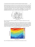
Fig. 11. (a) The topology of energy surface near an EP. (b) Möbius strip made by the
difference of eigenvalues of interacting two modes.
In a stadium-shaped microcavity, the exceptional point has been found numerically near an
ARC (Lee, S Y. et al., 2008b) in a parameter space spanned by a deformation and refractive
index. Recently, ARC and RC in microcavity have been experimentally observed in a
deformed microcavity made by liquid jet, where some discrete internal parameter, instead
of the refractive index, is used and it is expected that the EP would be identified by
observing the transition ARC to RC (Lee , S B. et al., 2009).
7. Summary
In this chapter, properties of optical modes in deformed dielectric microcavities have been
reviewed. Although the ray dynamics in deformed cavity is complicated, through the PSOS
one can easily identify the complexity of ray dynamics. The modified PSOS incorporating
openness character of dielectric cavity can be characterized by the steady probability
distribution (SPD) for fully chaotic case. This distribution reveals combination of unstable-
manifold structure and openness character, and it plays a role of classical skeleton for
understanding Husimi functions of optical modes supported by deformed microcavities.
The directional emission from a strongly deformed microcavity can be well explained by the
SPD. Influence of openness changes scarred optical modes to have opposite angular shift of
scarred patterns depending on the way of wave circulation, and make it possible to form
quasiscarred optical modes without underlying unstable periodic orbit. And the dielectric
microcavity can be regarded as an example of non-Hermitian system with complex
eigenvalues. The exceptional point (EP), degeneracy point in non-Hermitian systems, can be
found in deformed microcavities.
Although much attention has been paid on the microcavity in the past decades and new
understandings on optical modes have been achieved, there remain still many challenges.
Multi-dimensional tunnelling appears in slightly deformed microcavities. However, there is
no quantitative semiclassical theory to treat this tunnelling. Only a perturbation theory, for
near integrable microcavity, explains tunnelling emissions (Creagh, 2007). Non-Hermitian
properties of optical modes are also important due to their generality applicable to other
open quantum systems. The Petermann excess noise factor, a measure of non-orthogonality
Advances in Optical and Photonic Devices
290
of eigenstates, is known to diverge at the EP, but its physical implications on the
spontaneous emission rate and laser line width are not obvious so far. (Cheng, 2006; Lee, S
Y. et al, 2008b; Schomerus, 2009)
8. Acknowledgements
This work was supported by BK21 program and KRF Grant (2008-314-C00144).
9. References
Altmann, E. G. (2009). Emission from dielectric cavities in terms of invariant sets of the
chaotic ray dynamics, Phys. Rev. A, Vol. 79, No. 1, (Jan. 2009) 013830, ISSN 1050-
2947.
Ben-messaoud, T. & Zyss, J. (2005). Unidirectional laser emission from polymer-based spiral
microdisks. Appl. Phys. Lett., Vol. 86, No. 24, (Jun. 2005) 241110, ISSN 0003-6951.
Cheng, Y J. (2006). Spontaneous emission of an atom in a cavity with nonorthogonal
eigenmodes. Phys. Rev. Lett., Vol. 97, No. 9, (Aug. 2006) 093601, ISSN 0031-9007.
Chern, G. D.; Tureci, H. E.; Stone, A. D.; Chang, R. K.; Kneissl, M. & Johnson, N. M. (2003).
Unidirectional lasing from InGaN multiple-quantum-well spiral-shaped
micropillars. Appl. Phys. Lett., Vol. 83, No. 9, (Sep. 2003) 1710-1712, ISSN 0003-6951.
Creagh, S. C. (2007). Directional emission from weakly eccentric resonator. Phys. Rev. Lett.,
Vol. 98, No. 15, (Apr. 2007) 153901, ISSN 0031-9007.
Dubertrand, R.; Bogomolny, E.; Djellali, N.; Lebental, M. & Schmit, C. (2008). Circular
dielectric cavity and its deformations. Phys. Rev. A, Vol. 77, No. 1, (Jan. 2008)
013804, ISSN 1050-2947.
Harayama, T.; Davis, P. & Ikeda, K. S. (2003) Stable oscillations of a spatially chaotic wave
function in a microstadium laser. Phys. Rev. Lett., Vol. 90, No. 6, (Feb. 2003) 063901,
ISSN 0031-9007.
Heller, E. J. (1984). Bound-state eigenfunctions of classically chaotic Hamiltonian system:
scars of periodic orbits. Phys. Rev. Lett., Vol. 53, No. 16, (Oct. 1984) 1515-1518, ISSN
0031-9007.
Hentschel, M.; Schomerus, H. & Schubert, R. (2003). Husimi functions at dielectric
interfaces: Inside-outside duality for optical systems and beyond. Europhys. Lett.,
Vol. 62, No. 5, (Jun. 2003) 626-642, ISSN 0295-5075.
Kim, C M.; Cho, J.; Lee, J.; Rim, S.; Lee, S. H.; Oh, K. R. & Kim, J. H. (2008). Continuous
wave operation of a spiral-shaped microcavity laser. Appl. Phys. Lett., Vol. 92, No.
13, (Apr. 2008) 131110, ISSN 0003-6951.
Kim, C M.; Lee, S H.; Oh, K R. & Kim, j. H. (2009). Experimental verification of
quasiscarred resonance mode. Appl. Phys. Lett., Vol. 94, No. 23, (Jun. 2009) 231120,
ISSN 0003-6951.
Kwon, T Y.; Lee, S Y.; Kurdoglyan M. S.; Rim S.; Kim, C M. & Park Y J. (2006). Lasing
modes in a spiral-shaped dielectric microcavity. Opt. Lett., Vo. 31, No. 9, (May 2006)
1250-1252, ISSN 0146-9592.
Kurdoglyan, M. S.; Lee, S Y.; Rim, S. & Kim, C M. (2004). Unidirectional lasing from a
microcavity with a rounded isosceles triangle shape. Opt. Lett., Vol. 29, No. 23,
(Dec. 2004) 2758-2760, ISSN 0146-9592.
Optical Mode Properties of 2-D Deformed Microcavities
291
Lee, S B.; Lee, J H.; Chang, J S.; Moon, H J.; Kim, S. W. & An, K. (2002). Observation of
scarred modes in asymmetrically deformed microcylinder lasers. Phys. Rev. Lett.,
Vol. 88, No. 3, (Jan. 2002) 033903, ISSN 0031-9007.
Lee, S B.; Yang, J.; Moon, S.; Lee, J H.; An, K.; Shim, J B.; Lee, H W. & Kim, S. W. (2007).
universal output directionality of single modes in a deformed microcavity. Phys.
Rev. A, Vol. 75, No. 1, (Jan. 2007) 011802(R), ISSN 1050-2947.
Lee, S B.; Yang, J.; Moon, S.; Lee, S Y.; Shim, J B.; Kim, S. W.; Lee, J H. & An, K. (2009).
Quasieigenstate evolution in open chaotic billiards. Phys. Rev. A, Vol. 80, No. 1, (Jul.
2009) 011802(R), ISSN 1050-2947.
Lee, S Y.; Rim, S.; Ryu, J W.; Kwon, T Y.; Choi, M. & Kim, C M. (2004). Quasiscarred
resonances in a spiral-shaped microcavity. Phys. Rev. Lett., Vol. 93, No. 16, (Oct.
2004) 164102, ISSN 0031-9007.
Lee, S Y.; Ryu, J W.; Kwon, T Y.; Rim, S. & Kim, C M. (2005). Scarred resonances and
steady probability distribution in a chaotic microcavity. Phys. Rev. A, Vol. 72, No. 6,
(Dec. 2005) 061801(R), ISSN 1050-2947.
Lee, S Y.; Rim, S.; Ryu, J W.; Kwon, T Y.; Choi, M. & Kim, C M. (2008a). Ray and wave
dynamical properties of a spiral-shaped dielectric microcavity. J. Phys. A: Math.
Theor., Vol. 41, No. 27, (Jul. 2008) 275102, ISSN 1751-8113.
Lee, S Y.; Ryu, J W.; Shim, J B.; Lee, S. W. & An, K. (2008b). Divergent Petermann factor of
interacting resonances in a stadium-shaped microcavity. Phys. Rev. A, Vol. 78, No.
1, (Jul. 2008) 015805, ISSN 1050-2947.
Lee, J.; Rim, S.; Cho, J. & Kim, C M. (2008). Resonances near the classical separatrix of a
weakly deformed circular microcavity. Phys. Rev. Lett., Vol. 101, No. 6, (Aug. 2008)
064101, ISSN 0031-9007.
Mailybaev, A. A.; Kirillov, O. N. & Seyranian, A. P. (2005), Geometrical phase around
exceptional points. Phys. Rev. A, Vol. 72, No. 1, (Jul. 205) 014104, ISSN 1050-2947.
McCall, S. L.; Levi, A. F. J.; Slusher, R. E.; Pearton, S. J. & Logan, R. A. (1992). Whispering-
gallery mode microdisk lasers. App. Phys. Lett., Vol. 60, No. 3, (Jan. 1992) 289-291,
ISSN 0003-6951.
Nöckel, J. U. & Stone, D. (1997). Ray and wave chaos in asymmetric resonant optical cavities.
Nature, Vol. 385, No. 6611, (Jan. 1997) 45-47, ISSN 0028-0836.
Podolskiy, V. A. & Narimanov, E. E. (2005). Chaos-assisted tunneling in dielectric
microcavities. Opt. Lett., Vol. 30, No. 5, (Mar. 2005) 474-476, ISSN 0146-9592.
Reichl, L. E. (1992). The transition to chaos, Springer-Verlag, ISBN 3-540-97753-8, New York.
Rex, N. B.; Tureci, H. E.; Schwefel, H. G. L.; Chang, R. K. & Stone, A. D. (2002). Fresnel
filtering in lasing emission from scarred modes of wave-chaotic optical resonators.
Phys. Rev. Lett., Vol. 88, No. 9, (Feb. 2002) 094102, ISSN 0031-9007.
Ryu, J W.; Lee, S Y. & Kim S. W. (2009). Coupled nonidentical microdisks: Avoided
crossing of energy levels and unidirectional far-field emission. Phys. Rev. A, Vol. 79,
No. 5, (May 2009) 053858, ISSN 1050-2947.
Shim, J B.; Lee, S B.; Kim, S. W.; Lee, S Y.; Yang, J.; Moon, S.; Lee, J H. & An, K. (2008).
Uncertainty-limited turnstile transport in deformed microcavities. Phys. Rev. Lett.,
Vol. 100, No. 17, (May 2008) 174102, ISSN 0031-9007.
Schomerus, H. (2009). Excess quantum noise due to mode nonorthogonality in dielectric
microresonators. Phys. Rev. A, Vol. 79, No. 6, (Jun. 2009) 061801(R), ISSN 1050-2947.
Advances in Optical and Photonic Devices
292
Schwefel, H.; Rex, N.; Tureci, H.; Chang, R. K.; Stone, A. D.; Ben-Messaoud, T. & Zyss, J.
(2004). Dramatic shape sensitivity of directional emission patterns from similarly
deformed cylindrical polymer laser. J. Opt. Soc. Am. B, Vol. 21, No. 5, (May 2004)
923-934, ISSN 0740-3224.
Shang, L.; Liu, L. & Xu, L. (2008). Highly collimated laser emission from a peanut-shaped
microcavity. Appl. Phys. Lett., Vol. 92, No. 7, (Feb. 2008) 071111, ISSN 0003-6951.
Shinohara S. & Harayama, T. (2007). Signature of ray chaos in quasibound wave functions
for a stadium-shaped dielectric cavity. Phys. Rev. E, Vol. 75, No. 3, (Mar. 2007)
036216, ISSN 1539-3755.
Takami, T. (1992). Semiclassical interpretation of avoided crossing for classically
nonintegrable system. Phys. Rev. Lett., Vol. 68, No. 23, (Jun. 1992) 3371-3374, ISSN
0031-9007.
Tulek, A. & Vardeny, Z. V. (2007). Unidirectional laser emission from p-conjugated polymer
microcavities with broken symmetry. Appl. Phys. Lett.,Vol. 90, No. 16, (Apr. 2007)
161106, ISSN 0003-6951.
Unterhinninghofen J.; Wiersig, J. & Hentschel M. (2008). Goos-Hänchen shift and
localizatioin of optical modes in deformed microcavities. Phys. Rev. E, Vol. 78, No.
1, (Jul. 2008) 016201, ISSN 1539-3755.
Vahala, K. (2003). Optical microcavities, Nature, Vol. 424, No. 6950, 839-846, ISSN 0028-0836.
Wiersig J. (2003). Boundary element method for resonances in dielectric microcavities. J. Opt.
A: Pure Appl. Opt., Vol. 5, No. 1, (Jan. 2003) 53-60, ISSN 1464-4258.
Wiersig J. (2006). Formation of long-lived, scarlike modes near avoided resonance crossings
in optical microcavities. Phys. Rev. Lett., Vol. 97, No. 25, (Dec. 2006) 253901, ISSN
0031-9007.
Wiersig J. & Hentschel M. (2006). Unidirectional light emission from high-Q modes in
optical microcavities. Phys. Rev. A, Vol. 73, No. 1, (Jan. 2006) 013802(R) (2006), ISSN
1050-2947.
Wiersig J. & Hentschel M. (2008). Combining directional light output and ultralow loss in
deformed microdisks. Phys. Rev. Lett., Vol. 100, No. 3, (Jan. 2008) 033901, ISSN 0031-
9007.
16
Practical Continuous-Wave Intracavity
Optical Parametric Oscillators
Dr David J M Stothard
University of St. Andrews
United Kingdom
1. Introduction
The mid-infrared spectroscopic region (~1.5-5μm) is one of ever increasing importance.
Many hazardous, contraband or otherwise important molecules and compounds exhibit
their peak rotational and vibrational absorption features over this wavelength range and so
can be readily detected and identified through the use of spectroscopic techniques. There is
an urgent requirement, therefore, for high spectral purity, compact and wavelength-flexible
optical sources operating over this range. Laser based spectrometers operating at visible or
near-infrared wavelengths offer a combination of unprecedented resolution and ease of use
due to their extremely high spectral brightness and tunability. Mid-infrared laser-based
spectroscopy is, however, far less developed (even though this spectral range is arguably of
more scientific importance) due to a severe lack of suitable continuous-wave (cw), broadly
tunable laser sources. Whilst this area has attracted intense research interest over the past
decade, current state-of-the-art mid-infrared laser systems are still not poised to address this
shortfall. Quantum-cascade, difference-frequency mixing techniques and lead-salt diodes
produce very low output power, limited tunability, poor spatial mode quality, require
liquid cryogens, or a combination of these.
Fig. 1. The generation of long wavelength light through parametric frequency down-
conversion. Here, ν
p
=ν
s
+ν
i
.
The use of nonlinear optical techniques to convert the output of laser systems operating at
too short a wavelength, but otherwise exhibiting meritorious characteristics (e.g. high
efficiency, robust design, etc) to the low frequency, mid-IR band of interest has received
considerable interest since the invention of the laser in the early 1960s. Such nonlinear
devices are called optical parametric oscillators (OPOs) and they operate by dividing the
energy of an incoming, high energy pump photon into two lower energy photons (denoted
the signal and idler); the energy (and hence, frequency) of which add up to that of the pump
Advances in Optical and Photonic Devices
294
(see Fig. 1). One of the simplest incarnations of this device is the externally-pumped, or
extra-cavity, singly-resonant OPO (ECOPO) - (see Fig. 2(a)). Here, a nonlinear optical crystal is
placed within an optical cavity exhibiting high finesse at one of the down-converted waves
(most usually, the signal wave). Once pumped hard enough, the parametric gain overcomes
the round-trip loss experienced by the resonant wave and the OPO reaches threshold:
down-conversion from the incident pumping wave to signal and idler begins. Crucially, as
the parametric process is not limited to a particular electronic or vibrational transition (as in
the case of a laser), the tuning range of the down converted signal and idler waves are
limited only by the transparency of the nonlinear dielectric material in which they are
generated. Hence it is possible to realise devices which exhibit very broad tunability in the
down-converted signal and idler waves even if the pumping laser is not itself tunable
(although pump-laser tunability does enable an additional tuning mechanism).
Fig. 2. Externally-pumped (a), and intracavity (b) optical parametric oscillators (ECOPO and
ICOPO). Note that in both of these geometries, the optical cavity in which the nonlinear
crystal resides is resonant at only one of the down-conveted waves (i.e. either signal or idler).
It is the large offset pumping power needed before downconversion begins (the threshold
pumping power) which is the main objection to the widespread implementation of the
ECOPO. Before the advent of long interaction length periodically-polled nonlinear crystals
exhibiting comparatively large nonlinearity-interaction length products, threshold pumping
powers were on the order of many tens of watts – therefore precluding their use with all but
the most powerful cw pump lasers. When one takes into account the primary pumping
power required to excite the pumping laser gain medium then the overall efficiency picture
of these devices looks even bleaker. This has changed with the introduction of the
aforementioned periodically-poled nonlinear materials, most notably the now-ubiquitous
periodically-polled LiNbO
3
(PPLN) crystal. This brought threshold pumping powers down
to the 3-5W level, i.e. within the reach of moderately powered cw laser systems. Overall
“wall-plug” efficiency is however still very poor, though, unless ECOPOs are operated well
above (~2-3x) threshold (more of this on section 2.1). The highly efficient production of
Practical Continuous-Wave Intracavity Optical Parametric Oscillators
295
multiple-watt output in the down-converted signal and idler fields is therefore perfectly
possible (and indeed has been amply demonstrated (Bosenberg, Drobshoff et al. 1996)) in
the ECOPO geometry but very poor efficiency results when the output is in the 10s-100s mW
region (i.e. the device is operated closer to threshold). This is problematic as many (if not
most) of the potential applications of a broadly tunable mid-IR source only require moderate
power levels. In addition to this, for many industrial, medical, forensic and field uses, high
efficiency, highly compact devices (i.e. battery powered, air-cooled) are a must.
Fig. 3. A well-engineered, all solid-state miniaturised cw-ICOPO. This device consumes just
~10W electrical power, can deliver >500mW in the down-converted optical fields and requires
no forced cooling. The function of the various components is discussed later in the text.
An elegant solution to this problem comes through taking advantage of the very high
circulating field found within the (high-finesse) cavity of a laser. If one replaces the lasers’
output coupling mirror with a high reflector, very high (10’s W) circulating fields can result
even when pumped at low (100’s mW) levels. Placing the OPO inside the laser cavity (see
Fig. 2(b)) then gives the parametric process access to this high field and the OPO comes to
threshold at very much lower primary pumping powers than is the case with the ECOPO,
thus obviating the high primary pumping power threshold requirements associated with
that geometry. This, the intracavity optical parametric oscillator (ICOPO) enables the realisation
of extremely compact, highly efficient devices which can exhibit high output powers in the
down converted waves (100’s mW) when pumped with only very modest (1’s W) primary
(i.e. diode-laser) pumping sources. An important consequence of the unprecedented down-
conversion efficiency afforded by the intracavity approach, coupled with the robust
operating nature of the singly-resonant design, is the possibility of realising battery / field
operable systems as the need for large frame pumping lasers, forced water cooling and high
cost is eliminated. A photograph of such a system is shown in Fig. 3. Here, for just 3W of
primary pump power from the integrated diode laser pump module, 300mW and 150mW of
Advances in Optical and Photonic Devices
296
broadly tunable signal and idler power are delivered. Because of the very high efficiency
exhibited by the ICOPO, no forced air or water cooling is required. The device consumed
<10W electrical power, making it ideal for battery power, portable or remote operation.
From a power and efficiency point of view, then, the cw-ICOPO represents an excellent
solution to the problem of inadequate spectroscopic laser-source coverage over the mid-IR
range. Unfortunately, there is a particular problem associated with the intracavity approach
which has to date severely hampered its widespread implementation. The practical
application of very narrow linewidth (sub MHz), diode pumped ICOPOs requires continuous
wave output and therein lies a serious limitation inherent in the underpinning physics of the
ICOPO. This is due to the impact of the OPO upon the transient dynamics of the Neodymium-
based pump lasers in which to date they have been operated. Clearly, maintaining a diode
pumped, all solid-state parent laser is highly desirable and hence the majority of ICOPO
research has been predicated upon the use of Neodymium (Nd) based laser gain media. Whilst
exhibiting many excellent characteristics ideally suited to this technology, their long upper
state lifetime (compared to the decay time of the laser and signal waves in their respective
cavities) leads to unpredictable and prolonged bursts of relaxation oscillations when used in
consort with the intracavity technique. Such behaviour has an unacceptable impact on the
frequency and amplitude stability of the down-converted waves and has to date precluded the
Nd-based CW ICOPO from having lived up to its considerable potential.
In this chapter we will explore the design criteria for the realisation of practical intracavity
cw-OPO systems, with a particular emphasis on overcoming their susceptibility to the
spontaneous onset of relaxation oscillations. We shall begin with a comparison between the
operating characteristics of cw intracavity OPOs and their externally-pumped counterparts
(without becoming bogged down in a turgid foray into nonlinear optical theory (Oshman &
Harris 1968)), and the design rules which must be fulfilled in order to realise optimal
operation in the intracavity regime. These rules will be applied and tested by then
considering the design and realisation of a real-life system previously reported in the
literature; the steps taken in order to maximise the chances of successful operation of the
device will be reviewed. The discussion will then move on to the vexing problem of
relaxation oscillations which occur in the intracavity context; this will be investigated with
the aid of a simple numerical model showing how and why they occur. The remainder of
the chapter will then describe two examples of state-of-the-art diode laser pumped, cw-
ICOPOs which are designed to obviate the problem of relaxation oscillations without losing
any of the significant advantages which the intracavity technique confers.
2. The power characteristics of optical parametric oscillators
Much has been written on the principles underpinning the operation of OPOs and we shall
avoid repetition here. For a theoretical and analytical thorough discussion of the physical
processes underpinning these devices the reader should refer to (Ebrahimzadeh & Dunn
1998). In this section we shall describe the different operating regimes of both intra- and
extra- cavity OPOs and examine those best suited to each geometry. Finally, we shall briefly
discuss a strategy for operating the ICOPO under optimal efficiency conditions.
2.1 Power characteristics and the advantage of the intracavity technique
It is a common misconception that the ICOPO is somehow fundamentally superior to the
ECOPO in terms of conversion efficiency, due to its much lower external threshold pump
Practical Continuous-Wave Intracavity Optical Parametric Oscillators
297
power requirements. Whilst this is certainly true at lower powers, where the ICOPO is
capable of efficient output when the ECOPO would not even be able to achieve threshold, at
higher pump powers we shall see that the ECOPO is also capable of exhibiting excellent
conversion efficiency. The crucial disadvantage of the ECOPO is its large offset threshold
pumping power requirement.
Fig. 4. Down-conversion characteristics of IC- and EC-OPOs
Even with high quality, modern nonlinear crystals exhibiting a high nonlinearity and
interaction length, the finite cavity round trip loss for the down converted wave sets the
minimum attainable ECOPO threshold in the region of ~2-5W, which would require at least
5-10W of primary optical diode pump power simply to reach threshold. However, once above
threshold the down conversion efficiency (that is, the fraction of incident pump power
down converted to longer wavelengths) rapidly increases to the point at which 100% down
conversion efficiency is achieved once the ECOPO is pumped ~2.5 times above its threshold
level (Ebrahimzadeh & Dunn 1998). A good example of this is (Bosenberg, Drobshoff et al.
1996) where ~93% of the incident 1μm pumping power was down converted into signal and
idler power. ECOPOs have enjoyed something of a revival in recent years due to the
Advances in Optical and Photonic Devices
298
availability of high power, high spatial and longitudinal mode quality fibre lasers and the
drop in cost of their associated diode laser pumping modules. The requirement to operate
these devices 2-3 times threshold, and the limitations in nonlinear crystal interaction length
/ nonlinearity and finite signal round-trip loss, still results in the requirement for many 10’s
W electrical power required in order to operate these devices efficiently. Such a requirement
precludes the realisation of the ECOPO in compact, low power designs.
The various operating regimes in which the devices can be operated are shown graphically
in Fig. 4, where the output power characteristics of the parent pump laser, an ECOPO and
an ICOPO are contrasted. In this model, a typical parent laser is assumed (i.e. Nd:YVO
4
,
pumped by an 808nm laser, ~2% round trip parasitic loss) and the linear loss effects of the
intracavity OPO components is ignored. A note on nomenclature: “down-conversion
efficiency” and “down-converted power” refer to the total power converted through the
parametric process, i.e. both idler and signal. In general, only the longer wave idler is of
interest and none of the signal is usefully extracted (although this need not be so – output
coupling of the signal field is perfectly possible if this wavelength is also required).
Therefore, a second axis has been added in the figure to indicate the total idler power
obtained from the device, taking into account the quantum defect between the diode pump
and generated idler field wavelengths.
So that the performance of each pumping geometry can be better compared, the threshold
condition of the ICOPO and ECOPO in the model have been tailored such that maximum
efficiency in either case occurs at the same pumping power (in this example, at about
11.5W). In reality this means artificially increasing the threshold of the ICOPO (by
modelling the pump and signal field with only a very weak focus in the nonlinear material);
real-world ICOPOs exhibit OPO threshold at far lower pumping powers than shown here –
as little as a few hundred mW (Stothard, Ebrahimzadeh et al. 1998). We can see that Fig. 4
has been separated into 6 ‘zones’ of operation. The first and second are merely below and
above laser threshold, respectively. The ICOPO comes to threshold at the beginning of zone
III, still well before threshold occurs in the ECOPO. In zone IV, ECOPO operation is
achieved but the down converted power is still significantly less than in the case of the
ICOPO. Clearly, if the available pump power were limited to the range ~2.5-8W then the
ICOPO is obviously the superior choice in terms of the amount of mid-infrared light
generated. As the down-conversion efficiencies in either case become optimised (i.e. near
unity), the total down- converted power is comparable in each case (zone V) and there is
little to differentiate between the two devices in terms of performance. In order to optimise
for maximum overall efficiency, both devices would be operated in this zone. As the pump
power is increased beyond the optimum operating condition (zone VI), the efficiency in each
case drops (markedly so in the case of the ECOPO). Here, back conversion of the signal and
idler takes place. In practice, one would not operate either device in this zone; in order to
obtain very high output powers and maintain optimal efficiency the threshold of each OPO
would be increased such that optimal down conversion (zone IV) occurs at the required
operating point. The crucial advantage of the ICOPO over the ECOPO is that in a practical
device, zone V can be achieved at very much lower primary pumping levels, whereby a
combination of very high efficiency and moderate down-converted output power is possible.
In the ECOPO, high efficiency is only achievable at ~2.5x threshold. As this threshold is
locked at relatively high powers by the finite parametric gain / signal wave loss product
(~2-5W of incident pumping power), high efficiency only occurs when very high powers are
being obtained. For clarity, we summarise these operating regimes in tabular form.
Practical Continuous-Wave Intracavity Optical Parametric Oscillators
299
Zone Operating Regime Notes
I
Laser below threshold
II
Laser above threshold
III
ICOPO above threshold
IV
ECOPO above threshold
If diode pump power is limited then ICOPO
performance clearly superior over these zones
V
Down conversion
approaches 100%
Little to differentiate between devices in terms of
down-conversion performance
VI
Over pumping Would never operate either device here in practice
Table 1. Summary of the operating ’zones’ depicted in Fig. 4
In the above treatment, the linear loss of the intracavity OPO components placed within the
parent pump laser is ignored. In the case of the ECOPO, the pump is only used on a single
pass and so linear loss effects, to a first approximation, have little impact upon performance.
However, placing lossy components within a laser cavity has obvious consequences in terms
of laser performance. With reference to Fig. 2(b) we see that the two additional components
which the laser cavity must tolerate are the dichroic beamsplitter and nonlinear optical
crystal. Clearly, these components must be antireflection coated in order to minimise loss at
the pump wavelength. It is particularly important to secure the finest coatings available
upon the nonlinear crystal and inner surface of the beamsplitter as these need to be specified
at three separate wavelengths. However, coating techniques have now matured to the point
at which such advanced coatings are generally obtainable, particularly in devices which do
not require broad tuning of the OPO (and, hence, broad-band AR/HR coatings). For a well
established nonlinear crystal such as PPKTP or PPLN, absorption at the pump wavelength is
negligible and so the additional round trip loss of the ICOPO components can be as low as
~3-5% at the pumping wavelength. Significant crystal-induced loss is only encountered, and
is therefore problematic, when the intracavity technique is used in conjunction with lossy
nonlinear materials, such as ZGP pumped at ~2μm. In this case, care has to be taken that the
round trip loss of the laser cavity accommodating such lossy components does not impact
too heavily on the attainable circulating field and, hence, obviate the advantage that the
intracavity technique confers. The use of such crystals is beyond the scope of this chapter.
2.2 ICOPO efficiency optimisation
Unlike the case of a laser, minimizing the point at which the ICOPO comes to threshold (in
terms of the primary pump power from the laser-diode) does not necessarily bring about the
highest output (or efficiency) at the maximum available pump power. This is because the
nonlinear parametric process acts as the output coupler for the laser, and so for a given
pumping power one requires that the OPO operates in such a way that it behaves as an optimal
output coupler for the pump cavity (i.e. is operating in zone V (Fig. 4) for a given primary
pumping power). Therefore, the threshold level of the OPO, in terms of external pumping
power, is a function of both laser threshold and the external pumping power at which the
device is to be optimised. If the OPO comes to threshold too quickly, then at the maximum
available primary pumping power the laser will be over coupled, hence reducing the down-
converted power obtained. For a particular value of laser threshold and maximum available
primary pumping power, optimum down-conversion efficiency occurs when the condition
Advances in Optical and Photonic Devices
300
in
L
th
OPO
th
PPP ⋅= (1)
is met (Colville, Dunn et al. 1997), where P
th
L
and P
th
OPO
are the primary pump powers at
which the laser and OPO, respectively, reach threshold, and P
in
is the primary pumping
power at which the device is to be optimised. When operated in this regime, the ICOPO acts
as an optimum output coupler to the parent pump laser and maximum conversion of
primary pump to down-converted power is achieved (this power being equal to that
extractable from the pump laser under optimal output-coupling conditions with the OPO
components accommodated within the pump cavity but with down-conversion
suppressed).
Fig. 5. (a) Linear output power of OPO once above threshold and (b) clamping effect of the
ICOPO upon the circulating field (Turnbull, Dunn et al. 1998)
Whilst a very low value of P
th
OPO
is highly desirable when the available primary pumping
power is limited, reduced down-conversion powers are experienced when higher power
pump sources are used as the system is operated too many times above threshold (because
of the aforementioned over coupling of the pump field). Due to the high pumping fields
available when using the intracavity technique, coupled with the low parametric thresholds
enabled by long interaction-length, high-nonlinearity periodically-poled crystals, a choice
can therefore be made when optimising the performance of the device either for maximum
down-converted power or minimising parametric threshold in terms of primary pump
power. Both of these cases are considered in a practical system later on in section 5.2.
Once above threshold, the parametric oscillator acts like an optical zener diode and ‘clamps’
the circulating field at the OPO threshold value, as shown in Fig. 5(b). Increased pumping
power is then transferred from the laser gain medium population inversion, through the
circulating field into increased power in the signal and idler waves, which grow linearly.
When characterising the performance of an ICOPO, it is often well worth measuring the
Practical Continuous-Wave Intracavity Optical Parametric Oscillators
301
quality of the pump-field clamping above OPO threshold as the primary diode pump power
is increased. Good clamping is indicative of a well designed pump and signal cavity which
is either free of (or robust in the presence of) any dynamic thermal effects which may be
present within the laser gain medium and nonlinear optical crystals. Significant thermal lens
effects manifest themselves in poor clamping of the pump field and a non-linear
relationship between primary pumping and down-converted power. We shall see examples
in the following section of how to calculate the circulating field required to bring the OPO to
threshold, and experimental observations of the pump-field clamping effect.
Let us now take these simple design rules and see how they are applied when planning,
constructing and characterising a system on the optical bench.
3. Designing a cw-ICOPO
In this section we shall take a specific example of a previously demonstrated ICOPO system
reported in the literature (Stothard, Ebrahimzadeh et al. 1998) and walk through the process
of realising such a device, ensuring that the first-time experimentalist will maximise his or
her chances of success – by which we primarily mean at least getting the OPO above
threshold. Here we will assume the experimenter has access to readily available pumping
sources, Nd laser gain media and nonlinear crystals.
Fig. 6. A simple cw PPLN- Nd:YVO
4
ICOPO (Stothard, Ebrahimzadeh et al. 1998)
Our requirement is that the device, once constructed, will operate comfortably above
threshold, delivering 10’s mW of tunable power in the down-converted waves. Steps to
circumvent the onset of relaxation oscillations will not be addressed in this discussion; here
we will restrict ourselves to simply realising a low threshold, high efficiency device. In
particular, we will consider the practical design choices which were taken in order to realise
the first ICOPO based upon Nd as reported in (Stothard, Ebrahimzadeh et al. 1998), and use
the physical parameters as used in that case. A schematic of that device is shown in Fig. 6.
The system was pumped by a c-packaged, temperature stabilised diode laser capable of
delivering just 1W of optical power into the rear face of a 1% doped Nd:YVO
4
laser crystal.
The laser cavity was defined by a highly reflective (at 1.064μm) coatings applied directly to
the outer-most facet of the laser gain crystal and mirror M2. All of the components within
the cavity were anti-reflection coated, such that the round trip loss experienced by the pump
field was ~3%. Mirror M2 was also coated to be highly reflecting at the signal wavelength,
Advances in Optical and Photonic Devices
302
as was M3 and the dichroic beamsplitter BS, thus defining the signal cavity. Due to the
limited diode pump power available (only 1W), a crystal exhibiting a high nonlinearity /
length product (more on this in the following section) was required in order to minimise
parametric threshold, and so a 50mm long PPLN crystal was procured. This was placed
within an oven to avoid the effects of photorefractive damage.
Fig. 7. Stability simulation of the pump cavity. Note that the beamsplitter has no focal power
and is therefore omitted. Its optical length is encorporated into distance D2.
The cavity was modelled and its pump mode diameter, as a function of cavity position, is
shown in Fig. 7. It is important that the cavity remain stable over a wide range (~50mm →
∞) of thermally-induced (by the diode pump) radius of curvatures modelled in mirror M1.
Note the somewhat large distance D3 between the PPLN crystal and M2; this was set by the
mirror substrate radius of curvature available at the time of the experiment (200mm). Such a
long distance and the use of a relatively weak focal-length mirror results in a somewhat
“loose“ cavity, more susceptable to the effects of thermally-induced lensing prevalent in the
PPLN crystal. A better solution is to use a substantially shorter curvature mirror, perhaps
25mm, placed close in to the PPLN crystal. This has the added advantage of increasing the
free-spectral range of the pump cavity: helpful when trying to line-narrow the pump field.
3.1 Parametric gain and threshold
Clearly, it is of crucial importance that the OPO exhibits a threshold pumping requirement
that is significantly less than the circulating pumping field available within the cavity of the
pump laser, so ensuring that the threshold pumping level can comfortably be reached and
exceeded. Let us examine the physical parameters which effect this level, and the steps
which can be taken in order to minimise it.
When pumped by a polarized laser beam exhibiting sufficient spectral and spatial
coherence, a nonlinear optical crystal designed for use in an OPO will exhibit fluorescence
(i.e. gain) over its phase-matched bandwidth in much the same way that a laser crystal will
exhibit gain over its gain-bandwith (albeit by a different physical process). This gain is given
by (Vodopyanov, 2003)
)(sinh
P
P
G
2
in
out
AΓ=−= 1 (2)
where A is the length of the nonlinear crystal and Γ is the gain increment given by
Practical Continuous-Wave Intracavity Optical Parametric Oscillators
303
cελλ
I8
n
d
cε
Iω2ω
n
d
0is
pump
2
3
2
eff
3
0
pumpis
3
2
eff
2
π
⎟
⎟
⎠
⎞
⎜
⎜
⎝
⎛
=
⎟
⎟
⎠
⎞
⎜
⎜
⎝
⎛
=Γ (3)
Here, I
pump
is the power density of the laser mode within the crystal, ω
s
, ω
i
, λ
s
& λ
i
represent
the signal and idler angular frequency and wavelength, d
eff
is the effective nonlinearity of
the nonlinear crystal and n
3
is the product of the nonlinear material refractive index at the
three transmitted wavelengths. Note that the factor d
eff
2
/n
3
is referred to as the figure of merit
(FOM) and indicates that a high nonlinearity alone does not necessarily yield high gain: it is
moderated by ever-increasing refractive index. This is particularly important at longer
signal and idler wavelengths where transparency issues mandate the use of semiconductor-
based nonlinear crystals whose refractive indices are significantly larger than their
phosphide- or arsenide-based counterparts. At low gains (Γ A ≤ 1, as is experienced in the
cw-regime), equation (2) approximates to
22
cw
G AΓ≈ (4)
And therefore, when properly phase-matched, the single pass gain has a quadratic
dependence upon Γ A . The full expression describing the parametric gain experienced as a
function of circulating pump power P
circ
, when the OPO is placed within the cavity of the
pump laser, is then
)
2
s
2
p
3
0
circ
2
is
isp
2
eff
cw
(cε
Pω4ω
nnn
d
G
ϕϕ
+π
⎟
⎟
⎠
⎞
⎜
⎜
⎝
⎛
=
A
(5)
Where the refractive index at each of the propagating waves is now explicitly stated, as is
the radii of the confocally-focussed pump and signal beams,
ϕ
p
and
ϕ
s
. This waist radius is
given by
2π
⋅
=
A
λ
ϕ
λ
(6)
Note the factor of 2 increase in (5) over (2); this is a consequence of the signal field
experiencing gain on each pass of the pumping field, which is of course travelling in both
directions through the nonlinear crystal on each round-trip of the pump cavity. Threshold
occurs when the circulating pumping field is sufficiently powerful that the parametric gain
exceeds the round-trip loss experienced by the resonated down-converted (in this case, the
signal) wave:
cavcw
G
α
≥ (7)
Where
α
cav
is the round-trip loss of the signal cavity. Finally, therefore, we define P
th
as
circulating pumping field (not the threshold diode pump power) at which the OPO comes to
threshold and re-arrange (5) to give
cav
2
eff
2
is
2
s
2
p
3
0isp
th
dω4ω
(cεnnn
P
α
ϕϕ
⋅
+π
=
A
)
(8)
Advances in Optical and Photonic Devices
304
This relation, then, lets us examine the various parameters we can influence in order to
attain parametric threshold for the minimum of circulating pump field and, hence, primary
pump power. It also reminds us that we are always limited by the material properties of the
crystals available to us and the wavelengths over which we wish the device to operate, and
illustrates why advances in this field often go hand-in-hand with the development and
improvement of new nonlinear materials.
Clearly, in order to obtain the lowest possible threshold we need to maximise the
denominator of (8) which means utilising a nonlinear material which offers the largest d
eff
- A
product. This is why, given the very modest primary pump power used in this experiment,
the nonlinear material PPLN was selected: this crystal exhibiting a then unprecedented
17pm/V nonlinearity and available in lengths as long as 50mm. It is also clearly crucial to
minimise the signal cavity round trip loss
α
cav
. When procuring the optical coatings applied
to the beamsplitter and signal cavity mirrors it is wise to place most emphasis on the best
specification at the signal wavelength. The coating applied to the inner face of the
beamsplitter, which must be anti-reflecting at the pump wavelength and broad-band highly
reflecting at the signal, is particularly challenging for coating manufacturers. When
specifying this coating, it is often helpful to encourage the coating engineer to let the
incidence angle and polarisation of the pump and signal waves ‘float’ in his or her
modelling calculations (if these parameters are not fixed by other demands placed on the
system design), thereby giving him or her the freedom to maximise the performance of this
challenging coating. Typically, one can conservatively expect the round-trip loss of the
signal cavity to be ~2-5% (i.e.
α
cav
≈ 0.02 - 0.05).
The chosen length of the crystal, along with the desired signal and idler wavelengths, fixes
the confocal beam waist radius of the two resonant beams, as given by (6). The refractive
index of PPLN at the three different wavelengths is calculated using Sellmeier equations
(which shall be addressed in the following section). For the particular case under discussion,
where the pump, signal and idler wavelengths were ~1.0, 1.5 and 3.6
μm respectively, and a
signal cavity round trip loss estimated to be 4%, we find upon solving (8) that parametric
threshold occurs when ~3.5W is circulating within the pump cavity.
We now need to assess whether this intracavity field can be comfortably reached and
exceeded with the available pumping power. With knowledge of the gain parameters of the
laser gain medium and cavity (upper-state life time, stimulated cross-section, pump mode
intensity, parasitic loss, etc.) the relation between the primary diode pumping power and
the circulating pump field can be accurately modelled. However, it is often more straight
forward to simply measure the output power of the laser through a well-chosen output
coupler and then infer the intracavity field. For instance, with mirror M2 in Fig. 6 removed
and replaced with an (optimal) 5% transmissive output coupler, 510mW of power at the
pump wavelength was extracted. This indicates that 10W of field was circulating within the
cavity, easily enough to bring the OPO to threshold when the laser is tolerating the
additional loss of the output coupler. When highly reflecting mirror M2 was replaced, we
estimated that the circulating field increased above 20W – enough to place the OPO well
above threshold.
In marginal threshold cases it is possible to lower the threshold requirements of the OPO by
increasing the intensity of the resonant fields within the nonlinear crystal. This is achieved
by reducing the spot sizes of the pump and signal waists
ϕ
p
and
ϕ
s
. This however results in
less optimised operation at higher pumping powers and can have practical consequences
Practical Continuous-Wave Intracavity Optical Parametric Oscillators
305
such as mode aperturing at the facets of the crystal, increased susceptibility to the effects of
thermal lensing (and, in extreme cases, optical damage) but is a useful trick to try when out
of other options.
3.2 Phase-matching and tuning
Much has been written about phase matching in nonlinear optical processes and for the sake
of space it will not be repeated here save for a brief overview. Most applications to which
the ICOPO will be turned will require the production of a specific idler and, hence, signal
wavelength pair. Many applications (e.g. spectroscopy) also place both a coarse and fine
tunability requirement on the device. For energy conservation, the signal and idler
wavelengths are related to that of the pump by the relation
isp
ννν
+
=
(9)
or, more usefully,
isp
λ
1
λ
1
λ
1
+=
(10)
This, however, implies an infinite combination of signal and idler wavelengths for a given
pumping wavelength. How does one successfully achieve device operation at the required
signal and idler wavelengths?
The particular signal and idler frequency pair that is generated is governed by the
phase-
matching criterion of the nonlinear optical crystal employed. The efficient flow of power
from the pumping wave into signal and idler waves only occurs when the three waves
(pump, signal and idler) are travelling at the same speed (i.e. are in phase) within the
nonlinear medium. When this condition is satisfied then the process is said to be phase-
matched. Clearly, this criterion cannot be met in isotropic media due to linear refractive
dispersion and so more subtle phase-matching schemes are called for. Phase-matching has
traditionally been achieved by using bi-refringent crystals through which the waves were
propagated at an appropriate angle and polarisation with respect to the crystallographic
axis such that the respective refractive indeces experienced by the different wavelengths
were equal, satisfying the condition
0
λ
n
λ
n
λ
n
isp
=−−
(11)
Unfortunately these angles of propagation rarely coincided with that which the optimal
nonlinearity of the material was encountered, leading to low overall nonlinear coefficients.
In addition, tuning of the signal and idler waves was often achieved through rotation of the
crystal angle, thus leading to complicated mechanical designs required to keep the optical
cavity stable whilst crystal rotation took place. This changed with the advent of periodically
poled nonlinear media where the phase-matching criteria could be “engineered” into the
material by periodic inversion of the crystallographic domains (as shown in Fig. 8(a)),
thereby making the generated signal and idler wavelengths simply a function of polling
period (and crystal temperature). This enabled the somewhat cumbersome tuning
mechanisms associated with conventional bi-refringently phase-matched devices to be
dispensed with. The axis of propagation could also now be chosen in order to access the
Advances in Optical and Photonic Devices
306
highest material nonlinearity. We shall only concern ourselves with these quasi-phase-
matching
(QPM) schemes in this discussion as all of the devices described in this chapter
utilised this method of phase matching
The period
Λ of the domains (often called the grating period, but not to be confused with
diffraction gratings) written within the nonlinear crystal is chosen such that it takes up the
‘slack’ in the phase-mismatch so that phase-matching is achieved:
0
Λ(t)
1
λ
t),(λn
λ
t),(λn
λ
t),(λn
i
ii
s
ss
p
pp
=−−− (12)
Note that the refractive index of the material is a function of both wavelength and
temperature. Due to thermal expansion of the nonlinear crystal as its temperature is varied,
the grating period is also somewhat dependent upon temperature. It is the dependence of
these parameters on wavelength and temperature, along with the need for the conservation
of energy, which enables the OPO to be tuned by crystal temperature as well as and pump
wavelength. Recently more advanced grating patterns have been demonstrated where the
grating period varies linearly across the lateral axis of the crystal. In this, the so-called
fanned grating design (Fig. 8(b)), the phase-matching condition is therefore a function of
crystal position and very rapid tuning of the signal and idler can be achieved by translating
the crystal through the circulating pumping field.
Fig. 8. Periodically-poled nonlinear crystals with (a) single and (b) fanned grating designs.
Relation (12) is solved by using empirically-derived Sellmeier equations which relate the
refractive index of a particular material to the wavelength of light propagating within it.
Modified Sellmeier equations also include temperature-dependence terms in order to enable
the modelling of temperature tuning of the phase-matched condition. Not only is the format
of each Sellmeier equation (and the constants used) specific to a particular nonlinear
material, it is also often specific to the method of crystal growth used during manufacture.
Whilst most commonly used nonlinear materials are very well characterised and their
Sellmeier equations are available in the literature, it is often prudent to contact the crystal
manufacturer and either ask which Sellmeier equations best describes their material, or
better still let them calculate the required grating period in order to phase-match for the
desired signal and idler wavelength pair at the required temperature.
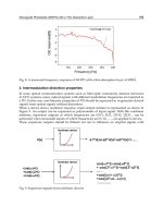
The Sellemeier equation and its coefficients describing the PPLN nonlinear crystal used in
this particular experiment is described in (Jundt 1997) and the accuracy with which it was
able to predict the refractive index of the PPLN crystal and, hence, the phase-matched signal
and idler wavelength pair for a given material temperature and grating period is shown in
Fig. 9. The PPLN crystal used in the experiment had eight discrete grating zones of different
Practical Continuous-Wave Intracavity Optical Parametric Oscillators
307
polling periods written within it and so Fig. 9 comprises eight pairs of signal and idler
curves, each particular pair corresponding to a different grating zone.
Fig. 9. Predicted and measured tuning of the signal and idler wavelengths
An accurate determination of the anticipated signal and idler wavelengths and tuning
ranges is important, not only from the point of view of the end application of the device, as
this information must be first determined before specifying the centre-point and bandwidth
of the coating pertaining to the idler and, of particular importance for the reasons outlined
above, the signal wavelength. The threshold pumping power requirement often rises
substantially at the extremes of the tuning range as signal cavity round trip loss creeps in at
the edge of the coating bandwidth. On condition that it does not compromise overall
performance, it is often prudent to specify a coating bandwidth exceeding the tuning range
over which the parametric process is expected to phase-match in order to obviate this effect.
3.3 Performance evaluation and optimisation
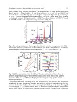
The down-conversion performance of the device is indicated in figure Fig. 10, where the
extracted idler is shown as a function of increased primary diode pump power as is the
circulating pump field both in the presence and absence of down-conversion. The laser and
OPO threshold occurred at a diode pump power of 69 and 310mW respectively. In this latter
case, 5.2W of circulating pump power was present, a figure somewhat larger than the
anticipated threshold field of 3.5W. This is accounted for by sub-confocal focussing of the
pump and signal fields resulting in reduced field intensity. Whilst this leads to the increase
in threshold pump power, the cavity resistance to thermal lensing effects within the PPLN
crystal was significantly reduced leading to more robust performance of the device. Despite
this increase, the primary advantage of the ICOPO approach is still clear. In order to bring
Advances in Optical and Photonic Devices
308
the OPO to threshold in an extra-cavity system, 5.2W of power from the pumping laser
would be required, which itself would therefore require ~10W of primary optical pumping
power. We achieve the same here for just 310mW of primary pump power – a significant
drop indeed. The robust nature of the system is evident from the both linear relationship
between the circulating field and pump power in the absence of parametric down
conversion and the excellent clamping of the pump field once the OPO is above threshold. It
is worth comparing the measured performance of the device as indicated in Fig. 10 with the
theoretical behaviour shown in Fig. 5.
Diode pump power, W
0.0 0.2 0.4 0.6 0.8 1.0
Intracavity field, W
0
5
10
15
20
Extracted idler power, mW
0
20
40
60
80
III
III
OPO On
OPO Off
Laser Threshold: 69mW
OPO Threshold: 310mW
Fig. 10. Extracted idler (triangles) and pump-field with (open circles) and without (closed
circles) operation of the OPO as primary diode pump power is varied. The idler wavelength
was 3.66
μm.
The slightly super-linear nature of the extracted power is a consequence of a thermally-
induced increase in the focal power induced in the Nd crystal reducing the mode size (and
hence, increasing intensity) of the pump field within the PPLN crystal at higher primary
pump powers
At the maximum pump power of 1W the device delivered 70mW of tunable idler through
M2. In order to calculate the total down-converted power (that is, the total signal and idler
power generated) we need to take into account the quantum defect between the signal and
idler waves and for the fact that the idler is generated in both directions within the PPLN
crystal (the ‘other’ direction being lost within the system). The total down-converted power
is therefore
⎟
⎟
⎠
⎞
⎜
⎜
⎝
⎛
+⋅⋅=
s
i
iDC
λ
λ
1P2P (13)
This, for an idler power of 70mW and an idler wavelength of 3.6
μm, corresponds to a total
down-converted power of 476mW from the pump wave into the signal and idler. Recall that
Practical Continuous-Wave Intracavity Optical Parametric Oscillators
309
when mirror M2 was replaced with an optimal output coupler for the pump cavity, 510mW
of power at the pump was obtained. We can therefore take the
down-conversion efficiency of
the device (that is, the fraction of the total obtainable power which is down-converted) to be
476/510 = 93%. A down-conversion efficiency of unity can only be achieved when the OPO
is optimally output coupling the pump field through the parametric effect, which is
achieved when relation (1) is satisfied. For a laser threshold and operating pump power of
69 and 1000mW respectively, the optimal OPO threshold is then 250mW – slightly less than
is the case in this system. As we have said, the stability of the cavity has been improved by
slightly defocusing the pump (and signal) waists within the PPLN crystal which has raised
the OPO threshold to this non-optimal level. The resulting improvement in performance,
however, makes this slight drop in overall efficiency a price worth paying.
Fig. 11. Spontaneous and long-lived bursts of relaxation-oscillations manifesting themselves
on the circulating pump field.
Finally, we turn our attention to the transient stability of the device which was measured by
directing the small amount of pumping field reflected off of the rear face of the beamsplitter
onto a fast photodetector. An example of the resulting trace is shown in Fig. 11. In the
absence of any external perturbation mechanism the pump (and hence signal and idler)
fields exhibited spontaneous and very long-lived bursts of high frequency relaxation
oscillations. This resulted in ~100% modulation of the extracted idler field and erratic
longitudinal mode hopping of the pump field, both of which are most undesirable in the
context of high resolution spectroscopy and renders the device unsuitable for all but mean
power, “crude” mid-IR applications. This is regrettable as in all other respects this system
displays the very many highly desirable characteristics as discussed in sections 1 & 2,, such
as very high efficiency, broad tunability, compact geometry, etc. In order to release the
potential of this technology, a solution to the problem of relaxation oscillations is crucial. Let
us now focus on the nature of these oscillations, the physical processes underpinning their
behaviour and some real-life strategies for their elimination.
Advances in Optical and Photonic Devices
310
4. Transient dynamics and the origin of relaxation-oscillations
Whilst laser systems based upon Nd-doped gain media readily exhibit relaxation
oscillations when substantially perturbed from their steady-state they do not, on the whole,
display any stability problems when left to their own devices. Why is it, then, that a
perfectly stable and well-behaved Nd laser should suddenly become prone to spontaneous
burst of erratic and long-lived relaxation-like oscillations when an OPO is placed within its
cavity?
Fig. 12. Modelled relaxation-oscillation oscillations for a simple Nd-based laser. Photon (a)
and upper-state (b) population evolution over time after the steady state is perturbed.
Experimental observation indicates that the relaxation oscillations displayed by ICOPOs are
different in three key ways to those displayed by the parent pumping laser. They (a) are
very long lived, (b) have a far higher oscillation frequency and (c) occur spontaneously. In
this section we will explore the origins and the nature of relaxation oscillations in cw-
ICOPOs, and thereby find potential strategies for their elimination.
Relaxation oscillations in laser systems are caused by interplay between the energy stored in
the upper state of the lasing transition within the gain medium (n
j
) and that stored within
the optical cavity of the laser due to the circulating pump field (P
p
). In the ICOPO, a third
parameter, the energy stored within the signal cavity due to the circulating signal field (P
s
)
is also introduced. As all of these parameters are cross-coupled, it is useful to investigate
their behaviour by constructing a set of coupled rate equations which can then be solved
numerically with different starting parameters. In the case of the ICOPO, the three coupled
rate equations might be as follows:
(
)
[
]
jpj
u
j
nPknk1
1
n ⋅⋅−−+⋅=
′
τ
(14)
Practical Continuous-Wave Intracavity Optical Parametric Oscillators
311
(
)
⎥
⎥
⎦
⎤
⎢
⎢
⎣
⎡
+
⋅−−
−−
+
⋅
⋅=
′
k1
Pk1
k1
n
P
P
sjjj
p
p
p
σσ
τ
1
(15)
[
]
1−⋅=
′
p
u
s
s
P
P
P
τ
(16)
We say “might” as there is some freedom in the construction of these equations; it is up to
the investigator to choose the way in which the model is normalised. In this particular set of
expressions, n
j
, P
p
and P
s
are assumed to be unity in the steady-state. The cavity photon
lifetimes of the pump and signal cavities are given by
τ
p
,
τ
s
and the upper-state lifetime by
τ
u
. These parameters are normalized to the laser gain medium upper-state lifetime and so
τ
u
is always unity. The factors k and
σ
j
refer to the pumping levels of the laser and OPO with
respect to their threshold conditions:
σ
j
is simply the number of times above threshold at
which the laser is operated, and (k+1) is equal to the number of times at which the OPO is
operated above its threshold level.
Let us initially consider the dynamics of the laser operating in the absence of down-
conversion. In practice this could easily be achieved by blocking the signal cavity without
effecting the operation of the laser. Once running, the laser steady state is ‘plucked’ by
instantaneously halving the circulating field. The numerical model is then allowed to run
until the laser returns to the steady state. The results of this simulation are shown in Fig. 12.
In this model the pump cavity photon lifetime was assumed to be 20ns and the upper-state
lifetime 100
μs (i.e.
τ
u
=1;
τ
p
=0.0002). We can see from the figure that once purturbed, the laser
returns to its steady-state in about 100
μs (i.e. about an upper-state lifetime), and has an
oscillation frequency of about 200kHz. This frequency is determined by the mean of the
upper-state and pump cavity photon lifetimes as:
pu
osc
1
ττ
ω
⋅
∝
(17)
Thus we see that the very long upper-state lifetime (compared to that of the pump cavity
photon) moderates the oscillation frequency to the relatively low ~100’s kHz range. This is
crucial as this relatively low oscillation frequency gives the upper-state population time to
“respond” to the variations in the circulating field. Upon close inspection of Fig. 12, it is clear
that the circulating field and upper-state population are in quadrature-phase. It is a
combination of this phase difference, and, crucially, the modulation depth of the upper-state
population which is the primary damping mechanism returning the system to its steady-state
after a perturbation event. In the case of the system modelled above, the ~±2% modulation
depth of n
j
is sufficient to return the system to its steady-state in about an upper state lifetime.
We now re-run the model using the same laser parameters, but this time in the presence of
intracavity parametric down conversion. Here the system is simulated operating at 2 times
OPO threshold (k=1) with a signal cavity photon lifetime of 40ns (i.e.
τ
s
=0.0004). Fig. 13
shows the transient dynamics of the system after perturbation.
It is obvious that the inclusion of parametric down-conversion within the cavity of the laser
has had an enormous impact upon the transient dynamic behaviour of the system. Even after
20 upper-state lifetimes has passed (i.e. 2ms) the oscillations have still yet to damp away.
Advances in Optical and Photonic Devices
312
Clearly, any system exhibiting such oscillations having triggering mechanism on the order of
or less than this time would display semi-continuous oscillatory behaviour. The time scale
used in Fig. 13 is such that the individual oscillations are not resolvable. These can be seen by
re-plotting the figure over just a few fractions of an upper-state lifetime, as shown in Fig. 14 (a).
We see now that as well as a sharp decline in the damping of the oscillations (giving rise to the
very long oscillation events depicted in Fig. 13), the inclusion of the OPO within the parent
pump laser has led to a very substantial increase in the oscillation frequency.
Fig. 13. Modelled relaxation-oscillation oscillations for a perturbed Nd laser based ICOPO.
Note that the individual oscillations are not visible on this time scale.
We previously stated that in the case of the laser operating in the absence of the OPO the
oscillation frequency was given by the upper-state and pump cavity photon lifetime (17).
Now that the OPO is included in the system the processes giving rise to oscillations have
shifted down a tier from upper-state population → pump cavity power to pump cavity
power → signal cavity power, and therefore the oscillation frequency is now independent of
the upper-state lifetime. It is now solely governed by the pump- and signal- wave cavity
photon lifetimes:
sp
osc
1
ττ
ω
⋅
∝
(18)
The relatively long lifetime of the upper-state, compared to that of the pump- and signal-
cavity photon lifetimes, is now no longer able to moderate the oscillation frequency and the
very short lifetimes of
τ
p
and τ
s
result in such high, order-of-magnitude increased oscillation
frequencies.
Whilst the influence of the upper-state lifetime upon the oscillation frequency has been
removed in the ICOPO, its population response to the changing circulating pump field is
still the primary damping mechanism for the system. This is problematic as the very high
oscillation frequencies have a serious impact upon the ability of the upper-state population
to respond to the rapidly changing circulating field. This is somewhat analogous to the
charge on a large capacitor being unable to track a high-frequency signal placed across its
plates.
The resulting upper-state population is shown in Fig. 14(b). The modulation depth has now
been sharply reduced by two orders of magnitude to just ±0.02%, i.e. just 1 part in 10
4
. This
explains why the oscillations, once induced, carry on for so long – there is very little
damping within the system. It also shows why the oscillations are so easily triggered as only
Practical Continuous-Wave Intracavity Optical Parametric Oscillators
313
very small excursions in the upper-state population are necessary to begin an oscillation
event. Such an excursion could be caused by an acousto-mechanically induced longitudinal
mode-hop of the circulating pump field or small modulation in the primary pumping field.
The long upper-state lifetime (compared to the oscillation period) precludes the use of a
feedback system between the circulating pumping field and external primary pump power
modulation as a mechanism to improve the damping in the system as it acts as an “optical
capacitor”; even 100% modulation of the primary pumping diode scarcely effects the upper-
state population on the time scale of the oscillation periods indicated in Fig. 14.
Fig. 14. Modelled results as in Fig. 13 but also showing the upper-state population and with
a much enlarged time axis.
To summarise: we have shown, through the use of a simple numerical model based upon a
set of three coupled rate-equations, that it is (a) the high oscillation frequencies associated
with ICOPOs, brought about by high-speed energy transfer between the pump and signal
wave cavities via the parametric process, coupled with (b) the weak damping induced onto
these high frequency oscillations by the very long upper-state lifetime of the laser gain
medium which leads to both high susceptibility to, and such long bursts of, relaxation
oscillations in Nd-ICOPOs. In the next section, we examine ways in which the problem of
relaxation oscillations can be circumvented by examining two state-of-the-art cw-ICOPOs
which both display excellent transient stability.
5. Examples of practical, relaxation-oscillation free cw-ICOPOs
In the previous sections we have touched upon the various parameters governing the
operation of cw-ICOPOs and looked in some detail at the physical processes underpinning
the poor transient dynamic behaviour of these devices. We now turn our attention to two
practical examples of state-of-the-art diode-pumped cw-ICOPOs which have been
engineered with particular emphasis on the elimination of the relaxation oscillations which
have to date severely restricted this technology from reaching its full potential.