Báo cáo hóa học: " Research Article Integrating Fingerprint Verification into the Smart Card-Based Healthcare Information System" potx
Bạn đang xem bản rút gọn của tài liệu. Xem và tải ngay bản đầy đủ của tài liệu tại đây (710 KB, 12 trang )
Hindawi Publishing Corporation
EURASIP Journal on Advances in Signal Processing
Volume 2009, Article ID 845893, 12 pages
doi:10.1155/2009/845893
Research Article
Integrating Fingerprint Verification into the Smart Card-Based
Healthcare Information System
Daesung Moon,
1
Yongwha Chung,
2
Sung Bum Pan,
3
and Jin-Won Park
4
1
Biometrics Technology Research Team, ETRI, Daejeon 305-700, South Korea
2
Department of Computer and Information Science, Korea University, Jochiwon, Chungnam 339-700, South Korea
3
Department of Informat ion Control and Instrumentation Engineering, Chosun University, Gwangju 501-759, South Korea
4
School of Games, Hongik University, Jochiwon, ChungNam 339-701, South Korea
Correspondence should be addressed to Yongwha Chung,
Received 10 October 2008; Revised 13 May 2009; Accepted 14 September 2009
Recommended by Stephanie Schuckers
As VLSI technology has been improved, a smart card employing 32-bit processors has been released, and more personal
information such as medical, financial data can be stored in the card. Thus, it becomes important to protect personal information
stored in the card. Verification of the card holder’s identity using a fingerprint has advantages over the present practices of Personal
Identification Numbers (PINs) and passwords. However, the computational workload of fingerprint verification is much heavier
than that of the typical PIN-based solution. In this paper, we consider three strategies to implement fingerprint verification in a
smart card environment and how to distribute the modules of fingerprint verification between the smart card and the card reader.
We first evaluate the number of instructions of each step of a typical fingerprint verification algorithm, and estimate the execution
time of several cryptographic algorithms to guarantee the security/privacy of the fingerprint data transmitted in the smart card
with the client-server environment. Based on the evaluation results, we analyze each scenario with respect to the security level
and the real-time execution requirements in order to implement fingerprint verification in the smart card with the client-server
environment.
Copyright © 2009 Daesung Moon et al. This is an open access article distributed under the Creative Commons Attribution
License, which permits unrestricted use, distribution, and reproduction in any medium, provided the original work is properly
cited.
1. Introduction
A smart card is a credit-card-sized plastic card with an
embedded chip that can be memory or may include a
microprocessor [1]. A microprocessor chip in a smart card
can add, delete, or manipulate information in its memory
and hence offer complex data security functionalities. These
smart cards have been used in many applications such as
health cards, e-passport, and e-ID cards for more than
10 years [2–4]. In this paper, we describe an example
where a smart card is applied in the healthcare information
system. One of the most popular smart card solutions is
Gemalto Cryptoflex JavaCard [5], equipped with a 16-bit
microcontroller (Infineon SLE66CX322P, compatible with
standard SAB 8051 processor) and an additional crypto
processor for RSA and DES computations. The card has
ROM, EEPROM, and RAM. A Java Applet implements the
Chip Authentication Program.
The usual way of obtaining relevant patient data is
connecting to the hospital database. However, we may expe-
rience the situation where no network connection facility
(e.g., ambulance) is available. Also, hospitals cannot open
the patient data stored in the hospital database via Internet
because of the security/privacy of the patient and/or different
network environments. These problems can be solved by
using portable storage devices such as smart cards. That is,
a doctor may take patient information from the smart card
at the time of consultation.
Because of the advantage of the smart card, using the
smart card in healthcare becomes popular in such countries
as France, Germany, and Taiwan. Also, several solutions are
already implemented [5–10]. For example, Taiwan was the
first country introducing the nationwide smart card-based
healthcare information system in 2003. Over 22 million
patient health cards have been issued, as well as over 345 000
health professional cards giving the doctor access to medical
2 EURASIP Journal on Advances in Signal Processing
information. In EU, several projects about smart card-
based healthcare service have been performed such as Sesam
Vitale in France, DENTcard in Germany [7], Transcards [8],
NETLINK [9], and NETC@RDS project [10].
Deployed as of 1998, SESAM-Vitale currently links more
than 223 000 healthcare professionals with the Health Insur-
ance System, for the benefit of millions of insured persons
who have the Vitale card. The NETC@RDS initiative is
devoted to establish new improved healthcare administration
services for mobile citizens across EU. The actual phase
aims at deploying e-health services via the European Health
Insurance Card through a wide trans-European network
simplifying healthcare access procedures. NETC@RDS suc-
cessfully tested the electronic version of the European Health
Insurance Card (EHIC) during its first and second Market
Validation phases in 85 pilot sites of the 10 EU member states.
The Initial Deployment phase of the project—launched on
June 1, 2007—will deploy operational services in all targeted
sites, to total of 305 service sites serving 566 service points
across the 15 participating countries.
NETLINK is a project of the fourth framework pro-
gramme on research and development of European com-
mission HC 4016. Countries involved in the NETLINK
consortium (France, Germany, Italy, and the Province of
Qu
´
ebec) have set up or are in the process of setting up
new nationwide information systems in the healthcare sector
based on the use of modern technologies: smart cards (used
by health professionals and patients), computers (used by
health professionals, hospitals, health Insurance funds), large
networks, trusted third parties (for security purpose).
In the security and the privacy terms, several issues
should be considered in developing the smart card-based
healthcare information system; the ways to certify differ-
ent devices (card, card reader, terminal), the methods to
authenticate users (health professionals and patients), and
the amount of information about a patient to be stored in
the smart card, for example, patient personal information
and emergency contact information. There are many other
issues to consider and the details of other issues can be
found in [11, 12]. In this paper, we consider the methods
to authenticate the cardholder, especially patients in a large-
scale hospital database.
In general, the visible information on the health card
may contain the cardholder’s name, identification number,
birth date, photo, and the card serial number. The contents
inside the card can be divided into four segments: basic
data, health insurance data, medical data, and public health
administration data [13, 14]. The basic data segment stores
the identification information for both the cardholder and
the card itself. The contact person information in case of
emergency and the cryptographic key for security can also
be stored. The health insurance data segment is comprised
of the cardholder’s insurance information and service data
for insurance claims. The medical data segment contains the
information for important physician orders, prescriptions,
and drug allergies. With the advance in the smart card
technology, more medical information can be stored in the
card. Finally, the public health administration data segment
is used for recording personal data pertaining to public
health such as vaccination records and organ donation
notes. Additionally, a separate smart card can be used as an
identification card for a medical staff.
As more information is stored in the smart card, it
becomes important to protect the information it contains.
However, the current card holder verification method in the
healthcare services is based on the password/PIN such as
SESAME-VITALE. Most of people set their passwords/PINs
based on words or numbers that they can easily remember.
Thus, the passwords are easy to crack by guessing or a
simple brute force dictionary attack. Although it is possible
andevenadvisabletokeepdifferent passwords for different
applications, most of people use the same password across
different applications. If a single password is compromised,
it may open many doors. “Long and random” passwords
aremoresecurebuthardertoremember,whichprompts
some users to write them down in accessible locations. Such
passwords also result in more system help desk calls for being
forgotten or expired. Cryptographic techniques such as PKI
[15, 16] can provide very long passwords that need not to be
remembered but are in turn protected by simple passwords,
thus defeating their original purpose.
In recent years, there is an increasing trend of using bio-
metrics, which refers to the personal biological or behavioral
characteristics used for verification or identification [17, 18].
It relies on “something that you are,” and can inherently
differentiate between a verified person and a fraudulent
imposter. The problem of resolving the identity of a person
can be categorized into two distinct types, verification
and identification. Ve rifi catio n matches a person’s claimed
identity to his/her previously enrolled pattern (i.e., “one-
to-one” comparison). However, identification identifies a
person from the entire enrolled population by searching
a database for match (i.e., “one-to-many” comparison). In
this paper, we focus on fingerprint because it is relatively
mature and its scanning unit is cheaper than other biometrics
such as iris [18]. Also, we will focus on verification only
because we assume each patient or medical staff holds
his/her smart card. (Note that, however, fingerprints can
also be applied to healthcare services without the smart
card.)
Since fingerprints cannot be lost or forgotten like
passwords, fingerprints have the potential to offer higher
security and more convenience for user authentication [18].
For example, fingerprints are significantly more difficult to
copy, share, and distribute than passwords. That is, the
main advantage of a fingerprint recognition solution is the
convenience while maintaining sufficiently high security. In
general, security with large data is regarded as higher than
that with small data although this does depend greatly on
the way it is implemented. Fingerprint data size is typically
70 KB for images and 500 B for features, much larger than
that of the password with 10B. Furthermore, large fingerprint
data need not to be memorized. Especially in healthcare
services, fingerprints have additional advantage over the
password. The emergency data set such as his/her blood type
and contact person information can be accessed from the
smart card by using his/her finger in the emergency medical
situation when the patient is unconscious.
EURASIP Journal on Advances in Signal Processing 3
However, fingerprint-based recognition has some dis-
advantages as well [19, 20]. A compromised password can
be canceled and a new password can be issued as often as
desired, whereas people have only 10 fingers. If a fingerprint
is compromised repeatedly, it cannot be replaced eventually
[18]. Finally, in principle, a fingerprint template stolen from
one application may be used in another application. These
issues are especially important in pervasive computing where
the fingerprint data must be carefully protected because
of privacy concerns. Also, we need more computation
to authenticate users with the fingerprint data than the
password.
In large-scale healthcare services, the computational
overhead caused by the deployment of the fingerprint as
well as the protection of the fingerprint data should be
considered. However, only limited research has been carried
out in this direction [21, 22]. In this paper, we consider
the possible scenarios to integrate fingerprints into smart
cards and evaluate each scenario in terms of security,
privacy, and computational overhead (i.e., cost of the smart
card). Also, for the cheapest scenario (i.e., the fingerprint
data is transmitted to a remote server for verification),
the collective performance of fingerprint verification and
the authentication protocol on the client-server model is
analyzed.
The rest of the paper is structured as follows. Section 2
explains the overview of typical fingerprint verification and
three strategies for integrating fingerprints into the smart
card. Sections 3 and 4 describe the fingerprint verification
scenarios for the fingerprint smart card and the client-server
environments, respectively. The results of the performance
evaluation are described in Section 5, and the conclusions are
given in Section 6.
2. Background
2.1. Biometric-Based User Authentication for Healthcare. The
healthcare industry is confronted with solving the legal
requirement to protect medical information of patients.
Medical information is available in the computer network,
thus could be used illegally. Laws call for the protection of
patient privacy and also for standardization of medical data.
Biometrics are expected to be chosen as possible means for
user authentication for healthcare, since biometrics provide
a secure method for patient identification and extracting
personal data for treatment. In a large hospital, there may
occur the following three types of healthcare services that are
related to biometric information.
Access to Personal Medical Information. The largest part of
biometric usage in healthcare industry may be enhancing
individuals’ access to their personal information. It seems
likely that patients will demand access to their information,
while demanding that such information be kept secure.
Medical information may be stored on smart cards or on
networks; in either case, the biometric is a gateway to
personal information.
Emergency Patient Identification. In emergency medical sit-
uations, correct and immediate patient authentication is
critical. For individuals without identification and unable
to communicate, biometric information provides a unique
form of authentication. Developing this type of biometric
identification system includes enrolling a sufficient number
of users to achieve critical mass and the availability of
biometric devices in emergency situations and locations. In
this paper, we assume each patient holds his/her smart card
and the emergency dataset such as his/her blood type and
contact person information can be accessed from the smart
card by using his/her finger in emergency medical situations.
2.2. Fingerprint Verification. The fingerprint is chosen for
verification and for identification in this paper. It is more
mature in terms of the algorithm availability and feasibility.
Fingerprint verification and identification algorithms can
be classified into two categories: image-based and minutiae-
based [17, 18].
A minutiae-based fingerprint verification system has two
phases: enrollment and verification. In the off-line enrollment
phase, an enrolling fingerprint image for each user is
processed, and the features called minutiae are extracted
and stored in a server. In the online verification phase, the
minutiae extracted from an input image is compared to the
stored template, and the result of the comparison is returned.
In general, there are six logical modules involved in the
fingerprint verification system [18]: Fingerprint Acquisition
module, Feature Extraction module, Matching module, Storage
module, Decision module,andTransmission module.
The Fingerprint Acquisition module contains an input
device or a sensor that captures the fingerprint information
from the user. It first refines the fingerprint image against
the image distortion obtained from the fingerprint sensor. A
typical process consists of three stages. The binary conversion
stage applies a lowpass filter to smooth the high frequency
regions of the image and threshold to each subsegment
of the image. The thinning operation generates a one-
pixel-width skeleton image by considering each pixel with
its neighbors. In the positioning operation, the skeleton
obtained is transformed and/or is rotated such that valid
minutiae information can be extracted.
The Feature Extraction module refers to the extraction of
features in the fingerprint image. After this step, some of the
minutiae are detected and stored into a pattern file, which
includes the position, the orientation, and the type (ridge
ending or bifurcation) of the minutiae.
Based on the minutiae, the input fingerprint is compared
with the enrolled fingerprint retrieved from the Storage
module. Actually, the Matching module is composed of the
alignment operation and the matching operation. In order
to match two fingerprints captured with unknown direction
and position, the differences of direction and position
between two fingerprints are detected, and the alignment
between them needs to be accomplished. Therefore, in this
alignment operation, transformations such as translation
and rotation between two fingerprints are estimated, and two
minutiae are aligned according to the estimated parameters.
4 EURASIP Journal on Advances in Signal Processing
If the alignment is performed accurately, the following
matching operation can be regarded as a simple point pattern
matching. In the matching operation, two minutiae are
compared based on their position, orientation, and type.
Then, a matching score is computed. The Decision module
receives the score from the matching module and, using a
confidence value based on the security risks and the risk
policy, interprets the result of the score, thus reaching a
verification decision. The Transmission module provides the
system with the ability to exchange information between all
other modules.
2.3. Integrating Fingerprint into the Smart Card. Fingerprint
technologies have been proposed to strengthen the verifica-
tion mechanisms in general by matching a stored fingerprint
template to a live fingerprint features [17, 18]. In the case
of verification using a smart card, intuition suggests that the
match should be performed by the smart card. However,
this is not always possible because of the complexity of
the fingerprint information, and because of the limited
computational resources available to current smart cards.
In general, three strategies of fingerprint verification can be
identified as follows [23–26].
Store-on-Card. The fingerprint template is stored on a smart
card.Itmustberetrievedandtransmittedtoacardreader
that matches it to the live template acquired from the user by
the fingerprint sensor. Cheap memory cards with no or small
operating systems are generally sufficient for this purpose.
Match-on-Card. The fingerprint template is stored on a
smart card, which also performs the matching with the live
template. Therefore, a microprocessor on the smart card is
necessary. The smart card must contain an operating system
running a suitable match application. It is not possible to
steal information stored in the card since a successful match
enables the use of the certificates on the card without the
need of stored PINs or passwords. Even in the unlikely event
that a card is tampered with; only limited damage is caused
since only that specific user’s credentials are hacked. An
attack on multiple users means that the attacker must get
hold of all users’ cards. In this strategy, the templates are
never exposed to a nontamper proof environment and the
user carries his/her own templates.
System-on-Card. This is a combination of the two previous
strategies. The fingerprint template is stored on a smart
card, which also performs the matching with the live
template, and includes the fingerprint sensor to acquire,
select, and process the live template. This strategy is the
best in terms of the security as everything takes place on
the smart card. Embedding a fingerprint acquisition on a
smart card provides all the privacy and security solutions
but, unfortunately, it is expensive and presents more than
one realization problem.
The benefits derived from the Match-on-Card are valu-
able in themselves: using its own processing capabilities, the
smart card decides if the live template matches the stored
template closely enough to grant the access to its private
data. Nevertheless this scheme presents a danger: we have
no certainty that a fingerprint acquisition has been collected
through live-scan and there is the risk of an attacker’s sniffing
the fingerprint data and later using it to unlock the card in a
replay attack.
3. Fingerprint Verification Scenarios for
the Smart Card-Reader Model
First, simplifying the scenarios between the smart card and
the card reader considered, we assume that the symmetric
and/or asymmetric keys are distributed to the smart card and
the card reader when the system is installed and no further
key exchange is required.
We explained three strategies for integrating the finger-
prints into the smart card in the previous section. In this
section, we consider five different scenarios [20–26, 28, 29].
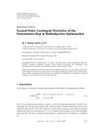
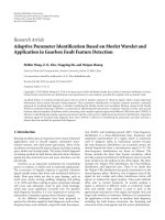
As shown in Figure 1,SCENARIO1andSCENARIO2are
Store-on-Card strategies because the smart card stores the
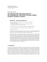
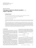
fingerprint template. Also, as shown in Figure 2,SCENARIO
3 and SCENARIO 4 are Match-on-Card strategies because
the matching module takes place on the smart card. Finally,
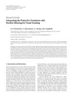
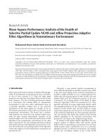
SCENARIO 5 is the System-on-Card strategy (Figure 3).
Within the Store-on-Card and the Match-on-Card scenarios,
we can differentiate those in which the fingerprint sensor is
built into the smart card (SCENARIO 2 and SCENARIO 4)
and those where it is in the card reader (SCENARIO 1 and
SCENARIO 3).
Store-on-Card: SCENARIO 1 and SCENARIO 2. In SCE-
NARIO 1, the fingerprint sensor is built into the card reader.
The user template is transferred from the card to the reader.
The reader takes the fingerprint image provided by its built-
in fingerprint sensor, performs the feature extraction, and
also matches the features to the template provided by the
card. The reader then informs the card whether verification
has been successful or not.
On the other hand, the fingerprint sensor in SCENARIO
2 is built into the card. The fingerprint image and the user
template are transferred from the card to the reader. The
reader performs feature extraction and matches the features
to the template. The reader then informs the card whether
verification has been successful or not.
Match-on-Card: SCENARIO 3 and SCENARIO 4. In SCE-
NARIO 3, the fingerprint sensor is built into the card
reader. The reader takes the image provided by the built-
in fingerprint sensor and performs feature extraction. The
extracted features are sent to the card, which then performs
the matching module and reaches the verification decision
module.
The fingerprint sensor in SCENARIO 4 is built into the
card. The fingerprint image is transferred from the card
to the reader. The reader performs the feature extraction
module only, and transfers the extracted features back to the
card. The card then performs the matching module.
EURASIP Journal on Advances in Signal Processing 5
Storage
E
AES
(template)
Sig
ECC
(SHA1(template))
E
AES
(yes/no)
Fingerprint
acquisition
Feature
extraction
Matching
& decision
Fingerprint
acquisition
Storage
E
AES
(raw data)
Sig
ECC
(SHA1(raw data))
E
AES
(template)
Sig
ECC
(SHA1(template))
E
AES
(yes/no)
Feature
extraction
Matching
& decision
Raw data
Features
Features
Card Reader Card Reader
Scenario 1 Scenario 2
Figure 1: Illustration of the integrating scenarios [23–26] for store-on-card and the corresponding X9.84 [27] implementations.
Storage
Te m p l a t e
Yes/no
Fingerprint
acquisition
Feature
extraction
Matching
& decision
Fingerprint
acquisition
Storage
E
AES
(raw data)
Sig
ECC
(SHA1(raw data))
E
AES
(features)
Sig
ECC
(SHA1(features))
Yes/no
Feature
extraction
Matching
& decision
Raw dataRaw data
Te m p l a t e
Card Reader Card Reader
Scenario 3 Scenario 4
E
AES
(features)
Sig
ECC
(SHA1(features))
Figure 2: Illustration of the integrating scenarios [23–26] for match-on-card and the corresponding X9.84 [27] implementations.
Storage
Te m p l a t e
Yes/no
Fingerprint
acquisition
Feature
extraction
Matching
& decision
Features
Raw data
Card Reader
Scenario 5
Figure 3: Illustration of the integrating scenarios [23–26] for system-on-card and the corresponding X9.84 [27] implementations.
6 EURASIP Journal on Advances in Signal Processing
System-on-Card: SCENARIO 5. SCENARIO 5 is System-on-
Card: that is, all fingerprint verification modules take place
on the card.
4. Fingerprint Verification Scenarios for
the Large-Scale Client-Server Model
As we explained in Section 1, we also consider the client-
server model for remote user authentication using finger-
print. Especially, we consider the healthcare information
system using the cheapest fingerprint-based smart cards,
that is, SCENARIO 1. In spite of guaranteeing higher
security level than SCENARIO 1, other scenarios may not
be right choices for large-scale applications such as national
healthcare services or large hospitals having millions of
patients due to the high implementation cost.
The client-server model for remote user authentication
using the SCENARIO 1-based fingerprint card must guar-
antee the security/privacy as well as the real-time execution
requirements. To satisfy those requirements, we first consider
possible scenarios for remote fingerprint verification in terms
of assigning the tasks of the fingerprint verification to
each entity (i.e., client and server). Then, we evaluate the
performance of each scenario.
Note that, to provide higher security level in the remote
healthcare service, we assume the three-way verification
method among the smart card fingerprint data, the live
fingerprint data and the fingerprint data stored in the central
DB. Also, we denote the three possible fingerprint verifica-
tion scenarios for the client-server model as SCENARIO 1
1,
SCENARIO 1
2, and SCENARIO 1 3, respectively.
Following assumptions are made to simplify the explana-
tion.
(1) Between the client and the server, the same master key
is shared when the system is installed.
(2) Entity authentication is completed using proper
methods such as trusted Certificate Authority (CA).
(3) The user authentication service is assumed to be
requested by the client at which the board control
investigator is working.
(4) The execution time to perform some cryptography
mechanisms to protect the fingerprint features stored
in the smart card and in the server’s database is not
considered because this research focuses only on the
protection of the fingerprint data transmitted.
In fact, these assumptions are reasonable, since the master
key sharing operation (described in Assumption 1) needs to
be executed only once, and the time for protecting the stored
fingerprint data (described in Assumption 4) is negligible.
For the purpose of explanation, we define first the following
notations:
N: a nonce generated randomly in the client and used
as a “challenge;”
K
m
: a master key shared by both the sensor and the
client;
f (N): a simple function to generate a “response” for
N;
K
s
: a shared session key generated for each transmis-
sion;
C
Fe: a fingerprint feature stored in the biometric
health card;
L
Fe: a fingerprint feature extracted from the live
fingerprint image;
S
Fe: a fingerprint feature stored in the DB;
L
Fi: a live fingerprint image;
Mat
CL: a matching result between C Fe and L Fe;
Mat
CS: a matching result between C Fe and S Fe.
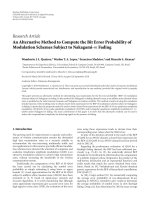
SCENARIO 1
1, Store-on-Card/the Server Does Everything.
In SCENARIO 1
1 as shown in Figure 4, the sensor attached
to the client captures a live fingerprint image, and the client
extracts some features from the image. Then, the client sends
L
Fe and C Fe to the server after applying the encryption and
digital signature with the same key received from the server.
After verifying the signature for L
Fe and C Fe and
decrypting these fingerprint features, the server performs
two comparisons with C
Fe – S Fe and C Fe – L Fe.After
checking the two matching results, the server returns a final
result to the client. Note that this is a typical scenario of
assigning the fingerprint verification tasks to the client-server
model and requires five sets of communications for data
transmission. This scenario can improve the security level
of the fingerprint authentication system because the server
can be more secure than the client. A server should be
protected by the security experts, while a client maintained
by an individual user may be more vulnerable to several
attackssuchasTrojanHorse[12–14]. On the other hand,
the computational workload of the server in this scenario
increases as the number of clients increases.
SCENARIO 1
2, Store-on-Card/Extraction by the Client and
Matching by the Server. Unlike SCENARIO 1
1, in SCE-
NARIO 1
2 as shown in Figure 5, the comparison with C Fe –
L
Fe and C Fe – S Fe is executed in the client and the server,
respectively. In this scenario, the client sends only C
Fe to
the server and calculates the matching score between Mat
CS
received from the server and Mat
CL resulted in the client.
SCENARIO 1
3, Store-on-Card/The Client Does Everything.
In SCENARIO 1
3 as shown in Figure 6, all the tasks except
fingerprint acquisition are executed in the client. After
encrypting the fingerprint features of the requested user
stored in the server’s database, the server only transmits it to
the client. Thus, this scenario can reduce the workload of the
server significantly by distributing the fingerprint authenti-
cation tasks into the clients. However, the security level of the
fingerprint authentication system can be degraded because
the client, which is more vulnerable to several attacks than
the server, executes most of the tasks and the system depends
on the security of keys stored in the client.
EURASIP Journal on Advances in Signal Processing 7
Health card
Fingerprint
sensor
Card reader Client
(1) C
Fe (3) Req Session Key E
km
(N)
(4) E
km
(ks) Sign(f(N))
(8) E
ks
(Sign(C Fe))
(9) E
ks
(Sign(L Fe))
(16) E
ks
(Sign(result))
Server
DB
(2) Input live fingerprint of patient
(5) Encrypt and generate signature about C
Fe
(6) Feature extraction about L
Fi
(7) Encrypt and generate signature about L
Fe
(10) Decrypt and verify signature about C
Fe
(11) Decrypt and verify signature about L
Fe
(12) Matching between L
Fe and C Fe
(13) Matching between S
Fe and C Fe
(14) Fusion between Mat
CS and Mat CL
(15) Encrypt and generate signature about result
Figure 4: Illustration of SCENARIO 1 1.
Health card
Fingerprint
sensor
Card reader
Client
(1) C
Fe
(3) Req
Session Key E
km
(N)
(4) E
km
(ks) Sign(f(N))
(6) E
ks
(Sign(C Fe))
(10) E
ks
(Sign(Mat CS))
Server
DB
(2) Input live fingerprint of patient
(5) Encrypt and generate signature about C
Fe
(11) Feature extraction about L
Fi
(13) Decrypt and verify signature about Mat
CS
(7) Decrypt and verify signature about C
Fe
(12) Matching between C
Fe and L Fe
(8) Matching between C
Fe and S Fe
(14) Fusion between Mat
CS and Mat CL
(9) Encrypt and generate signature about Mat
CS
Figure 5: Illustration of SCENARIO 1 2.
Table 1: Number of instructions required for fingerprint verifica-
tion [25].
Number of Instructions
Feature Extraction 451739 250
Feature Matching 21 164 578
Table 2: Number of instructions and estimated time for fingerprint
verification.
Step
Estimated time on
ARM7TDMI
Estimated time on
8051
Feature Extraction
7.5 seconds 195 seconds
Feature Matching
0.3 seconds 7.8 seconds
5. Performance Evaluation
5.1. Evaluation of Fingerprint Verification and the Cryp-
tographic Modules. A fingerprint-based smart card system
for user verification must guarantee the user’s privacy and
provide sufficient authentication for access to patient data as
well as the real-time execution requirements. To satisfy the
requirements, we first evaluate the logical modules involved
in the fingerprint verification system and the cryptographic
modules for guaranteeing the integrity and confidentiality of
the sensitive fingerprint data transmitted between the smart
card and the card reader (see Section 3).
For secure transmission of the fingerprint data, we
consider ANSI X.9.84, which is the security standard for
fingerprint systems. The ANSI X.9.84 Fingerprint Informa-
tion Management and Security standard [22] covers the
requirements for managing and securing biometric data
(fingerprint, iris, voiceprint, etc.) for customer identification
and employee verification, mainly in the financial industry.
In addition, this standard identifies the digital signature
and encryption to provide both integrity and privacy of
the fingerprint data. Specifically, 128-bit Advanced Encryp-
tion Standard (AES) and Elliptic Curve Digital Signature
Algorithm (EDCSA) [8, 9] are considered as our symmet-
ric encryption algorithm and digital signature and hash
algorithm, respectively (see Figures 1–3). ECDSA is the
elliptic curve analogue of the Digital Signature Algorithm
(DSA). It is the most widely standardized elliptic curve-based
signature scheme, appearing in ANSI X9.62, FIPS 186-2,
IEEE 1363-2000, and the ISO/IEC 15946-2 standards as well
as several draft standards. Because the most time consuming
operations of ECDSA are ECC and the hash operation, we
8 EURASIP Journal on Advances in Signal Processing
Health card
Fingerprint
sensor
Card reader Client
(1) C
Fe
(3) Req
Session Key and S Fe E
km
(N)
(5) E
km
(ks) Sign(f(N))E
ks
(Sign(S Fe))
Server
DB
(2) Input live fingerprint of Patient
(7) Feature extraction about L
Fi
(6) Decrypt and verify signature about S
Fe
(8) Matching between C
Fe and L Fe
(9) Matching between C
Fe and S Fe
(10) Fusion between Mat
CS and Mat CL
(4) Encrypt and generate signature about S
Fe
Figure 6: Illustration of SCENARIO 1 3.
Table 3: Number of Instructions and Cycles Required for AES.
AES (128-bit)
Encryption Decryption
No. of instructions No. of cycles No. of instructions No. of cycles
ARM7TDMI
140 KB 292 889 168 485 763 071 406 011 432 690 034 743
1 KB 2 131 620 3 535 199 2 952 268 5 017 575
confine our evaluation to them. Here, SHA1 is used as the
hash algorithm.
Ta ble 1 shows the number of instructions of each task
in fingerprint verification measured on an instruction sim-
ulator, SimpleScalar [30]. Based on Ta bl e 1,wecancompute
the estimated execution time of each task on each processor.
Finally, the time to acquire a fingerprint image through the
fingerprint sensor is assumed to be about 1 second. Note
that the feature extraction module requires a lot of integer
operations for image processing, and the computational
workload of this module occupies 96% of the total workload
of fingerprint verification.
In order to show the performance requirement of the in-
card processor, the number of instructions and the estimated
execution time on the 8-bit Intel-8051 and 32-bit ARM7-
based smart cards are summarized in Ta bl e 2 . According to
Ta ble 2 , it is impossible to assign the feature extraction or the
matching step as well as the preprocessing to the 8051 chip.
This is because the computation using the fingerprint data
requires a large amount of memory and time. Thus, we adopt
ARM7 to realize the Match-on-Card [25], which shows an
improved result. Actually, the 32-bit smart card is somewhat
expensive to be applied for the ordinary system. Nevertheless,
it can be a good solution for the system that should guarantee
very high level of security such as in E-Health, E-Business,
and E-Government.
Because of the limited processing power of the in-card
processor, all of the three steps above cannot be assigned to
the in-card processor. Instead, we consider assigning only
the third step, matching, to the in-card processor. This is
because the first two steps involve rigid image processing
computation, which is too exhaustive to be executed in the
in-card processor. These computation steps can be easily
carried out in real-time by a fingerprint capture device or
a card reader equipped with at least a 500 MIPS processor.
Therefore, all of the computational steps can be performed in
real-time, and the smart card can encapsulate the fingerprint
data and perform the comparison securely inside the card.
Also, Ta bl e 3 and 4 show the number of instructions
of the cryptography modules measured on the simula-
tor ARMulator [31]. The cryptographic modules need to
guarantee the privacy of the fingerprint data transmitted
between the smart card and the card reader. The sizes
of the fingerprint image and the features are 140 KB and
about 1 KB, respectively. As shown in Tab le 3, the time to
require to encrypt and decrypt the fingerprint image using
the AES algorithm are about 9.7 seconds and 13.8 seconds
in the ARM7TDMI core, respectively. By comparison, the
features require only 0.06 second (encryption) and 0.1
second (decryption). Also, as shown in Ta bl e 4,SHA1,and
ECC for the digital signature can be executed in real-time
for the fingerprint image and the features. If a core of the
smart card is the 8051 chip, it is impossible to execute
the AES algorithm for the fingerprint image in real-time.
Furthermore, the digital signature cannot be executed in
real-time because the time to require for the ECC algorithm
is about 8 seconds.
Finally, the following configuration is assumed to eval-
uate the performance of each scenario of the client-server
model (see Section 4). First, the client and the server have
Pentium 4 (2 GHz) processor and Xeon (3 GHz) processor,
respectively. The transmission speed of the Internet is
assumed to be 10 Mbps. 128-bit AES, 1024-bit ECC, and
SHA1 [15, 16] are used as symmetric encryption algorithm,
digital signature algorithm, and hash algorithm, respectively,
in order to guarantee both the integrity and the confiden-
tiality of the transmitted information. Also, we examined
each scenario on the fingerprint images captured with an
EURASIP Journal on Advances in Signal Processing 9
Table 4: Number of instructions and cycles required for the digital signature.
SHA1 ECC (1024-bit)
No. of instruction No. of cycle No. of instruction No. of cycle
ARM7TDMI
140 KB 3 091 169 4 709 469 12 528 848 20 327 978
1 KB 26 990 42 165 12 528 848 20 327 978
Table 5: Evaluation data of cryptography algorithms (Byte, milisecond).
Generate signature Verify signature Size of signature AES encrypt AES decrypt
Pentium 4
1 KB 6.359 33.656 48 3.0 4.0
140 KB 74.703 98.922 47 234.0 328.0
Xeon
1 KB 3.656 19.797 48 1.0 2.0
140 KB 42.844 59.046 47 125.0 218.0
optical scanner manufactured by NitGen [32]. The size of
the fingerprint image and the fingerprint feature is about
140 KByte and 1 KByte, respectively. Finally, the disk access
time of the fingerprint data stored in the server is assumed to
be 50 miliseconds.
Ta ble 5 shows the measured execution time of several
cryptography algorithms used in our evaluation. These data
are measured by arithmetic mean of 1 000 executions on each
platform.
5.2. Performance Evaluation Results for the Smart Card-
Reader Model. As explained earlier, in the case of the smart
card with the 8051 chip, secure transmission of both the
fingerprint image and the features for all scenarios cannot
be guaranteed because ECDSA, especially the ECC and the
SHA1 algorithms, cannot be executed in real time.
When the smart card employs the ARM7TDMI core [29],
the performance of each of five scenarios is evaluated as
follows.
In SCENARIO 1, the cryptographic processes for guar-
anteeing the integrity and confidentiality of the sensitive
fingerprint data transmitted between the smart card and
the card reader can be executed in real-time because only
the template stored in the smart card is transferred. It is,
however, the Store-on-Card strategy that all the fingerprint
verification modules except the storage module are executed
in the card reader. Therefore, the fingerprint template stored
in the smart card needs to be insecurely released into an
external card reader in order to be compared with an input
fingerprint.
SCENARIO 2 has the lowest security level because it is
also the Store-on-Card strategies that the smart card only
stores the fingerprint template. Furthermore, in SCENARIO
2, secure transmission of the fingerprint image captured
by the fingerprint sensor within the smart card cannot be
guaranteed since the fingerprint sensor is built into the smart
card. In this case, ECDSA, especially the ECC and the SHA1
algorithms, cannot be executed in real-time.
On the other hand, SCENARIO 3 is the most proper
one to integrate fingerprint verification with the smart card
because it guarantees higher security level than with the
Store-on-Card. It also executes the cryptographic modules
for secure transmission in real time because of transferring
only the fingerprint features extracted in the card reader.
SCENARIO 4, like SCENARIO 2 cannot guarantee the
security and real-time transmission of the fingerprint image
captured by the fingerprint sensor within the smart card.
SCENARIO 5 is the System-on-Card that all the fin-
gerprint verification modules take place on the card. This
scenario is the best in terms of security as everything takes
place on the smart card. As explained in Section 2.3, it is
expensive and presents more than one realization problem.
Even if the smart card employs the ARM7TDMI core,
SCENARIO 5 cannot be executed in real-time because the
feature extraction module of fingerprint verification is time
consuming as shown in Ta bl e 2.
5.3. Performance Evaluation Results for the Client-Server
Model. For each of the fingerprint authentication scenarios
described in the previous section, we assume that the
response time must be less than 5 seconds for real-time
execution. As we expect, the server processes most of
the time-consuming tasks in SCENARIO 1
1, whereas the
clients have the heavy workload in SCENARIO 1
2. The
extreme case is SCENARIO 1
3 where the clients do almost
everything. However, the security of SCENARIO 1
3is
weaker.
In this section, we will evaluate the three scenarios in
terms of the response time versus workloads imposed on
the server. In other words, we will investigate the maximum
workload that the server can handle with less than 5 seconds
response time, or system time in queueing theory of each
scenario. We adopt M/D/1 queueing results assuming that
the clients request services to the server in random fashion,
but the server processes the jobs in deterministic fashion.
In an M/D/1 system, the response time is given by
w
=
1
μ
+
λ
2μ
μ − λ
,(1)
where W is the response time (or the system time), μ is the
service rate, and λ is the arrival rate. Here, λ is the job request
rate to the server by the clients, and λ is assumed to increase
as the number of clients increases.
10 EURASIP Journal on Advances in Signal Processing
In SCENARIO 1
1, fingerprint acquiring (1 000 mil-
liseconds) is done by the sensor, whereas feature extraction
(225 milliseconds), generation of signature for feature
(6.359 milliseconds), and encryption (3.0 milliseconds)
tasks are done by the client. Additionally, we consider the
communication setup time for sending and receiving data
from the server as st and the data transmission time to be
1.6 milliseconds: that is, 2
× 0.8 milliseconds or 2 times of
1 KB by 10 Mbps Internet transmission. Thus, the total sums
to 1 235.959 + 5 st milliseconds. We take values for st of 1,
5, or 50 millisecond(s) depending on the communication
environments. On the server side, decryption for live feature
(2.0 milliseconds), decryption for smart card feature (2.0
milliseconds), verifying the signs for live feature and smart
card feature (2
× 19.797 milliseconds), matching twice (2
× 6.5 milliseconds), and data transmission time of 1.6
milliseconds and the communication setup time (5 st) sum
to 58.194 + 5 st, which equal the service time (1/μ). Thus, we
may build the response time (W) in the M/D/1 system as
w
= 1235.959 + 5st +
1
μ
+
λ
2μ
μ − λ
< 5000. (2)
If we take st be 1 millisecond in (2), we have λ being less
than 0.01569 in order to meet the total response time being
less than 5 seconds. Here, the workload can be interpreted as
the number of job requests by the clients to the server in unit
time (millisecond).
A similar approach can be applied to SCENARIO 1
2:
fingerprint acquiring (1000 milliseconds) is done by the
sensor, whereas live feature extraction (225 milliseconds),
decryption for smart card feature (4.0 milliseconds), veri-
fying sign for smart card feature (33.656 milliseconds), and
matching smart card versus live feature (10 milliseconds)
tasks are done by the client. Additionally, we consider the
communication setup time for sending and receiving data
from the server as st and the data transmission time (0.8
millisecond, 1 time of 1 KB by 10 Mbps Internet transmis-
sion). Thus, the total sums to 1 273.456 + 4 st milliseconds.
We take values for st of 1, 5, or 50 millisecond(s) depending
on the communication environments. On the server side,
decryption for smart card feature (2.0 milliseconds), verify
the sign for smart card feature (19.797 milliseconds),
matching once (6.5 milliseconds) and data transmission
time of 0.8 millisecond, and the communication setup time
(4 st) sum to 29.097 + 4 st, which plays the service time (1/μ).
Thus, we may build the response time (W) in the M/D/1
system as
w
= 1273.456 + 4st +
1
μ
+
λ
2μ
μ − λ
< 5000. (3)
If we take st to be 1 millisecond in (3), μ must be less
than 0.03008 in order to meet the total response time being
less than 5 seconds.
In SCENARIO 1
3, the server is doing practically nothing
except encrypting the stored template and sending the
encrypted data to the clients. Fingerprint acquiring (1000
milliseconds) is done by the sensor, whereas decryption for
DB feature (4.0 milliseconds), verifying signature for DB
Table 6: Summary of performance evaluation 1 (st = 1ms).
SCENARIO 1 11213
Maximum workload 0.01569 0.03008 0.15010
Relative workload 1 1.92 9.57
Table 7: Summary of performance evaluation 2 (st = 5millisec-
onds).
SCENARIO 1 11213
Maximum workload 0.01188 0.02023 0.06810
Relative workload 1 1.70 5.73
Table 8: Summary of performance evaluation 3 (st = 50 millisec-
onds).
SCENARIO 1 11213
Maximum workload 0.00310 0.00422 0.00942
Relative workload 1 1.36 3.04
feature (33.656 milliseconds), decryption for smart card
feature (4.0 milliseconds), verifying sign for smart card
feature (33.656 milliseconds), live feature extraction (225
milliseconds) and 2 times of matching (2
× 10 milliseconds)
tasks are done by the client. Additionally, we consider
the communication setup time for sending and receiving
signals from the server as st. Thus, the total sums to
1 320.312 + 2 st milliseconds. We take values for st of 1,
5, or 50 millisecond(s) depending on the communication
environments. On the server side, encryption for DB feature
(1.0 millisecond), generating signature for DB feature (3.656
millisecond(s)), and the communication setup time (2 st)
sum to 4.656 + 2 st, which plays the service time (1/μ). Thus,
we may build the response time (W) in the M/D/1 system as
w
= 1320.312 + 2st +
1
μ
+
λ
2μ
μ − λ
< 5000. (4)
Fixing st be 1 millisecond in (4), we have λ being less
than 0.1501 in order to meet the total response time being
less than 5 seconds.
Summarizing the results obtained in this section is
depictedinTables6–8.AsweseeinTab le 6 , the server can
handle the lowest level of workload with SCENARIO 1
1,
whereas the server can handle 9.57 times heavier workload
with SCENARIO 1
3. In most reasonable case of SCENARIO
1
2, the server can handle 1.92 times heavier workload
compared to the case of SCENARIO 1
1.
Another interesting result comes when we vary the
communication setup time from 1 ms to 5 ms and 50 ms,
as shown in Tables 7 and 8. As we notice in Tables 7
and 8, the workload that the server can handle within the
specified time constraint of 5 seconds changes dramatically
as the communication setup time increases. When the
communication setup time becomes 5 milliseconds, the
server can handle only 5.73 times heavier workload with
SCENARIO 1
3 compared to those with SCENARIO 1 1. It
becomes worse with the communication setup time being
50 milliseconds, where the server can handle only 3.04
EURASIP Journal on Advances in Signal Processing 11
times heavier workload with SCENARIO 1
3comparedto
those with SCENARIO 1
1 even though almost everything is
performed in the clients with SCENARIO 1
3.
6. Conclusions
We focus on examining which strategies are most appro-
priate to guarantee the privacy as well as the real time
execution requirements for smart card with client-server
based fingerprint verification in healthcare information
systems. First, five scenarios with three different strategies
for integrating fingerprints into a smart card system were
examined. Then, three scenarios for implementing of the
fingerprint authentication service for large-scale applications
were examined with increasing numbers of clients.
Typical task assignment scenarios for fingerprint verifica-
tion were considered to protect the fingerprint information
transmitted and to guarantee both the integrity and the
confidentiality of the fingerprint data. The workload char-
acteristics of fingerprint verification and the authentication
protocol were obtained by measuring the performance of the
primitive operations on an ARM7TDMI-based smart card, a
Pentium4-based PC, and a Xeon-based server, respectively.
Based on these measured performance, the workload of
each scenario of the task assignment was computed and
was applied to the smart card reader model. Then, the
collective performance of each scenario was analyzed using
the workload computed for each scenario.
The analysis results showed that the scenario where the
match operation is performed on the smart card with the
fingerprint sensor being built into the card reader is the
most beneficial in the smart card-card reader model. For
large-scale applications, however, this scenario may not be
applicable due to the high implementation cost. In the
client-server model, the server could handle the lowest
level of workload when it does decryption, verification
and matching. By comparison, the server can handle 9.57
times heavier workload when the clients do decryption,
verification, and matching.
Acknowledgments
This research was supported by The Ministry of Knowledge
Economy (MKE), South Korea, under the Home Network
Research Center (HNRC) Information Technology Research
Center (ITRC) support program supervised by the National
IT Industry Promotion Agency (NIPA), (NIPA -2009-C1090-
0902-0035).
References
[1] H.DreifusandT.Monk,Smart Cards, John Wiley & Sons, New
York, NY, USA, 1997.
[2] A. Alkhateeb, T. Takahashi, S. Mandil, and Y. Sekita, “The
changing role of health care IC card systems,” Computer
Methods & Programs in Biomedicine, vol. 60, no. 2, pp. 83–92,
1999.
[3] G. Kardas and E. T. Tunali, “Design and implementation of
a smart card based healthcare information system,” Computer
Methods & Programs in Biomedicine, vol. 81, no. 1, pp. 66–78,
2006.
[4] M. Marschollek and E. Demirbilek, “Providing longitudinal
health care information with the new German Health Card—a
pilot system to track patient pathways,” Computer Methods &
Programs in Biomedicine, vol. 81, no. 3, pp. 266–271, 2006.
[5] Gemalto, />[6] Health Smart Card, />[7] C. Pagetti, et al., “A European health card,” Final Report, Euro-
pean Parliament, Directorate General for Research, Document
for STOA Panel, 2001.
[8] Transcards Project, />programme
eng.asp.
[9] Netlink Project, />pres
.htm.
[10] Netcards, Trans-European Healthcare Facility Service for
Mobile Citizens, />[11] G. Kardas and E. T. Tunali, “Design and implementation of
a smart card based healthcare information system,” Computer
Methods & Programs in Biomedicine, vol. 81, no. 1, pp. 66–78,
2006.
[12] O. Rienhoff, Integrated Circuit Health Data Cards (Smart
Cards): A Primer for Health Professionals, PAHO, Washington,
DC, USA, 2003.
[13] Health Insurance Portability and Accountability Act of 1996
(U.S.), Public Law no. 104-191, 110 Stat. 1936, HIPAA.
[14] B. Barber, “Patient data and security: an overview,” Interna-
tional Journal of Medical Informatics, vol. 49, no. 1, pp. 19–30,
1998.
[15] W. Stallings, Cryptography and Network Security: Principles
and Practice, Prentice-Hall, Upper Saddle River, NJ, USA,
2003.
[16] D. Hankerson, A. Menezes, and S. Vanstone, Guide to Elliptic
Curve Cryptography, Springer, New York, NY, USA, 2003.
[17] S. Nanavati, M. Thieme, and R. Nanavati, Biometrics: Identity
VerificationinaNetworkedWorld, John Wiley & Sons, New
York, NY, USA, 2002.
[18] D. Maltoni, D. Maio, A. Jain, and S. Prabhakar, Handbook of
Fingerprint Recognition, Springer, New York, NY, USA, 2003.
[19] R. M. Bolle, J. H. Connell, and N. K. Ratha, “Biometric perils
and patches,” Pattern Recognition, vol. 35, no. 12, pp. 2727–
2738, 2002.
[20] B. Schneier, “The uses and abuses of biometrics,” Communica-
tions of the ACM, vol. 42, no. 8, p. 136, 1999.
[21] S. Prabhakar, S. Pankanti, and A. K. Jain, “Biometric recog-
nition: security and privacy concerns,” IEEE Security and
Privacy, vol. 1, no. 2, pp. 33–42, 2003.
[22] S. de Lusignan, T. Chan, A. Theadom, and N. Dhoul,
“The roles of policy and professionalism in the protection
of processed clinical data: a literature review,” International
Journal of Medical Informatics, vol. 76, no. 4, pp. 261–268,
2007.
[23] Y. S. Moon, H. C. Ho, K. L. Ng, S. F. Wan, and S. T. Wong,
“Collaborative fingerprint authentication by smart card and
a trusted host,” in Proceedings of the Canadian Conference on
Electrical and Computer Engineering, vol. 1, pp. 108–112, 2000.
[24] L. Rila and C. Mitchell, “Security analysis of smartcard
to card reader communications for biometric cardholder
authentication,” in Proceedings of the 5th Smart Card Research
and Advanced Application Conference (CARDIS ’02), pp. 19–
28, 2002.
[25] D. Moon, et al., “Performance analysis of the Match-on-Card
system for the fingerprint verification,” in Proceedings of the
12 EURASIP Journal on Advances in Signal Processing
International Workshop on Information Security Applications,
pp. 449–459, 2001.
[26] Y. Chung, D. Moon, T. Kim, and J W. Park, “Workload
dispatch planning for real-time fingerprint authentication
on a sensor-client-server model,” in Proceedings of the 5th
International Conference on Parallel and Distributed Comput-
ing: Applications and Technologies (PDCAT ’04), vol. 3320 of
Lecture Notes in Computer Science, pp. 833–838, 2004.
[27] X.9.84, />[28]A.D.Boyd,C.Hosner,D.A.Hunscher,B.D.Athey,D.J.
Clauw, and L. A. Green, “An ‘Honest Broker’ mechanism
to maintain privacy for patient care and academic medical
research,” International Journal of Medical Informatics, vol. 76,
no. 5-6, pp. 407–411, 2007.
[29] C. Quantin, O. Cohen, B. Riandey, and F A. Allaert, “Unique
Patient Concept: a key choice for European epidemiology,”
International Journal of Medical Informatics, vol. 76, no. 5-6,
pp. 419–426, 2007.
[30] D. Burger and T. Austin, “The simplescalar tool set, version
2.0,” Tech. Rep., University of Wisconsin, Madison, Wis, USA,
1997.
[31] ARM, />[32] Nitgen, />