Robotics and Automation in Construction 2012 Part 10 doc
Bạn đang xem bản rút gọn của tài liệu. Xem và tải ngay bản đầy đủ của tài liệu tại đây (4.19 MB, 30 trang )
Development of Adaptive Construction Structure by Variable Geometry Truss
263
4. Develpment of a movable monument applying VGT mechanism exhibited
in Expo 2005
AS for the other practical example applying VGT mechanism, Development of a movable
monument is mentioned in this paragraph.
4.1 Outline of a movable monument
4.1.1 Background and outline of the development
Expo 2005 in Aichi, Japan ended successfully about 3 year ago, with more than two million
people attending from around the world. There were various exhibitions, entertainments,
attractive buildings, new technology and events based on the theme of “Nature’s wisdom”.
One remarkable technology displayed at the Expo was the application and performance of
automated robots. For example, music-playing robots in a group, automatic cleaning robots,
guard robots, etc. These scenes might be imagined a the future and such technologies
continue to be developed.
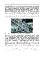
In the Japanese zone of the Aichi prefecture pavilion near the center of the exhibition as
showing in Fig.15, there was a large monument in the shape of a traditional Karakuri doll
beckoning visitors inside. The exhibit here was called “Dancing Tower with Karakuri doll
Performance”, and was exhibited as a symbol of Aichi district’s culture, harmonizing
traditional technology with revolutionary new ones.
Fig. 15. Overall Map of Expo Site and Nagakute Aichi Prefecture Pavilion exhibited Movable
Monument (From the Expo 2005 Pamphlet of Aichi Prefecture in Japan)
Robotics and Automation in Construction
264
For the Nagakute Aichi prefecture pavilion, the Expo organizers requested a design for a
monument comprising a symbol tower to attract visitors to the pavilion. We proposed a
movable monument whose shape could be changed variably and irregularly. A large
movable monument using VGT was selected as a very unique and attractive monument.
A picture of the Expo site and the Nagakute Aichi Prefecture pavilion where the movable
monument was set up is shown in Fig.15, and the movable monument is outlined in Table 1.
The pavilion was in a picturesque position in the Japanese zone at the center of the Expo
site. It faced a Japanese garden and the Kaede pond. It was located in front of the west gate
and beside a global loop, making visitor access easy. The pavilion consisted of a festival
plaza, a large-scale theater and a stage, a large area of the Cyube exchange pavilion, and an
administration building. The exhibit contained the movable monument was built on the roof
of the house.The entire exhibit was composed of movable towers and an annexed device of a
Karakuri doll. Each exhibit was united by an internal control signal, and various
performances by both the monument and the Karakuri doll were planned
Table 1. Outline of Movable Monument
4.1.2 Design of movable monument
Fig.16 shows schematic pictures of the entire movable monument and its base structure. The
whole was composed of three movable iron towers of the same specification, and were
spaced at 120-degree intervals around the circumference. Each tower comprised four truss
members combined by VGT at joints. Each frame comprised a solid truss structure. The
outside of the frame was equipped with a hinge, the inside combined slide actuator, and the
shape of towers was changed in proportion to actuator length. Moreover, head illumination
was provided at the point of the monument, and a artistic lightning rod was set up. A
Karakuri device covered with a large lantern case was constructed at the center of the
monument. The towers were seated on a base plate and were combined with long
steelpaling that penetrated through the inside of the administration building to an anchor.
4.1.3 Structure design
In the movable structure’s design, it was necessary to ensure adequate security. Then, the
evaluation of the structure’s design and its performance was acquired from the designated
organizations. For design, the earthquake force for a projection on the rooftop and the wind
loading based on the regional average wind velocity were used. A section shape was
selected to ensure security and the specification of the VGT actuator was decided. Moreover,
the control system for the movable mechanism, the safety mechanism, the management and
the operation system were examined and approved.
Development of Adaptive Construction Structure by Variable Geometry Truss
265
Initial Position
Full Opening
Solid Truss
VGT Actuato
r
Karakuri doll device
Initial Position
Full Opening
Solid Truss
VGT Actuato
r
Karakuri doll device
Fig. 16. Schematic Pictures of a Movable Monument and Base Structure
4.2 Composition of movable monument and control system
4.2.1 VGT actuator and monument structure
Fig.17 shows the arrangement of the VGT actuator and the movable range of the tower.
Three different sized VGT actuators were set up in each tower and were controlled
independently. There were two VGT mechanism arrangements: pier type and chord type. In
this tower, the chord type arrangement was adopted because it had advantages of higher
rigidity, higher accuracy and lower actuator load. The rotation angle of the VGT mechanism
was from 2.5 degrees inside to 18 degrees outside. Thus, the total maximum rotation angle
of a tower equipped with three VGT mechanisms was from 7.5 degrees inside to 54 degrees
outside.
18000
φ6600
7.5゜
54゜
VGT
Actuator
(S)
(M)
(L)
Top
iIluminations
Limit of outer
angle
Limit of
inner angle
Max. circular
velocity:
50cm/s
860024002800
4200
18000
φ6600
7.5゜
54゜
VGT
Actuator
(S)
(M)
(L)
Top
iIluminations
Limit of outer
angle
Limit of
inner angle
Max. circular
velocity:
50cm/s
860024002800
4200
Fig. 17. Arrangement of VGT Actuator and the Movement Range of Tower
Robotics and Automation in Construction
266
Fig.18 shows a picture of the inner structure of an extensible actuator used in a VGT
Mechanism. The actuator was of the electronic type in which a screw rod was geared to a
servomotor through a ball screw and a wheel gear. The top of the screw rod was linked with
a truss node and the body of the actuator was carried by trunnion joints. The support bars
on the node were moved in the outer stopper. Even if the screw rod broke, the tower’s safety
could be maintained by the support bars. In the servomotor, a magnetic brake and an
encoder detect the rotating angle.
On the rod cover, both top and end limit sensors were installed. The motor was covered
with waterproof covers. A cooling fan was maintained a suitable motor temperature. The
electronic actuator had the advantage of high performance and energy conservation.
① Stroke Control by Encoder
②End limit Sensor
③ Released Stopper
Trunnion Joint
④ Limit of Inner Stopper
⑤ Limit of Outer Stoppe
r
Inner Stopper
Outer Stopper
Hinge
Screw Rod
Servo-motor
①Normal Stroke Range
②End Sensor Range
③Released Stopper Clash Range
④Inner Stopper Range
⑤Outer Stopper Range
① Stroke Control by Encoder
②End limit Sensor
③ Released Stopper
Trunnion Joint
④ Limit of Inner Stopper
⑤ Limit of Outer Stoppe
r
Inner Stopper
Outer Stopper
Hinge
Screw Rod
Servo-motor
① Stroke Control by Encoder
②End limit Sensor
③ Released Stopper
Trunnion Joint
④ Limit of Inner Stopper
⑤ Limit of Outer Stoppe
r
Inner Stopper
Outer Stopper
Hinge
Screw Rod
Servo-motor
①Normal Stroke Range
②End Sensor Range
③Released Stopper Clash Range
④Inner Stopper Range
⑤Outer Stopper Range
①Normal Stroke Range
②End Sensor Range
③Released Stopper Clash Range
④Inner Stopper Range
⑤Outer Stopper Range
Fig. 18. Inner Structure of the Extensible Actuator of VGT and Safe Mechanisms
The relation between the load acting on the rod and the angle of each VGT mechanism are
indicated in Fig.19 when the tower’s movement analyzed by numerical simulation at the
same angle. The load values were almost proportional to the angle, and the tension force
range was wide and high. The rod’s peak velocity was 20 mm/s, the tower tip rotation
velocity became 500 mm/s or more when three VGT were operating at the same time. The
tower movement could be expressed in an extremely dynamic and massive way in
comparison with a conventional monument.
Development of Adaptive Construction Structure by Variable Geometry Truss
267
Fig. 19. Relation between Load Acting on Rod and Angle of each VGT Mechanism
4.2.2 Safety mechanism and control system
The movable monument used at the Expo had to operate continuously, so a safe structure
and control system had to be developed. The actuator rod stroke was detected by the
servomotor encoder data and the actuator condition was continually monitored. Various
accidents to the monuments were assumed, and the check points and safety mechanisms
indicated were introduced. For an accident concerning rod stroke, a five-step safety
mechanism was introduced.
Fig.20 shows a chart of the operation system and plural fail-safe system. Monument
operation was automated, except the initial process, and the operator mainly observed the
system’s safety confirmation and maintenance control. The plural fail-safe system that
maintained monument safety was developed to avoid accidents. Furthermore, an
emergency device; an automatic stop and warning device for earthquakes, thunderstorms,
strong winds and heavy rain; and a backup device for power failure were installed.
Fig. 20. Flowchart of Operation System and Monument Safety System
Robotics and Automation in Construction
268
4.3 Performance and operation conditions of movable monument
An overview of the movable monument at Expo is shown in Fig.21. This picture expresses
the coordinated performance of the three towers of the monument when fully opened
(Fig.21-(a)), and Karakuri doll dancing in the center (Fig.21-(b)). A lot of visitors gathered
around the monument, and they enjoyed the performance of the two exhibitions. Further,
the monument was illuminated at night and its fantastic movements could be observed in
the dark (Fig.21-(c))
(a) Performance of the Three Towers of the Monument When Fully Opened
(b) Karakuri Doll Performance (c)Lightening up the Monumnt
Fig. 21. Overview of the Movable Monument at EXPO
4.3.1 Performance patterns and shape change
Fig.22 shows the monument’s shape changes according to performance patterns. One loop
of the total performance was composed of two patterns every 30 minutes, that is, only the
monument was moved for the 25 minutes of the first part, and the Karakuri doll danced
with the monument for the 5 minutes of the second part. This performance loop was
continuously repeated
Development of Adaptive Construction Structure by Variable Geometry Truss
269
For the monument’s performance, there were two program modes. In the normal mode, the
velocity and the stopping time of the actuator rod were decided by measuring and indicated
in Fig.22-(a). There was a little case in which the shape of three towers reappeared at the
same time. In a special mode, the monument was moved at high speed to accompany
analyzing the state of the natural data (wind velocity, temperature, time, day and so on). As
a result, the entire monument was moved to produce very irregular shape changes, as a
preinstall program. This mode, being outside the performance loop, started suddenly, so
nobody was expecting it. By selecting such modes, it was possible to express very
interesting movements and monument shapes that changed slowly but dynamically.
(a) Random Shape Performance of the Monument by Natural Data (25 min.)
(b) Harmonized Performance of the Karakuri and the Monument (5 min.)
Fig. 22. Shape Changes of Monument According to Performance Patterns
Robotics and Automation in Construction
270
On the other hand, in the coordinated performance with the Karakuri doll, the monument
was opened and closed powerfully, synchronizing with the Karakuri doll’s performance, as
indicated in Fig.2-(b). In this case, the Karakuri doll performed a variable dance and
somersaults with sound and illumination effect. A very traditional but innovative
performance was thus created. In this performance, the Karakuri doll was the main player
and the monument was a supporting player.
4.3.2 Monument operation
During the Expo, the monument was operated continuously for about 13 hours a day.
However, its operation was modified every day and at times when there were unexpected
special events. Fig.23 shows the record of operation frequency each day and their
accumulations. When the shape of the monument was changed to open and to close, the
operation was counted as one.
Fig. 23. Record of Monument’s Operation Frequency during the Expo
At the beginning of the Expo, the average speed at which the monument moved was set at a
low level, and the speed was changed depending on the day of the week. Two months after
opening, the performance was switched to a random mode program. The operation
frequency was observed to be almost constant. During the last month, the average speed
approached the maximum level corresponding to the upsurge in attendance at the Expo site.
During the Expo, the monument was operated continuously for 185 days, except during
Development of Adaptive Construction Structure by Variable Geometry Truss
271
maintenance or thunderstorms, and there were neither breakdowns nor accidents. By the
end of the Expo, there had been 50,000 operations, thus confirming that the monument
wasoperated within the range of the initial plan.
After the Expo ended, the monument and other devices were temporarily removed from the
site. In response to demands for its reconstruction, it was reconstructed in the field of the
company that manufactured the VGT actuator, and is now open to the public as a memorial
tower to the Expo. It may continue operating forever.
5. Conclusion
As for one movable mechanism that enables to make a future adaptive structure, we focused
the VGT, and examined the development of element technolgies and its applicability to
moveable structures. VGT was equipped with flexible and intelligent functions, and various
shapes could be created freely by contriving its arrangement and control. The structure was
considered to have a very wide application to construction sturucture. This paper has
proposed an example of an adaptive structure applying the VGT. The efficiency and the
characteristics of the VGT could be grasped under the several conditions by a scale model of
a Flowering Dome and a movable monument exhibited in EXPO. Application of the
movable monumnet was the first big project since the VGT technology had been developed
in the construction field. In the development of the monument, we considered quality and
security of construction. As a result, safe and excellent continuous performance was
achieved, and the monument received high praise from promoters and many visitors. The
VGT was shown to be a very useful technology for such movable structures whose shape
can be changed variably. In the future, with progressing and spreading of VGT technology,
we will propose various applications.
Finally, the author thanks all who supported the development and application of the VGT
structure and a movable monument at Expo 2005.
6. References
Ishii, K. (1995). Moving Architectures. Journal of Architecture and Building Science, Vol. 110,
No. 3, pp. 3-44
Natori, M.C., & Miura, K. (1994). Development of truss concept in Space Technology.
International. Symposium on Membrane Structure and Space Frame, pp. 45-56
Kurita, K., Inoue, F., Natori, M. C. et al (2001). Development of Adaptive Roof Structure by
Variable Geometry Truss. Proceeding of 18th International, Symposium on Automation
and Robotics in Construction , pp.63-68, Sep. 2001, Krakow, Poland
Inoue, F., Kurita, K.et al. (2003). Application of Adaptive Structure And Control by Variable
Geometry Truss. Proceeding of The CIB 2003 International Conference on Smart and
Sustainable Built Environment, pp.59, Nov. 2003, Brisbane, Australia
Inoue, F., Kurita,K. et al (2006). Development of Adaptive Structure by Variable Geometry
Truss. Proceeding of 23th International Symposium on Automation and Robotics in
Construction, pp.704-709, Oct. 2006, Tokyo, Japan
Robotics and Automation in Construction
272
Inoue, F. (2007). A Study of Movable Arch Strycture and its External Panel Mechanism by
Variable Geometry Truss. International Conference of Shell and Spatial Structures,
pp.704-709, Dec. 2007, Venice Italy
17
Robotic Excavation
Ahmad Hemami
McGill University
Canada
1. Intoduction
In this chapter robotic excavation or automated excavation is discussed. Excavation as
performed by an excavator is the process of moving bulk material by digging, cutting and
scooping, or a combination of them. The term robotic excavation implies the application of
state of the art in robot motion control for automating excavating machinery, so that such a
machine can accomplish excavation tasks by itself and without the continuous supervision
and intervention of an operator. This type of application is still in its state of infancy and
much more remains to be developed yet.
1.1 Introduction
Excavation in general term is the process of removing soil, ore or any bulk material from its
original place, by digging out or digging away, and loading it (say, onto a vehicle for
hauling). In this sense, it covers a variety of methods that may or may not include all the
different functions of loosening (or cutting) the material, digging it and finally loading it.
Also, the equipment used for this purpose are different, based on the geometry and physical
properties of the environment they excavate, and the way the three basic functions
(loosening, digging and loading) are executed (sequentially or combined together). There
are two types of machines, in general, rotary and cyclic. The work here is intended for
automation of cyclic excavating machines.
Automation of excavation process becomes required in a number of applications. For
instance, in mining for more productivity, safety of workers and more efficiency an
automated system is desirable; in remote places like moon an automated excavating device
is required to get samples. Hazardous contaminated soil removing and mining radioactive
materials are other examples.
Attention must be paid to the difference between an excavation operation and an excavation
process. The latter is the function performed by an excavator. Thus, excavation process
comprises a combination of cutting, digging and scooping. Automation of the process, in
fact, implies the automation of the machine that performs the task. For automation, an
analysis of the process and what is involved in it is necessary.
It is very important to note that the physical properties of the material to be excavated have
a direct effect on the excavation method and the properties and design of the equipment. In
fact they significantly determine the forces required on the cutting tool, and hence the
power requirement of the machine. For simplicity of expression, hereafter, the material to be
excavated will be referred to as “bulk media” or "soil". Also, instead of excavation
automaton, the term “robotic excavation” is often interchangeably used.
Robotics and Automation in Construction
274
1.2 Chapter contents
A general but brief review of the various excavation processes and the sort of machines in
use is given in section 2. This will indicate the broad scope of the scenarios on excavation
and its automation. The emphasis of the chapter is to make a distinction between what is
involved in an excavation operation and the process of excavation, itself. In section 3 the
question of automating the excavation operation is investigated. An example illustrates all
the various tasks to be automated in an excavation operation by a particular class of an
excavating machine. In this work, we narrow down our concern only to the issues relevant
directly to automating an excavation process. Section 4 covers the analysis of the forces
involved in an excavation process. These force components vary during the excavation and
depend on the machine used. These are the forces that the cutting tool of an excavator must
overcome. Knowledge about the force of excavation is quite important to automation of the
task. Section 5 covers the analysis of robotic excavation and the necessary steps to be
followed for robotic modelling of an excavating machine. The discussion is enhanced by
some detailed analysis of a front-end loader and its counter part in underground mining
(Hemami, 1992). This example is used for all the other discussions throughout the chapter.
Section 6 is devoted to modelling of a front-end-loader type excavator as a robot
manipulator. Section 7 considers the nature of what happens in an excavation process and
how it can be modelled. The criteria to be used for automating such a process are also
discussed. Section 8 elaborates on the conclusion of what must be carried out towards a
workable automated machine.
2. Excavation methods and equipment
2.1 General excavation methods
Although not a sharp distinction line could, in general, be drawn between the various types
of excavation, but because of dependency of the scope of operation on the factors such as:
the quantity of the soil to be moved, the location of the excavation site, the relative width,
breadth and depth, the type of soil and the purpose of excavation, excavation falls into the
following basic types:
1. bulk-pit excavation
2. bulk wide area excavation
3. loose bulk excavation
4. limited-area vertical excavation
5. trench excavation
6. tunnel excavation
7. dredging
Bulk-pit excavation is excavation of considerable depth as well as considerable volume. The
equipment must work against the face of nearly vertical walls from inside the pit, and the
soil must be hauled away.
Bulk wide-area excavation is like the bulk-pit excavation, but shallower in depth and larger
in area, and the site is accessible from many directions. The excavated soil is hauled a
shorter distance.
Loose bulk excavation is like excavation of canals where the soil is not hauled away but cast
into a new position. Moreover, the operation is usually performed from the surrounding
ground rather than from inside the pit.
Robotic Excavation
275
Limited-area vertical excavation is where the soil must, out of necessity, be lifted out
vertically; the method is used for loose and wet soil, and the banks must be supported by
shoring or sheathing.
Trench excavation sometimes falls into the category of the limited- area vertical excavation;
generally, the width and depth of operation are limited.
Tunnel excavation is completely underground; the width and depth (or height) are limited.
(Tunnel excavation can be divided into underground excavation and tunnelling.
Dredging is the removal of soil from underwater.
In mining, particularly considering the various equipments, excavation may be categorized
as:
- Open-pit excavation (in surface mining)
- Underground excavation
- Tunnelling
- Underwater excavation
In open-pit excavation the various types of excavation methods, as mentioned in numbers 1
to 5 above, are used. For underground operations, because of space and other limitations,
the type of the equipment that can be used are quite different from size, capacity and
manoeuvrability points of view, as will be discussed later. Special tunnelling machines are
employed in general tunnelling operations (which are usually different from ore mining
operations). The environmental conditions for underwater excavations are quite different
from others, as the name implies; however, depending on each particular case some of the
equipment for other types of excavation might be utilized for excavating under the water, or
other special equipment would be necessary. Tunnelling and underwater equipment are not
discussed further in more detail in this study.
2.2 Excavating machines
In this section an overview of the various equipments that are currently in use by mining
and construction industries are presented, without getting into their detailed description
These equipments can be first categorized into surface mining or open-pit mining
excavating equipment, and underground mining excavating equipment. Further in each
category, they can be divided into non-continuous (or Cyclic) and continuous machines.
2.2.1 Open-pit mining (surface mining) cyclic machines
Five different types of cyclical excavating machines can be identified; these are:
- Power Shovel
- Dragline
- Scraper
- Clamshell
- Backhoe (hoe)
Figure 1 shows the schematics of these machines illustrating the basic difference between
their structures. The power shovel is the most efficient of the various machines for
excavating and loading large quantities of soil. The dragline is the unit of excavating
equipment most ideally suited to handle loose bulk excavation. It operates most efficiently
from an elevation higher than the soil being dug, thus very suitable for original surface; it is
seldom used for excavating at or above its travel level.
Robotics and Automation in Construction
276
Fig. 1. More frequently used excavating machines
Unlike the power shovel none of its power is available for direct pressure on the soil. The
bucket is filled by pulling it toward the dragline after being penetrated into the soil only by
the force of its weight. The dragline performs many kinds of loose bulk excavation well; it
has an extensive use in overburden stripping and surface mining. Draglines are mounted on
crawlers which enable them to work on tight areas.
The scraper is designed for loading a thin layer of soil over a large area. It has the advantage
of being able to haul and unload the soil to the desired destination. Thus it is very
appropriate for bulk wide-area excavation. This machine is mostly pushed or/and pulled by
tractors mounted on rubber tires; the cutting edge of the bowl (its bucket) penetrates 4-6 in.
into the soil, depending on the density of the soil formation. Difficulty is encountered in
loading loose dry sand and rock and, also, in unloading wet, sticky soil. Their greatest use is
found in unconsolidated soil that requires little or no loosening; but they are finding
increasing applications in loading and hauling in open-pit mining.
Robotic Excavation
277
The clamshell is most suitable for limited-area vertical excavation, like foundation
excavations; for this reason, most generally it is used as a secondary unit to muck out in the
rear of the more productive machines. For various jobs that call for removal of the soil from
below the level where the machine rests, or require moving the soil above the machine, in
particular where the soil being dug is loose, soft or wet, the clamshell is ideal. The clamshell
consists of a bucket hung from the boom of a crane that can be either crawler or wheel
mounted. The two halves of the bucket are dropped onto the soil to be excavated; then the
bucket is closed, encompassing soil between the two halves.
The backhoe is customarily a secondary tool in surface mining. Contrary to the shovel and
dragline where the general concern is the volume excavation, the backhoe is convenient for
scraping off and cleaning adhering overlay soil from surface, and also for trenching and
digging ditches.
2.2.2 Underground mining cyclic machines
The choice of equipment employed for underground mining primarily is enforced by the
properties of the ore to be excavated. The physical size of the ore and its geometry, that
determine the method of mining, and the cost are secondary parameters. For instance,
continuous mining machines can be used for soft and semi hard soil, but do not have much
success with hard rock that must be fragmented by blasting (or alternative method) before
excavation.
The machines for underground mining are much smaller in size and the capacity in
comparison with the equipment for open-pit mining. Two most used underground mine
cyclic excavators are:
- Overshoot loader
- Load-Haul-Dump (LHD) unit
Overshoot Loader is a device which picks up the blasted soil from the front and without
turning discharges it to the rear in a truck to do the haulage, or to a conveyor. It may be
powered by compressed air, electricity or diesel engine. The mounting can be crawlers,
wheels or it is bound to move on rails. The operator stands by the side of the machine, or he
can operate from a few meters away by a remote system, if equipped. Overshoot loaders are
usually small in size to be able to work in small drifts.
In larger mines a Loader (front-end loader) can be used to excavate and transfer the soil to a
mining truck (dump-truck). A loader is extensively used in construction and road work,
and to a less extent in surface mining; in the same way it can be used for loading the ore.
However, the size of loader, and the space it requires for operation make it less desirable for
underground, unless for the wide and high stopes, where the high mobility and rapid
loading overweighs the shortcoming.
A Load-Haul-Dump machine, or simply LHD, as the name implies (Figure 2), can combine
the work of a loader and a dump-truck. In this way, one operator works instead of two in
the former case. LHD's are specially designed for working in mines; their physical structure,
and size thus enable them to operate and move without difficulty in narrower areas and
with smaller height. Moreover, they are made in two parts hinged together in order to
facilitate their turning through curves (Figure 3). LHD's are mounted on rubber tires which
give them more mobility, and they are widely used in underground mining work. Some
LHD loaders are equipped with two buckets; in this way their transportation capacity is
increased.
Robotics and Automation in Construction
278
Fig. 2. A Load-Haul-Dump unit
Fig. 3. LHD is designed to negotiate curves better
3. Automation of excavating operation
3.1 Autonomous excavation
In reality what is expected from automation, when it will become possible, is autonomous
excavation. In fact auto-loading, which is the whole focus of this chapter, is only a necessary
part of a bigger scenario of being able to perform the tasks of an operator by an automated
excavation machine. When the outcome of research on excavation automation leads to
technical capability for successful auto-loading, this capability must be integrated with other
automated tasks, in order to be utilized. Such a scenario is shown in figure 4. In this sense,
for an automated loading operation the same sort of actions that an operator does must be
automatically performed. This requires the following three processes and integrating them:
Robotic Excavation
279
a. Automation of the loading function
b. Automation of navigation
c. Automation of obstacle detection and avoidance, for movement of both vehicle and
bucket during dumping
A preliminary analysis shows that in order to carry out the above tasks an operator uses his
power and intelligence for the following:
1. Determining in what part of muck pile to start loading,
2. Lowering the bucket and running the vehicle forward,
3. Determining the starting point of loading action,
4. Executing the motion for the bucket,
5. Sensing whether motion is taking place in normal way,
6. Sensing if the vehicle advances or tires are slipping,
7. Deciding the final loading point,
8. Moving back and lowering the bucket for haulage,
9. Monitoring the performance of the vehicle,
10. Selecting the delivery point,
11. Deciding on the route to the delivery point,
12. Navigating to that point while watching for avoiding ground obstacles on the way,
13. Raising the bucket while watching for hitting nothing at the delivery point,
14. Dumping the loaded media.
The above list shows that there are various decision making and actions to be executed. All
of these must be performed without fault for successful automation.
Fig. 4. Various tasks in an excavation scenario
3.2 Auto-loading
Auto-loading concerns only the items 4 to 8 on the list of the subtasks in section 3.1
Considering, again, in more detail, what an operator does in terms of loading function (this
depends on the experience and judgement of an operator, so the exact details change from
person to person), he drives the lowered bucket to the muck pile, then starts raising and
simultaneously tilting the bucket, until it is almost clear from the pile. In this moment the
Robotics and Automation in Construction
280
bucket is supposed to be filled, thus the operator pulls back while lowering the bucket, for
haulage. Any part of this cycle will be corrected, repeated and/or adjusted if the result is
other than expected. Knowing this is what needs to be performed automatically, the
following primary steps summarize what can be done to lead to the required results:
- an appropriate trajectory be defined for the bucket,
- the bucket is driven such that it follows the trajectory,
- the operation is watched to be carried out properly.
Performing the above requires that:
- the essential force is provided and adjusted when necessary,
- this provided force must be used for loading the bucket, rather than wasteful pushing,
- the bucket is getting filled in the process of following the trajectory,
- the machine parts are not damaged.
The rest of this chapter is devoted to the auto-loading only. For this, furthermore, we
consider automation of LHD only. As, was said before, an LHD and front loader are similar,
for this purpose. Most of the results, nevertheless, are general and applicable to all
excavating machines. We are seeking the way the loading function of an LHD can be
automated. That is, a machine can load itself without the interference of an operator.
4. Excavation force analysis
In the process of loading, a bucket is subject to resisting forces and torques which, in order
for the bucket motion to continue, they must essentially be overcome. Also, the necessary
force for moving the bulk of the loaded rock must be supplied by the active forces moving
the bucket. There are four resisting forces, denoted by r
1
through r
4
in figure 5, at each
instant, which must be overcome. In addition to counteracting these forces, the actuating
mechanism must provide r
5
corresponding to the inertia force for motion of the load (not
shown). The addressed forces are:
r
1
: weight of the loaded soil and that of above the bucket.
r
2
: force of compacting the soil by bucket.
r
3
: friction forces between bucket and the soil.
r
4
: digging resistance of the soil.
r
5
: the necessary force to move the soil in and above the bucket.
The forces to be exerted by the loader bucket at this moment are in the opposite direction of
those shown.
Fig. 5. Medium force components on a bucket
Robotic Excavation
281
The above defined force elements depend on a number of factors, such as the type of soil, its
properties, and the shape and material of the bucket. They have a stochastic nature and can
vary considerably from point to point in the mass of a heap of bulk medium. The factors
affecting their magnitude can be seen to be of four categories:
1. The tool (Bucket): The shape, size, geometry and material of the cutting device (Also,
teeth on the cutting edge)
2. Environment: Temperature, gravity, terrain slope.
3. Excavator: The excavation process, itself, is not unique in various machines
4. Medium: The soil property variation is quite enormous, dictated by :
- type of soil (its mechanical properties, like hardness and cohesion)
- uniformity (mixture of various soils)
- water content
- temperature
- particle size
- compactness
- adhesion (Also a function of tool material)
Certain references given at the end of this chapter indicate some previous work to formulate
the forces encountered by a cutting tool. Because of the great number of the factors (Up to
32 have been reported, some of them less important, but at least 20 of them are quite
important), it is quite difficult, if not impossible, to determine the force values based on
given properties. Only approximate values of the force can be expected from any
formulation.
5. Process analysis
The question of how to automate the operation of a loader, backhoe, Load-Haul-Dump unit,
and so on leads to the fact that because motion control is involved, a robot control scheme
can be employed. For this reason, the term robotic excavation is often used when referring
to excavation automation. In the case of a front-end loader, LHD and power shovel, auto-
loading is an analogous term. With regards to the control of industrial robots a good deal of
knowledge and technology has been developed for their control. As mentioned before, in
what follows all the analysis is performed for a typical LHD, which represents all the
excavators of the same category.
There are two major differences between a robotic arm and an LHD (or similar excavating
machine). The first difference is the relatively large tool and payload in the case of an
excavator compared to usually small tool and payload for a robot manipulator. The tool for
an excavator is its cutting element or bucket. This implies a significantly large interaction
between the tool and its environment. The second difference is that the base of a robot
manipulator is fixed, whereas for an LHD there is no fixed base. As a result of this, the final
results can be different from expected, as it is depicted in figure 6, which illustrates a
deformation of the vehicle structure leading to a change in the trajectory.
Control of a robot arm is based on the definition of a trajectory and then motion control to
lead the tool through the defined trajectory. Based on the similarity to a robot arm, there are
then two primary steps: modelling the excavator as a robot arm and defining a trajectory for
the bucket to follow. Since a bucket is a rigid body defining a trajectory for it implies
defining a trajectory for three of its points. If for simplification we assume the motion of the
bucket during scooping to be a planar motion, then the trajectories of two points in the
Robotics and Automation in Construction
282
plane of motion are sufficient to describe the plane trajectory of the bucket. One appropriate
choice for motion study is the cutting edge, because it includes the points of action of the
cutting forces. Selection of a proper trajectory must be based on a sound analysis rather than
repeating the same kind of trajectory as practiced by an operator. Obviously, for any given
task the trajectory definition depends on a number of parameters corresponding to the
bucket size and the medium to be loaded. Figure 7 illustrates some typical bucket tip
trajectories for the same excavator and the same bucket, for example. AN
2
is for a heavier
material compared to AN
1
(point L in the figure represents the cutting edge of the bucket;
see section 6). It is necessary to point out, however, that in the process of following the
trajectory is not the crucial criterion; the main objective is to fill the bucket, preferably with
minimum energy.
Fig. 6. Deformation of excavator changes the trajectory
Fig. 7. Trajectories can be defined base on medium property (density, for instance)
In scooping there are a number of forces involved, as discussed before; if the active force on
the bucket at each instant while it moves along a trajectory does not accord with the resistive
forces, then some undesirable outcome, like an empty bucket or wasteful effort of pushing
the vehicle with tires slipping instead of advancing, will result. In any of these cases the
action must be stopped. That is to say, if not enough material is loaded in the bucket, the
motion must not be continued; also, if a situation like that shown in figure 8 is encountered
or the bucket has reached a dead stop, increasing the active force is not the right thing to do,
since it is equivalent to wasting energy. This does not mean that in order to properly control
the scooping operation one must have the knowledge about the exact magnitudes of the
involved forces at each instant (in fact, this force has a stochastic nature, so it is impossible to
define its certain magnitude). But, it implies that the force requirement must continuously
be monitored, so that none of the two undesirable cases happens.
Robotic Excavation
283
Monitoring the resistive forces is contrary to considering them as a disturbance to the
problem of position control for trajectory following, which one could think of as an alternate
approach. The latter is the way an industrial robot is controlled to follow a path. This is
because, as pointed out earlier, the primary goal is to fill the bucket, not to just follow a
trajectory (possibly with a half filled bucket). In this sense, it becomes essential to determine
the approximate variation of the resultant resisting force on the bucket along the trajectory.
For the sake of clarity two possible variation patterns are shown in figure 9. These are
fictitious patterns, but show that at any point along the trajectory what the maximum and
minimum expected values for resistive force are. Any time that the measured force is
outside of the range it indicates that either the bucket is not filled enough or it has hit a
sizable restriction.
Fig. 8. A possible scenario in practice
Fig. 9. A range of magnitudes can be found for the resistive forces along the trajectory
6. Kinematic modelling
In this section kinematic modelling of an LHD as a robot manipulator is carried out. A
similar approach can be employed for other excavating machines (Ostoja-Starzewski and
Robotics and Automation in Construction
284
Skibinievski, 1989, Vaehae et al, 1991), with the incorporation of more details for additional
segments such as the mechanism for manipulating a backhoe bucket (Hemami, 1995). The
latter can be slightly different from one manufacturer to other, but the general approach is
the same. Section 6.1 describes the kinematic model and definitions, and section 6.2 presents
the forward and inverse kinematic solutions for the model. Finally the relationship between
the actuators efforts and resistive force at the bucket are expressed by the formulation of
Jacobians for the robotic model in section 6.3
6.1 Kinematic model
An LHD consists of a driving unit to which the loading gear is attached through a pivot
connection; the reason for pivoting is to make it possible for the longer vehicles to negotiate
curves in narrower underground passages. Figure 10 shows the schematic of the loading
gear model of a typical LHD-unit. This mechanism can be assumed to consist of a platform
to which two sets of linear actuators are attached. The platform is free to move forward (and
backward) with respect to the ground (this is symbolically indicated by the rollers in figure
10). There are three distinct actuations in the scooping function of this machine: a push
forward by the driving vehicle, a pushing/pulling action of usually two parallel cylinders
CE, raising and lowering the supporting arm BEH, and pushing/pulling action by cylinder
AD. Observation of a loading action (also in dumping) reveals that the motion of the bucket
provided by the three forces involved, the push of the vehicle and the forces of the hydraulic
cylinders, can be assumed to be a plane motion. This makes the analysis much simpler. In
this sense, the cutting edge of bucket is represented by a point L. The coordinate system
x
4
y
4
z
4
is attached to the bucket at this point. The three loading forces provided by the
actuators give rise to two force components along x
4
and y
4
and a torque about z
4
, at this
edge of the bucket. Figure 10 shows also the definition of various dimensions in the
mechanism.
Fig. 10. Model of the loading gear in a loader or LHD
Robotic Excavation
285
The function of the cylinder CE is to rotate the supporting link BEH about point B; and the
function of cylinder AD is to give a rotation to the bucket about point H. Taking into
account the fact that the direction of the forward force from the vehicle is almost unchanged
during loading, it can be seen that the bucket is manipulated by one force and two torques.
It can, thus, be regarded as being actuated by a prismatic joint followed by two revolute
joints. Thus, the loading mechanism is modelled as a robotic arm with three degrees of
freedom. Point L is taken as the tool point. Figure 11 shows the coordinate system chosen
for the three joints based on (Denavit and Hartenberg, 1955) and according to (Lee, 1982).
The frame x
0
y
0
z
0
is attached to the vehicle at any arbitrary point. It serves as the reference
coordinate system at any instant before a loading action is started. It serves also to define the
direction of the force and movement of the prismatic actuator, both along the z
0
axis. x
1
y
1
z
1
is attached to joint 2 at point B, its direction is such that θ
2
, the second joint variable, has a
positive sign when clockwise, as shown. Similarly x
2
y
2
z
2
is attached to joint 3 at point H and
it has the same sense of direction as joint 2. Finally the bucket attached coordinates x
3
y
3
z
3
is
chosen such that the axis y
3
passes through point D (which is a distinct point on the bucket),
and θ
3
is also positive clockwise. This choice of coordinate system slightly simplifies the
analysis. x
4
y
4
z
4
coordinate system, which will be used to define the forces on the bucket at
the tool point, however, has a different sense of direction. Table 1 shows the associated
parameters for the three actuators.
Fig. 11. Definition of coordinate systems
JOINT
α
a d
θ
TYPE
1
2
3
90°
0
0
k
r
0
var.
0
0
0
var.
var.
prismatic
revolute
revolute
Table 1. Definition of Denavit-Hartenberg parameters
The relationship between the two coordinate systems x
3
y
3
z
3
and x
4
y
4
z
4
is constant and is
defined by the transformation matrix:
sin
sin cos
1
2
4
cos 0
q
- 0
q
=
A
0 0 - 1 0
0 0 0 1
ψψ
ψψ
⎡
⎤
⎢
⎥
⎢
⎥
⎢
⎥
⎢
⎥
⎣
⎦
(1)
Robotics and Automation in Construction
286
where constants q
1
, q
2
are the coordinates of point L in frame 3 and ψ is the angle between x
3
and x
4
(see figure 10). q
1
, q
2
and ψ depend on the bucket and the attachment dimensions.
The transformation matrices between frame 0 to frame 3 are accordingly given by
1
1
1 0 0 k
0 0 - 1 0
=
A
0 1 0 b +
d
0 0 0 1
⎡
⎤
⎢
⎥
⎢
⎥
⎢
⎥
⎢
⎥
⎣
⎦
(2)
22 2
22 2
2
- 0
CS rC
0
SC rS
=
A
0 0 1 0
0 0 0 1
⎡
⎤
⎢
⎥
⎢
⎥
⎢
⎥
⎢
⎥
⎣
⎦
(3)
and
33
33
3
- 0 0
CS
0 0
SC
=
A
0 0 1 0
0 0 0 1
⎡
⎤
⎢
⎥
⎢
⎥
⎢
⎥
⎢
⎥
⎣
⎦
(4)
In equations (3) and (4), C
i
and S
i
stand for cos θ
i
and sin θ
i
, respectively. Note that for better
clarity, in equation (2) the constant b (See figure 10) is separately added to the offset of joint
1; this is because x
0
y
0
z
0
is shown outside the moving platform.
6.2 Kinematic solutions
In the operation of the loader, we are concerned about the position of point L and the bucket
orientation with respect to ground. The position of the loading point L is how high and how
much in front of its starting position point L has moved (or must move) at any instant during
scooping motion. These two values are the magnitudes of x
0
and z
0
, respectively. As a
measure of the bucket angle, a convenient choice is the angle β between z
0
and x
4
, thus when x
4
is parallel to ground this angle is zero. The position and orientation of the bucket (position of
point L and the orientation of the front side) is determined from the transformation matrix:
cos sin cos sin cos
sin cos sin cos sin
23 23 23 23 2
12
1234
23 23 23 23 2 1
12
(++) (++) 0 (+)- (+)+r +k
0 0 1 0
T= =
AAAA
(++) - (++) 0 (+)+ (+)+r +b+
d
0 0 0 1
ψψ
θθ θθ θθ θθ θ
ψψ
θθ θθ θθ θθ θ
⎡ ⎤
⎢ ⎥
⎢ ⎥
⎢ ⎥
⎢ ⎥
⎣ ⎦
(5)
Thus, the upward position of point L, as a function of θ
2
and θ
3
is defined by the first
element of the 4
th
column of matrix T, and the forward displacement is given by the third
element of the same column. Also, angle β can be seen to be given by:
12
= - ( + + )
2
π
β
ψ
θθ
(6)
The values of the joint angles θ
2
and θ
3
can be directly measured by means of encoders
attached to the joints at B and H. The forward displacement (d
1
), when necessary, can also
Robotic Excavation
287
be determined from the forward motion of the vehicle by using an appropriate sensor and
simple calculations.
The inverse kinematic problem for this three degree of freedom manipulator is quite
straightforward. If at any instant of time three values are given for
β, bucket orientation, h,
the height, and l, the forward distance, then equation (5) and (6) can be used to determine
d
1
, θ
2
and θ
3
as follows. From the given value of β and equation (6) the sum of θ
2
+ θ
3
can be
immediately found. From the calculated value for
θ
2
+ θ
3
and the value for h, two values for
θ
2
can be obtained; the difference between the two is a ± sign which results from using a cos
function. However, more likely the negative answer is rejected because of the physical
range of admissible values. Finally the value for d
1
may be determined from the result of
previous calculation of θ
2
and θ
3
and the given value for l.
6.3 Jacobian relationships (relating active and resistive forces)
Jacobian matrices of the mechanism can be used for both velocity relationships and force
relationships. That is, defining the bucket velocities (Two translations and a rotation, for
planar motion) in terms of the actuator velocities, and the forces at the cutting edge of the
bucket (two forces and one torque, associated with planar motion) in terms of actuator
efforts. For the force vector at the bucket cutting edge, it is convenient to assume that the
bucket is momentarily stationary. This assump-tion is not unreasonable because of the slow
motion of the bucket. Because there are only three degrees of freedom which give a plane
motion to this manipulator, only a 3x3 reduced Jacobian matrix is sufficient. Moreover,
because weight is always a significant part of the load, then the Jacobian matrix of the tool
point with reference to the world coordinates x
0
y
0
z
0
is more appropriate. This matrix is
analytically determined in equation (8). The relationship between the force/torque vector in
the joints coordinates and that of the load in the reference coordinates is
T
= F
J
τ
(7)
where with the choice of J as defined above, that is J = J
L
0
,
123 2 23 2 123 2 23
1 23 2 23 2 1 23 2 23
0( )( )
01 1
1( )
L
o
qS qC rS qS qC
J
qC q S rC qC q S
−++ −+
⎡
⎤
⎢
⎥
=− −
⎢
⎥
⎢
⎥
−+ −
⎣
⎦
(8)
vertical component of force at L
F = horizontal component of force at L
torque at L
⎡
⎤
⎢
⎥
⎢
⎥
⎢
⎥
⎣
⎦
(9)
1
2
3
f
Pushing (pulling) force of vehicle
= Torque at joint B =
Torque at joint H
τ
τ
τ
⎡
⎤
⎡⎤
⎢
⎥
⎢⎥
⎢
⎥
⎢⎥
⎢
⎥
⎢⎥
⎣⎦
⎣
⎦
(10)
and T represents transposition.
It is, however, necessary to find the relationships between f
2
, the force in the hydraulic
cylinder CE, and
τ
2
and between f
3
, the force of cylinder AD and τ
3
. These relationships are
functions of
θ
2
and θ
3
and can be found from geometric dimensions and angle relationships.
Thus: