Robotics and Automation in Construction 2012 Part 11 pdf
Bạn đang xem bản rút gọn của tài liệu. Xem và tải ngay bản đầy đủ của tài liệu tại đây (6.47 MB, 30 trang )
Robotic Excavation
293
Hemami, A. (1993), A Study of the Bucket Motion Trajectory for Automatic Scooping in
LHD Loaders, Trans. of the Institution of Mining and Metallurgy, Vol. 102, A1-70, pp
A37-A42
Hemami, A. (1994), Study of Forces in the Scooping Operation of a Mechanical Loader,
Transactions of the CSME (Canadian Society of Mechanical Engineers), Vol. 18, No.
3, pp 191-205.
Hemami, A. (1995), A Fundamental Analysis of Robotic Excavation, J. of Aerospace
Engineering, Vol. 8, No. 4, pp 783-790.
Hemami A. , Seward D.W. and Quayle S. (1999), Some experimental Force Analysis for
Automation of Excavation by a Backhoe., Proc. 16
th
Int Conf. on Automation and
Robotics in Construction, Madrid, Spain, pp 503-508
Hemami, A and F. Hassani (2007), Simulation of the Resistance Forces Bulk Media to
Bucket in a Loading Process, Proc. 24
th
International Symposium on Automation and
Robotics in Construction, ISARC 24, India, pp 163-168
Lee, C.S.G. (1982), "Robot Arm Kinematics, Dynamics, and Control", IEEE Computer, Dec.
1982, pp. 62-80.
Michirev, P.A. (1986), Design of Automated Loading Buckets, Soviet Mining Science, Vol. 22,
No. 4, pp 292-297.
Ostoja-Starzewski, M. and Skibinievski, M. (1989), A Master-Slave Manipulator for
Excavation and Construction Tasks, Robotics and Autonomous Systems, Vol 4, No 4,
pp 333-337.
Sarata, S., Osumi, H., Hirai, Y and Matsushima, G. (2003), Trajectory Arrangement of Bucket
Motion of Wheel Loader, Proc. ISARC 2003, Eindhoven (Netherlands), pp 135-140.
Sarata, S., Weeramhaeng. Y. and T. Tsubouchi (2005), Planning of scooping position and
approach path for loading operation by wheel loader, Proc. 22nd International
Symposium on Automation and Robotics in Construction ISARC 2005 - September 11-
14, Ferrara (Italy)
Seward, D, D Bradley and R Bracewell (1988), The Development of research models for
automatic excavation, 5th Int. Symp. on Robotics in Construction, Tokyo, Vol. 2, pp
703 – 708.
Seward, D., Bradley, D., Mann, J. and Goodwin, M. (1992), Controlling an Intelligent
Excavator for Automated Digging in Difficult Ground, Proc. the 9th Int. Symp. on
Aut. and Robotics in Construction, Tokyo, pp 743-750.
Shi, X, F-Y Wang and, P.J. A Lever (1995), Task and Behaviour Formulation for Robotic Rock
Excavation, Proc. 10th IEEE Int. Symp on Intelligent Control, pp 247-253.
Shi, X, Lever, P.J. A and F-Y Wang (1996), Experimental Robotic Excavation with Fuzzy
Logic and Neural Networks, Proc. IEEE Int. Conf. Robotics and Automation, Vol.1, pp
957-962.
Sing, S. (1991), An Operation Space Approach to Robotic Excavation”, Proc. IEEE Int. Symp.
Int Control., NY, PP 481-486.
Steel, J.P.H., King, R., and Strickland, W., (1991), Modelling and Sensor-Based control of an
Autonomous Mining Machine, Int. Symp. on Mine Mechanization and Automation,
Vol. 1: 6-55 6-67, Golden, Colorado.
Stentz. A. et al (1999), Position Measurements for Automated Mining Machinery, Robotics
Institute (Carnegie Mellon University).
Robotics and Automation in Construction
294
Takahashi, H., Hasegawa, M. and Nakano, E. (1999), Analysis on the resistive forces acting
on the bucket of a Load-Haul-Dump machine and a wheel loader in the scooping
task., Advanced Robotics, Vol 13, No 2, pp 97-114.
Vaehae, P. K., Skibniewski, M. J. and Koivo (1991), Kinematics and Trajectory Planning for
Robotic Excavation, Proc. Construction Congress 91, Cambridge, MA, pp 787-793.
Wohlford, W. P., Griswold, F. D. and Bode, B. D. (1990), New Capability for Remote
Controlled Excavation, Proc. 38th Conf. on Remote Syst., Washington D.C., pp 228-
232.
Zelenin, A. N., Balornev, V. I. and Kerov, I. P. (1985), Machines for Moving the Earth, Amerind
Publishing Co., New Delhi.
18
Development of a Semi-Automated Cost-
Effective Facade Cleaning System
Ernesto Gambao
1
, Miguel Hernando
1
and Dragoljub Surdilovic
2
1
Universidad Politécnica de Madrid,
2
Fraunhofer-Institut für Produktionsanlagen und Konstruktionstechnik,
1
Spain
2
Germany
1. Introduction
Nowadays the number of buildings with large glass or flat façades is increasing all over the
World. These façades must be periodically cleaned with manual procedures that supposed
high cost and risk for the workers that have to develop their work under heavy conditions.
Although the cleaning cost depends a lot on several factors as the façade characteristics, the
cleaning periodicity or the total surface to be cleaned, the average cost is € 8-9 per square
meter. A typical building of 12.000 m2 supposes a total façade cleaning cost of € 100.000 and
this task is usually done every year. The use of an automatic or semi-automatic cleaning
system can lead to around 60% savings over existing practice (Gambao & Hernando, 2006).
Automation and robotics technologies allow environmentally friendly façade cleaning,
helping to reduce the cost of these tasks. Additionally, these systems overcome the current
worker safety problems associated with difficult and dangerous access, contributing to a
zero injury and fatality working practices (Elkman et al., 2002).
Because of the increasing number of high-rise buildings and large glass façades and the
resulting problem of safe and effective cleaning, a lot of effort has taken place in the last few
years to develop automated cleaning systems. The majority of systems conceived and
developed thus far are in Japan and Europe (Schraft et al., 2000) (Gambao & Balaguer, 2002).
The first automated cleaning systems for high-rise building were used in Japan in the
middle of the 80’s. These systems were mainly designed for use on specific buildings. For
safety purposes or in order to guide the robot’s movement on the façade, they often required
additional construction such as guidance rails to the façade.
The practical application of the existing systems mostly failed because of either a weak
safety concept, poor cleaning quality, required additional construction to the façade, or
simply due to expensive initial or operating costs. At this time, there is only one known
system that is in continuous practical operation. That is the automatic system for the
cleaning of the vaulted glass hall of the Leipzig Trade Fair, Germany (Figure 1), which was
developed by the Fraunhofer Institute IFF, Germany (Elkman et al., 1999). It must also be
added that this system is only applicable to this particular building.
Many of previous developed robotic façade cleaning has been designed to operate in a
complete automatic way (one example is in figure 2). Although some of these systems have
Robotics and Automation in Construction
296
successfully solve the numerous technical problems related to façade climbing operations, in
most of the cases they can not be practically used due to the extremely expensive operating
cost of such a complex machines. Many remain as prototypes that are very good
demonstrators of high technology but can not be introduced in the market.
Fig. 1. Automatic Facade Cleaning System for the Vaulted Glass Hall of the Leipzig Trade
Fair ( Fraunhofer FhG )
Fig. 2. SIRIUSC – Automatic Facade Cleaning System (Fraunhofer FhG, Dornier
Technologie)
Table 1 shows the different known robotic façade cleaning systems.
Development of a Semi-Automated Cost-Effective Facade Cleaning System
297
Manufacturer Robot Country Application Kinematics Overcoming
of obstacles
Facade
type
Taisei Exterior Wall Painting
Robot
Japan Coating rail guided No Vertical
Taisei Tile Separation Detection
Robot
Japan Tile inspection Tensed up with cables from roof
to floor
No Vertical
Kumagai Gumi Co. Ltd. KFR-2 Japan Coating Cables, vacuum cups No
Vertical
Shimizu Corporation SB- Multi Coater Japan Coating rail guided No Vertical
Kajima Corporation Tile Separation Detection
Robot
Japan Tile inspection Tensed up with cables from roof
to floor
No Vertical
Kumagai Gumi Co. Ltd. Automatic Diagnosis
System of Tiled Wall
Surfaces
Japan Tile inspection Tensed up with cables from roof
to floor, wheels
Yes Vertical
Toshiba Cooperation Vacuum Suction Self-
Traveling Wall Washing
Machine
Japan Wall cleaning Vacuum cups No Vertical
Obayashi Corporation Wall Inspection Robot Japan Inspection Vacuum cups, secured by cables Yes Vertical
Takenaka Komuten Co.
Ltd.
SC 11-101 Japan Tile inspection Vacuum cups, secured by cables No Vertical
Tokyo Construction Co.
Ltd.
Wall-Surface Operation
Robot
Japan Tile inspection Vacuum cups, secured by cables No Vertical
Mitsubishi Electric
Cooperation
Automatic Window
Cleaning System
Japan Fa¨ade cleaning Rail guided No Vertical
Shimizu Corporation Canadian Crab Japan Fa¨ ade cleaning Vacuum cups, secured by cables Yes Inclined
Fraunhofer-Institut IFF Cleaning robot for the
Glasshall Leipzig Trade
fair
Germany Fa¨ade cleaning wheels, secured by cables No Convex
Comatec - France Fa¨ade cleaning Vacuum cups No Inclined
Robosoft - France Fa¨ade cleaning Rail guided No Horizontal
Robosoft Autonomous Window
Cleaner Robot for High
Buildings (EC:
AUTOWIND)
France Fa¨ade cleaning Rail guided No Vertical
Fraunhofer-Institut IFF,
Dornier Technologie
SIRIUSc Germany Fa¨ade cleaning Rail guided Yes Vertical
Newcastle University;
OCS Group; Cradle
Runways
Arcow UK Fa¨ade cleaning Rail guided No Vertical
CSIC Tito Spain Fa¨ade cleaning Air suction No Vertical
Table 1. Façade cleaning robots
In the frame of an European founded project, a consortium formed by several enterprises
and research centres has develop a low cost semi-automated system for the cleaning of
building façades, addressing an innovative concept of system that is able to work in
different types of homogeneous building façades, increasing the productivity, reducing the
risk for workers nearly to zero and contributing to preserve the environment. This system is
with minor changes adaptable to the largest possible number of buildings with
homogeneously-designed façades. Additional constructions to the façade such as guide rails
or scaffoldings are avoided or made unnecessary. The requirements for the control and
sensor concepts are very specific, because the proposed robotic system is able to operate
under adverse conditions such as changing weather conditions.
In this chapter, we present the description of the robotic façade cleaning system
(denominated CAFE) and, after that, the selected control architecture and the
implementation of this concept in the real system.
Robotics and Automation in Construction
298
2. Concept of the CAFE robotic cleaning system
All the high buildings use commercial carrier systems that support a gondola that moves on
the façade for manual cleaning. One or two operators are needed for this task. Based in the
existence of the carrier system on the building roof, the CAFE robotic system uses it to
reduce the costs of the vertical and horizontal movements. The system uses a commercial
carrier with minor modifications for movements in axes X and Y (Figure 3).
Fig. 3. CAFE Façade Cleaning System concept.
As we have mentioned, completely autonomous systems result too expensive for the market
and for this reason the proposed system has been designed to perform the cleaning task in a
semi-automatic way. This means that many of the tasks are performed in a completely
autonomous way; however, because of security and economic considerations, a human
operator permanently controls the robot operation.
A single person, physically situated on the ground below the robot, operates the complete
semi-automatic cleaning system. However, most of the task can be performed in a
completely automatic way. The operator has to install the machine at put it in work giving
periodical attendance when necessary (filling deposits, changing task, etc.). To achieve this,
it is necessary to program the robot adapting it to the building’s façade. This task is
Development of a Semi-Automated Cost-Effective Facade Cleaning System
299
necessary only one time, previous to the work and it is not be very time consuming. Due to
the low cost of the system, buildings with large façades can have dedicated machines.
The robot cleaning system has been decomposed in four different modules (Figure 4):
• Cleaning Module (CLM)
• Kinematics Module (KM)
• Carrier Module (CaM)
• Control Module
Fig. 4. Arrangement and interconnections of the CAFE hardware modules
The Cleaning Module is in charge of the actual façade cleaning. It mainly consists in a
cleaning mechanism and a positioning system. The most important features of the cleaning
module include:
• Cleaning with brushes and water (environmentally-friendly)
• Water recycling system (low water use)
• All actuators pneumatic (compliant motion, simple control structures, robust)
• Passive degrees of freedom in kinematics to account for unevenness in façade surface
and to protect against hard collision with framework when moving up and down the
façade (braking distance)
• Sensors for detecting glass framework and overseeing the condition of the cleaning
module
The cleaning system is able to clean up to between 3-10mm away from a window pane. The
cleaning Module is shown in Figure 7.
Robotics and Automation in Construction
300
Fig. 5. CAFE Cleaning Module
The carrier is the part of the façade cleaning system that safely holds and provides
horizontal, vertical and transversal motion to the kinematics and cleaning modules. It is
installed on the building rooftop and moves over rails or on a concrete path (guided along
the parapet), holding and providing motion to the cleaning and kinematics modules by
means of cables. While the cleaning robot might be moved from one building to another, the
carrier system will generally stay on the building rooftop.
The carrier must position the kinematics and cleaning modules on the façade at the
beginning and between cleaning operations. The carrier positions the cleaning and
kinematics modules in the x-axis through its movement along the rooftop. The winding or
unwinding of the cables transmits the vertical motion and positioning in the y-axis. The
adjustment of the distance to the wall z is obtained by controlling the α angle (see Figure 3).
The carrier must also be able to bring the kinematics and cleaning modules down to the floor
or hoist and deposit them on the rooftop in order to perform maintenance operations, refill
cleaning water or even lay those on a vehicle on ground to be transported somewhere else.
The Kinematics Module establishes contact between the cleaning head and the window
pane. This contact is necessary for generating a reaction force of the cleaning head against
the window pane. The system controller is in charge of control the presence or absence of
the contact, accordingly to nominal and non-nominal situations.
In nominal situations the contact must be established during the entire cleaning task and
hoisting operation. The break of contact can induce serious problems like bumps towards
the facade caused by oscillations of the carrier. In case of this non-nominal situation a safety
module must be activated in order to avoid oscillations.
3. CAFE robot control system
The term Control Module refers to the general architecture of the control systems of al the
modules, and encompasses the concept for controlling each individual system. The cleaning
Development of a Semi-Automated Cost-Effective Facade Cleaning System
301
task has been decomposed into different actions that must be performed simultaneously by
the different robot modules. The control module is in charge of the synchronization of all
this tasks. The control scheme has been implemented using a hardware decentralized and
software centralized control architecture. This architecture is considered more appropriate
for the control system than a decentralized one (Figure 6).
3.1 Control architecture. Components distribution and communications scheme
The control system is distributed in three parts. The main controller (Control Module) is
located in the Common Platform. The Carrier Module controller is located attached to the
carrier on the top of the building. Finally, the operator, located on the ground, uses an
interface device (PC or PDA). So, all the three parts include their own microprocessor-based
computer. The main controller and the carrier controller are based on an embedded PC
equipped with TwinCat-PLC core and Windows CE, allowing the combination of Windows
based programming and PLC programming (IEC 61131-3) reliability. This configuration
reduces the total cost of the system and simplifies the integration.
A wireless connection (Ethernet WIFI 802.11b) is used for the connection between the
Control Module and the operator interface, and between the Control Module and the
carrier. The safety of this communication is critical and it has been guaranteed by a
watchdog system. In case of failure of the wireless communication, all the system adopts a
safety position and can be recovered manually from the Carrier Module Control. The
communication scheme is also shown in Figure 6.
Fig. 6. Control System Architecture
Cleaning
module
Kinematics
module
Carrier module
Control module
HMI
(Symbol PDA,
Laptop PC)
CX
-
1000
-
0010
CX
-
1100
-
0002
KL
-
9020
KL
-
9050
KL
-
9010
KL####
KL
-
9050
KL
-
9010
KL####
CX
-
1000
KL
-
9010
KL####
WiFi-Ethernet 802.11b
K-Bus
Ethernet
Access Point
Access Point
HMI
(Carrier Manual
Control)
Robotics and Automation in Construction
302
The cleaning task has been decomposed into different actions that must be performed
simultaneously by the different robot modules. The control module is in charge of the
synchronization of all this tasks.
3.2 Software components
Although from the hardware point of view the robotic systems has three different
microprocessor-based parts, there are five agents working in parallel, corresponding to the
modules described in Figure 4 plus the operator interface:
• Control Module
• Kinematics Module
• Cleaning Module
• Carrier Module
• Operator Interface (HMI)
Additionally, each physical element requires a specific process in charge of establish the
communications between the different elements. The communication virtual bus generation
process is located in the main controller.
The distributed software architecture is shown in Figure 7.
Fig. 7. Control System SW architecture and communications
All these elements are really constituted by different PLC programs executed in parallel and
in an asynchronous way. To allow an adequate integration between them we have followed
Development of a Semi-Automated Cost-Effective Facade Cleaning System
303
a common methodology where the main controller demands services to all the other
elements. There are specific processes for error managing, allowing error recovering.
The main mission of the Carrier Module is to control the absolute movement of the robot
platform. This task must be accomplished synchronised with the Kinematics Module
movements. Thanks to the mechanical design of the Kinematics Module, adaptive
movements are allowed when the robot is fixed to the building façade. A low level control is
performed in the Carrier Module. This low level control is in charge of the coordinated
control of the carrier actuators, including de axis decoupling and the cancellation of the
oscillations of the pendular robot movement.
The main controller, located in the Control Module, integrates the general state diagram of
the complete system and synchronises all the elements. Additionally, it is in charge of the
communications checking. At each cycle of the PLC program, the wireless connection is
checked. If a lack in the communications is detected, an emergency process is started in both
the Control Module and the Carrier Module. In the Control Module the emergency process
commands the Kinematics and Cleaning Modules to adopt a safe configuration. In the same
way of working, the controller of the carrier will stop any movement of the carrier and
enables the manual control of the system.
For the operator interface a pocket-PC (windows CE) system was selected. This system
allows intuitive and easy interface via wireless connection. The exchange of information
between the Control Module and the Operator Module is based on a wireless WIFI-802.11b
compliant connection. The communication can be encrypted under WEP protocol and the
access point allows configuring specific IP directions to connect.
The Server-side is included in the Control Module whereas the Client-side is in the Operator
Interface. Both the Client and the Server are programmed with C# and compiled for the
Microsoft .NET platform (so .NET Compact Framework is required).
The communication is established after accepting the Server a request from the Client. No
hand-shake protocol is implemented. The Server is able to detect both when the connection
is fortuitously cut and when it has not been recently used and reinitiates its state to a new
connection. The Client will receive the data and will only send Operator orders when
produced.
3.3 Human-machine interface operation
There are two possible modes: manual and automatic. Additionally, there are three other
modes: disconnection, emergency stop and error, that depend on the system status and
where the normal cleaning operation is not possible.
In the automatic mode the cleaning task is performed with no need of further information
after the system has been initialized. In the manual mode the operator must indicate the
action to perform that can be accepted of not by the robotic systems depending on the
command availability. The operator can select automatic or manual mode, but the mode
does not effectively change until the main controller confirms it.
When the communication between the interface and the main controller is not properly
established, the disconnection mode is set. In this mode the system is located in a safe
position until the communication is re-established.
When the robot is not able to operate in the normal modes (manual or automatic) it is
immediately set to the error mode and must be recovered manually.
Robotics and Automation in Construction
304
The operator, using the interface, can activate the emergency stop and the robot is stopped
in the next safe position. There are additional emergency buttons at the carrier.
The graphical user interface always shows the emergency stop option to the operator, as
well as the battery status of the PDA device, the manual/automatic mode change and the
WIFI connection status. In the automatic mode it shows the status of the current performed
task, while in the manual mode allows the operator to select possible actions or to consult
different variables using a simple colour code. Figure 8 shows different situations of the
graphical user interface.
Fig. 8. Graphical User Interface
4. Results
After the development of the prototypes of the different modules, the complete cleaning
system was merged. Some systems were refined and several parts of the control software
were modified. The performance tests were successfully accomplished in automatic way.
From the test operation the following was concluded:
• The overall cost of the system can be under 50 T€ on sale
• The operating costs are under 3 T€ per annum
• The cleaning speed in total is above 200 m2 per hour
• The system is usable at facade areas of under 7000 m2
• The cost saving is of up to 5 € / m2
• The roof car costs (depending from comfort) is around 20 T€ on sale
• The robotic system is able to serve more building of the owners
• The interface set cost for changeable operation on existing BMU s is under 15 T€
Development of a Semi-Automated Cost-Effective Facade Cleaning System
305
Figure 9 shows a real image of the CAFE prototype. After the project end a new company
has been created by several partners to commercialize the machine.
Fig. 9. CAFE Robotic façade cleaning system prototype
5. Acknowledgements
The authors wish to tanks the contribution of all the partners of the project and the support
of the European Commission under the project CRAFT-1999-71236 CAFE.
8. References
Elkmann N., Felsch. T., Sack M., Böhme T. (1999). Modular climbing robot for outdoor
operations, Proceedings of CLAWAR 1999, Second International Conference on Climbing
and Walking Robots, Page 413-419, Portsmouth, U.K.
Elkman, N., Felsch, T., Sack, M., Saez, J. and Horting, J. (2002). Innovative Service Robot
Systems for Façade Cleaning of Difficult-to-Access Areas, Proceedings of the 2002
IEEE/RSJ Intl. Conference on Intelligent Robots and Systems, Lausanne, Switzerland.
Gambao E., Hernando M., Hernández F. and Pinilla, F. (2004). Cost-Effective Robots for
Façade Cleaning, Proceedings of the 2004 Inernational Symposium of Automation and
Robotics in Construction. Jeju, Korea.
Gambao E. and Balaguer C. (2002). Robotics and Automation in Construction, IEEE Robotics
and Automation Magazine. Vol. 9. No 1. (March 2002), ISSN 1070-9932 .
Robotics and Automation in Construction
306
Gambao E. and Hernando M. (2006). Control System for a Semi-automatic Façade Cleaning
Robot , Proceedings of the 2006 Inernational Symposium of Automation and Robotics in
Construction. Tokyo, Japan.
Schraft, R. D., Bräuning, U., Orlowski, T. and Hornemann, M. (2000). Automated Cleaning
of Windows on Standard Façades, Automation in Construction Vol. 9, Issues 5-6,
(September 2000) 489-501, Elsevier, ISSN: 0926-5805.
19
Design and Feasibility Verification of a Knee
Assistive Exoskeleton System
for Construction Workers
SeungNam Yu, SeungHoon Lee, HeeDon Lee and ChangSoo Han
Hanyang University
South Korea
1. Introduction
Robotic-powered exoskeletons and body joint-adapted assistive units are currently under
development for the enhancement of human locomotor performance in the military, in
industries, and in patients and the elderly with mobility impairments [1]. They free people
from much labor and the burdens of many kinds of manual work. For example, when it
comes to automation in the industrial field, factory automation has made good progress.
Operators (humans) can be included in a conventional manufacturing process with respect
to a formal production line and uniform working conditions. Automation outside the
production line, however, especially in common manufacturing stages, has several
limitations and difficulties in adapting to actual conditions because the industrial field has
but a small part in the process due to its operating characteristics. There have been many
approaches to the reduction of labor that do not only fully assist but also partly aid workers,
such as in the use of extremely heavy payload-oriented construction equipment, which are
manipulated by humans. Manual or semi-automatic machine tools are mostly used in
contemporary industries. In particular, without manpower, especially without the
manipulability and mobility of the upper and lower human limbs, full automation will be
incompatible with today’s technologies [2]. Exoskeletons have strong advantages given their
unique features such as their outstanding physical performance, exceeding that of humans,
and their agility, which is utilized by operators’ nerve systems. As a result, attempts to
adopt exoskeletons in the industrial field, especially at construction sites, indicate the use of
feasible approaches to factory automation. The strategy and support method for
exoskeletons that amplify human muscle power can be divided into four main categories:
(1) exoskeletons that totally alternate with both the upper and lower parts of the muscle
power system, (2) assist the all extremities not alternate (here, assist means the human share
the load with the exoskeleton and alternate means the human just input operation command
using his own motion into exoskeleton system and it totally handles the load), (3) alternate
with the part of all extremities (4) assist the part of all extremities of muscle power system.
The first type of exoskeleton which alternates with the entire muscle power still has many
limitations, as with its size and electric power supply. Due to these constraints, exoskeletons
are usually bulky and cannot freely move out of the range of the power source line. One of
the representative studies of the second type which assists the whole body is the HAL series.
Robotics and Automation in Construction
308
HAL utilizes the EMG signal for its command signal [3]. Moreover it shares external loads
with humans, that is partly assists the human’s loads but it is still requires much patience to
wear and difficult to maintain the quality of EMG signal for every wearing.
(a) The Exoskeleton Design Concept Introduced in the Movie Clip (‘Alien II’ and ‘Matrix
Revolution’)
(b) Exoskeleton System for Whole Body Support ('XOS' of SARCOS and 'HAL' of Cyberdyne Inc.)
Fig.1. Developed Exoskeleton Systems to Support the Whole Body
As taken into account in the earlier three cases, the research target for the development of
exoskeletons can fall under the fourth type: the partly assistive muscle power system,
especially the leg assistive system. Many institutions around the world have carried out
research and development on exoskeletons and assistive devices in order to empower or aid
human lower limbs. A well-known system, BLEEX, can partly alternate with the human
muscle power system. This system provides a versatile load transport platform for mission-
critical equipment, so it has several applications without the strain associated with
demanding labor such as that of soldiers, disaster relief workers, fire-fighters, and so on [4].
Northeastern University’s Active Knee Rehabilitation Device (AKROD), Yobotics
Incorporation's RoboKnee, and the NTU-LEE rehabilitation prototype are some of the state-
of-the-art developments in the area of assistive devices to aid the human limb [5, 6, 7].
Design and Feasibility Verification of a Knee Assistive Exoskeleton System
for Construction Workers
309
(a) BLEEX (U.C. Berkeley)
(b) Active Knee Rehabilitation Orthotic Device-‘AKROD’ (Northeastern Univ.)
(c) ‘RobotKnee’ (Yobotics)
Fig. 2. Leg Assistive Exoskeletons
Robotics and Automation in Construction
310
In addition to the systems in Fig.2, many kinds of knee assistive robots are focused on
medical service or rehabilitation. The purpose of this device is to share the load or pressure
acting on the knee in order to relieve pain or speed up the healing process without
disrupting normal daily activities. This is likely to be a potentially useful research area due
to the rising number of sports-related injuries and the increasingly aging world population
[8]. Obviously, this concept can be applied to assist in daily life walking and laborious work
in the industrial area. For the purpose of industrial usages, however, operational
convenience and compactness of the system is strongly considered. This means that the
system has to be designed as wieldy and can easily be synchronized with a human.
To solve this problem, innovative sensor suits have been developed, which can be put on by
an operator to detect his or her motion intention by monitoring his or her muscle conditions
such as shape, stiffness, and density. As shown in Fig.3, these sensors are made of soft and
elastic fabricsembedded with arrays of MEMS sensors such as muscle stiffness sensor (MSS),
ultrasonic sensors, accelerometers, and optical fiber sensors to measure different kinds of
human muscle conditions [9]. The developers of these sensor systems emphasized its
(a) Muscle stiffness sensor (Takakazu Ishimatsu)
(b) Auto-calibration system for EMG sensor suit (Maria Q. Feng)
(c) Ultrasonic muscle activity sensor (S. Moromugi)
Fig. 3. Various Sensor Systems for Human Motion Detection
Design and Feasibility Verification of a Knee Assistive Exoskeleton System
for Construction Workers
311
convenience and ease to adapt to humans. These sensors, however, are too complicated to
manufacture or are only verified to perform on a certain part of the human body. The EMG
sensor is one of the most accurate measurement tools to determine human motion intensity.
The approach using this sensor, however, is not considered in this study because of its
inconvenient preparation to assess the signals and its inappropriateness for the working
conditions at a construction site.
In this study, a feasible modular-type exoskeleton system and corresponding sensor systems
are newly proposed to assist construction workers with their lower limb movements. First,
for the purpose of adapting the modular-type exoskeleton system for lower limb assistance
at construction sites, several construction work groups were defined based on specific
boundaries. Second, the design process for the modular-type lower extremity focused on the
knee joint movement will be presented based on the confined boundary. Third, intent signal
processing methods for actuating a proposed system were introduced, and the feasibility of
the command signal was estimated. There were then several measures to quantify the
characteristics of human performance and the exoskeleton platform through an EMG signal
(This sensor is used as a measurement tool of muscle activity only to verify the feasibility of
the proposed system).
2. Analysis for designing the system
2.1 Occupational analysis
In the next step, the research target was brought into the part it would assist. For the sake of
embodiment, we first defined the target task at a usual construction site through a work
pattern analysis, which is strongly related to occupational disorders. Arndt et al. (2008)
conducted a 10-year follow-up research on 14,474 male construction workers. He reported
that musculoskeletal diseases led to an increased proportion of occupational disability [10].
Fig. 4. Construction Workers’ Disability Ratio (NIOSH)
The fatal injuries of construction workers-musculoskeletal diseases-were mainly divided
into two dominant disabilities: dorsopathies and arthropathies. According to statistical and
the annual reports of the National Institute of Occupational Safety and Health (NIOSH), it is
Robotics and Automation in Construction
312
easy to have primary disability at a construction site. The reports classified the standard
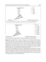
incidents into all causes and specific disabilities. Dorsopathies, arthropathies, and knee joint
disorders accounted for 21.2%, 10.5%, and 8.7% respectively, and occurred most frequently
at the site (Fig.4). Considering the priority of development and convenience of real
adaptation, we choose the knee assistive wearable system firstly not spine assist one.
Moreover, the working index of NIOSH recommends that construction workers’ spinal
columns should not be rapidly bent and their posture should be kept perpendicular to the
ground during manual construction work. That means a spine support system has to be
considered as support system not assist one. Therefore, this paper designed this specific part
of the body-knee joint of the type that partly assists the knee joint (Fig.5).
The following are the specifications of the system in this research:
• Occupational target: Construction worker
• Target region: Knees (The weight of the system is borne by the combined shank-ankle
orthotics)
• Target motions: Kneeling, lifting objects, and climbing a staircase or a slope
Fig. 5. Decision of Assistant Position Considering Two Dominant Causes of Disability of
Construction Workers
2.2 Definition of the target task
To specify the target tasks at a construction, we follow these process steps. First, we looked
at an overview of working patterns and types at construction sites. The overview was
sourced from NIOSH. In the second step, construction workers-especially the general
laborers-were classified into four major groups. As shown in step 2 under Fig.6, sheet metal
workers, electricians, laborers, and cement masons were put in charge of each group.
Finally, in the third step, based on the occupational common task of upper groups, target
Design and Feasibility Verification of a Knee Assistive Exoskeleton System
for Construction Workers
313
tasks were selected which included heavy material handling using knee, loaded level
walking, loaded ascent walking, and loaded descent walking.
As earlier mentioned, we developed a modular-type exoskeleton system to assist the lower
limb, and we applied this mechanism in a real construction site. Thus, the target mission to
handle heavy materials and loads at ground level and on a stairway, which is described in
the following images, is critically considered.
Fig. 6. Work group analysis for construction workers
3. Mechanics of muscle activity at the knee
3.1 Extensors of the knee
Rectus femoris functions as an extensor of knee extension, hip flexion, lateral rotation of the
hip, and abduction of the hip [12,13]. Regarding the effect of its weaknesses, direct
measurements of the contribution made by the rectus femoris to knee extension strength are
not available. However, the physiological cross-sectional area of the rectus femoris is
approximately 15% of the total quadriceps femoris muscle mass. Therefore, its negative
Robotics and Automation in Construction
314
effect on a knee is as much as this contribution [14]. Vastus intermedius functions as an
extensor of knee extension and prevents impingement of the pouch in the patellofemoral
joint. It is based on the physiological cross-sectional area range from approximately 15~40%
of the total muscle bulk [14]. Vastus lateralis is a large pinnate muscle, and its uncontested
action is knee extension. The amount of its recruitment is proportional to the amount of
resistance to extension [15]. If its activity is diminished, knee extension strength is reduced.
Its physiological cross-sectional area suggests that in some individuals, the vastus lateralis
may contribute 40% of the extension strength of the knee [16]. Vastus medialis is the most
studied among the four heads of the quadriceps femoris muscle [15]. It is divided into two
sections, VML (Longus) and VMO (Oblique), based on both anatomical and mechanical
analysis. It is approximately 20 to 35% of the overall cross-sectional area of quadriceps
femoris. It functions as an extensor of knee extension and for the stabilization of the patella
during knee extension [16,17,18].
Fig. 7. Primary Knee Extensors, Flexors, and Plantar Flexor Muscles Focused in this Study
3.2 Flexors of the knee
The hamstring muscles represent the primary flexors of the knee. Hamstrings comprise of
the biceps femoris longus and brevis, which form the lateral mass of the hamstrings, and the
semimembranosus and semitendinosus, which make up the medial mass. The major
functions of the hamstring are knee flexion, hip extension, medial rotation, lateral rotation of
the knee, medial rotation of the hip, lateral rotation of the hip, and adduction of the hip.
Hamstrings provide between 30 and 50% of hip extension strength and are active during
normal locomotion. The most prominent period of activity is during the transition between
the swing and stance periods of the gait cycle. During locomotion, the role of hamstrings’
Design and Feasibility Verification of a Knee Assistive Exoskeleton System
for Construction Workers
315
activity is to slow down the extension of the knee during late swing, and to help extend the
hip in the stance phase.
3.3 Mechanics of the two-joint muscles in the knee
The knee is controlled mostly by two-joint muscles that cross either the hip and knee, or the
knee and ankle. Contraction of one of these muscles alone produces movement in all of the
joints that the muscle crosses. To isolate movement at a single joint, the two-joint muscles
cross or they must contract with other muscles. The iliopsoas and the hamstrings, as an
example, together produce isolated knee flexion by canceling each other’s effect at the hip.
Similarly, simultaneous contraction of the gluteus maximus and quadriceps femoris
produces knee extension without hip flexion. However, the knee more frequently displays
simultaneous contraction of the quadriceps and hamstrings. This unusual pattern of
simultaneous contraction of two-joint muscles appears to increase the ability of the knee and
hip to generate the large moments needed during many activities [14].
4. System operation method – trial (1)
4.1 Angular displacement of the knee joint
Following the steps shown in the previous chapter, the final target task was defined more
specifically. We decided to devise a modular-type exoskeleton system for lower limb
assistance, that is, for handling heavy materials during level walks and on stairways. To
gather adequate motivation signals when the construction workers do their jobs at the site,
first, an analysis of knee joint movements was needed. Fundamentally, the muscle activation
status is completely different during level walks and on stairways. Figure.8 and Figure.9
show which parts of the muscle groups are mainly related to knee joint movement during
level walks. Thus, a different type of gait pattern is created for a dissimilar muscle activation
phase. In the case of the knee joint movement, three DOFs with angular rotations are
possible during the level walk.
The primary motion is knee flexion-extension with respect to a mediolateral axis. Knee
internal-external rotation and adduction-abduction (varus-valgus) also occur among healthy
individuals, but with less consistency and amplitude due to their soft tissue and bony
constraints to these motions. The information presented in this chapter was gathered from
the work of Spivak and Zuckerman (1998). The following table shows the range of normal
values of normal adult gaits at a free walking velocity. These values were used as reference
values while we performed the experiments.
Contents Values
Stride or cycle time 1.0 to 1.2 m/sec
Stride or cycle length 1.2 to 1.9 m
Step length 0.56 to 1.1 m
Step width 7.7 to 9.6 cm
Cadence 90 to 140 steps/min
Velocity 0.9 to 1.8 m/sec
Table 1. Range of Normal Values for the Time-Distance Parameters of Adult Gaits at a Free
Walking Velocity (Spivak and Zuckerman)
Robotics and Automation in Construction
316
Fig. 8. Phasic Pattern of the EMG Activity of the Muscle and the Angular Displacement of
the Knee during Level Walking by Healthy Adults
4.2 Extraction of the muscle activity pattern
During the stance phase, the quadriceps muscle group is relied on to control its tendency
towards knee flexion collapse with weight acceptance and single limb support. This muscle
group is activated during terminal swinging and then acts eccentrically during weight
acceptance, as the knee rotates from the fully extended position during the initial contact to
its peak support phase flexion of approximately 20 degrees during the loading response.
Thereafter, the quadriceps act concentrically to extend the knee through an early mid-stance,
as the body’s center of extremity mass is raised vertically over the supporting limb and the
anterior orientation of the ground reaction force vector precludes the need for further
muscular control of knee flexion. Most hamstring muscles are activated in the late mid-
swing or the terminal swing. Their function with respect to the knee is probably to control
the angular acceleration of the knee extension. The short head of the biceps femoris is
activated earlier and probably assists in flexing the knee for foot clearance.
Design and Feasibility Verification of a Knee Assistive Exoskeleton System
for Construction Workers
317
(a) Muscle Activity Pattern of Anterior Side of the Leg during Walking and Proposed Sensor
Position ‘1’
(b) Muscle Activity Pattern of Posterior Side of the Leg during Walking and Proposed
Sensor Position '2' and '3' (Position '2' is discarded finally)
Fig. 9. Muscle Activity Pattern of Leg and Proposed Sensor Position for Exoskeleton
The gracilis and sartorius muscles may also contribute to swing-phase knee flexion when
they are activated during late pre-swing, initial swing, and early mid-swing. These muscles,
however, may very well be acting as primary hip flexors during this period [19]. Based on
Fig.8, we analogize that to explain or measure the gait pattern using the muscle activity
pattern, we must consider three positions of the muscle groups.
In this study, however, we propose a method that uses only two muscle sensing groups.
Although this approach is not perfect, it reduced the MSS module in the proposed system
and minimized the loads in the processing system. We decided to disregard the sensor
position (2) because we could explain the muscle activity pattern during the entire cycle
using only (1) and (3). Fig.9 describes the sensor position of the anterior side (1) and the
posterior side (3) of the sensor position we chose. The gray areas represent activation below
20% of the maximum voluntary contraction, and black areas represent activation above 20%
of the maximum voluntary contraction. Muscle activation means Knee Assistive System
(KAS) is inflated at the moment when the foot of the user touches the ground; the