Báo cáo hóa học: "Localized-Surface-Plasmon Enhanced the 357 nm Forward Emission from ZnMgO Films Capped by Pt Nanoparticles" ppt
Bạn đang xem bản rút gọn của tài liệu. Xem và tải ngay bản đầy đủ của tài liệu tại đây (336.26 KB, 5 trang )
NANO EXPRESS
Localized-Surface-Plasmon Enhanced the 357 nm Forward
Emission from ZnMgO Films Capped by Pt Nanoparticles
J. B. You Æ X. W. Zhang Æ J. J. Dong Æ X. M. Song Æ Z. G. Yin Æ
N. F. Chen Æ H. Yan
Received: 15 April 2009 / Accepted: 26 May 2009 / Published online: 12 June 2009
Ó to the authors 2009
Abstract The Pt nanoparticles (NPs), which posses the
wider tunable localized-surface-plasmon (LSP) energy
varying from deep ultraviolet to visible region depending
on their morphology, were prepared by annealing Pt thin
films with different initial mass-thicknesses. A sixfold
enhancement of the 357 nm forward emission of ZnMgO
was observed after capping with Pt NPs, which is due to the
resonance coupling between the LSP of Pt NPs and the
band-gap emission of ZnMgO. The other factors affecting
the ultraviolet emission of ZnMgO, such as emission from
Pt itself and light multi-scattering at the interface, were
also discussed. These results indicate that Pt NPs can be
used to enhance the ultraviolet emission through the LSP
coupling for various wide band-gap semiconductors.
Keywords ZnMgO films Á Photoluminescence Á
Localized surface plasmon Á Nanoparticles
Introduction
Due to their wide band-gap and high exciton binding
energy, ZnO and its alloys are of considerable interest for
applications as optoelectronic devices, such as short-
wavelength light-emitting diode (LED) and laser diode
(LD). Especially, the band-gap of Zn
1-x
Mg
x
O alloys can
be tuned from 3.3 to 4.2 eV by Mg incorporation with
different contents, which suggests that Zn
1-x
Mg
x
O has
great potential for using as optoelectronic devices in deep
ultraviolet (UV) region [1–3]. High optical quality ZnMgO
thin films with the strong UV emission are necessary to
utilize the aforementioned good properties of ZnMgO.
Unfortunately, intrinsic defects of ZnMgO lead to a low
UV emission efficiency, which hinders its application in
light-emitting devices [1–3]. Therefore, how to control the
influence of defect states and improve UV emission effi-
ciency has become a major issue, and numerous studies
have been conducted with it.
Recently, a significant enhancement of ZnO UV emission
has been achieved by coating a continuous metal film on
ZnO via surface-plasmon-polarization (SPP) coupling [4,
5]. In most of previous reports, metal-film-capped emitter
structures were usually adopted, and light was emitted
through substrates into the free space. For this backward
geometry a transparent substrate is required, which restricts
its wide applications. More recently, Cheng et al. [6] and Lu
et al. [7] demonstrated that the enhancement of forward
emission from ZnO can be achieved by localized-surface-
plasmon (LSP) coupling through depositing Ag nanoparti-
cles (NPs) on ZnO surface. However, Ag NPs can only show
plasmon excitations at wavelengths longer than 400 nm,
thus the energy match is not ideal for the coupling between
Ag LSP and band-gap emission of ZnO (378 nm). In the
case of Zn
1-x
Mg
x
O, the coupling between Ag LSP and Zn
1-
x
Mg
x
O band-gap emission will become worse because of
even larger difference in energy [8–11]. Fortunately, the
LSP energy of Pt NPs can be tuned in a wide region from the
deep-UV to visible region [12, 13], which provides the
possibility of enhancing band-gap emission of Zn
1-x
Mg
x
O
J. B. You Á X. W. Zhang (&) Á J. J. Dong Á
Z. G. Yin Á N. F. Chen
Key Lab of Semiconductor Materials Science, Institute of
Semiconductors, CAS, 100083 Beijing, People’s Republic of
China
e-mail:
X. M. Song Á H. Yan
Lab of Thin Film Materials, College of Materials Science and
Engineering, Beijing University of Technology, 100022 Beijing,
People’s Republic of China
123
Nanoscale Res Lett (2009) 4:1121–1125
DOI 10.1007/s11671-009-9366-y
via Pt LSP coupling. In this study, we report on using LSP of
Pt NPs to enhance the band-gap emission of Zn
1-x
Mg
x
O. A
sixfold enhancement of the forward emission at 357 nm is
obtained by capping Pt NPs on Zn
1-x
Mg
x
O surface, indi-
cating that the Pt LSP coupling is a promising method for
improving UV emission of ZnO-based alloys.
Experimental Details
The ZnMgO films were deposited on Al
2
O
3
(001) substrates
by radio-frequency (RF) magnetron co-sputtering from ZnO
(99.99%) and MgO (99.99%) targets [14]. The target-sub-
strate distances are 8 and 12 cm for the ZnO and MgO tar-
gets, respectively. The sputtering chamber was evacuated to
a base pressure of 1.0 9 10
-5
Pa, and then filled with the
working gas to a pressure of 1.0 Pa. Prior to deposition, the
substrates were sequentially cleaned in the ultrasonic baths
of acetone, ethanol and de-ionized water, and then blown
dried with nitrogen gas. In this study, both RF powers
applied to the ZnO and MgO targets were kept at a constant
of 80 W, and sapphire substrates were held at 600 °C. To
improve the crystallinity, the ZnMgO films were annealed in
vacuum at 800 °C for 2 h. Finally, the Pt NPs were grown on
the ZnMgO surface by sputtering deposition of Pt thin films
followed by annealing. Annealing was performed by rapid
thermal annealing (RTA) in N
2
ambient at 800 °C for 3 min.
The sizes of Pt NPs were controlled by varying Pt mass-
thicknesses ranging from 2 to 8 nm.
The structures of the ZnO and ZnMgO films were
studied by X-ray diffraction (XRD) in h–2h mode with a
Bruker D8 diffractometer with a Cu Ka X-ray source. The
morphologies of Pt NPs on SiO
2
substrates were investi-
gated by a field emission scanning electron microscopy
(FE-SEM, Hitachi S4800). Photoluminescence (PL) spec-
tra were excited by using the 325 nm emission of He-Cd
laser with the power of 30 mW and taken at room tem-
perature (RT) by using a grating spectrometer and a pho-
tomultiplier tube (PMT) detector, and both excitation and
detection were carried on the top of the samples. The
optical transmittance and reflection spectra were measured
as a function of incident photon wavelength at wavelengths
between 200 and 800 nm from films deposited on the fused
silica substrates using a Shimadzu UV-3101 spectropho-
tometer. The spectrophotometer was used in a double-beam
mode with a bare substrate in the reference beam to obtain
transmittance data through the film alone.
Results and Discussion
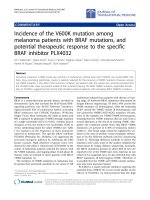
XRD patterns of the ZnO and ZnMgO films are shown in
Fig. 1. Besides the sapphire substrate diffraction peak
located at 41.7°, only (002) and (004) diffraction peaks of
ZnO at about 34.3° and 72.4° are observed for the ZnO
film, indicating that the ZnO thin film was grown along a c-
axis orientation of the sapphire substrate [11]. The ZnMgO
film exhibits a similar XRD pattern as the ZnO film,
inferring that a single phase of hexagonal ZnMgO was
obtained and it was also highly c-axis oriented. Further-
more, a slight shift of the (002) peak to large diffraction
angles is observed in an enlarged view of the ZnO and
ZnMgO (002) diffraction peaks, as presented in the inset of
Fig. 1, demonstrating the decrease of the c-axis length of
ZnO after Mg incorporation [15]. Based on the peak shift
and the lattice strain model [16, 17], the Mg content in
ZnMgO is estimated to be about 10%, demonstrating that
Mg atoms were successfully incorporated into ZnO lattice.
The absorption coefficient a can be calculated from the
transmittance and reflectance measurements. As a direct
band-gap semiconductor, the absorption coefficient a of
ZnO can be described as a = A(hm - E
g
)
1/2
. Thus, the
band-gap E
g
can be determined from the relation between a
and hm.Thea
2
as the function of incident photon energy hm
is plotted in Fig. 2 for the ZnO and ZnMgO films,
respectively. From the hm axis intercept of the linear part of
the plot a
2
versus hm, the optical band-gaps of the ZnO and
ZnMgO are determined to be 3.26 and 3.47 eV, respec-
tively, which indicates that the band-gap of ZnO has been
widen about 0.21 eV after 10% Mg incorporation.
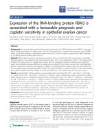
The Pt NPs were achieved by annealing the Pt films with
different mass-thicknesses ranging from 2 to 8 nm on SiO
2
substrates, and the corresponding SEM images are pre-
sented in Fig. 3. Due to the difference of the thermal
expansion coefficient between the substrates and Pt films,
when the initial thickness of Pt films is in the scale of
nanometers, the compressive stress induced by annealing
Fig. 1 XRD patterns of the ZnO and ZnMgO films on Al
2
O
3
(001)
substrates, and the inset shows an enlarged view of the ZnO and
ZnMgO (002) diffraction
1122 Nanoscale Res Lett (2009) 4:1121–1125
123
and the Ostwald ripening mechanism would cause the Pt
films to form isolated particles [18]. With increasing the Pt
mass-thickness from 2 to 8 nm, the particle size increases
from 20 to 200 nm, while the inter-particle distance of the
Pt NPs increases from 20 to 150 nm. It is also found that
the particle shape changes from sphericity to ellipse when
the Pt mass-thickness increases from 2 to 6 nm, and they
form a semi-continuous percolation film when the mass-
thickness exceeds 8 nm. Obviously, the size, distance and
shape of Pt NPs can be easily controlled by varying the
initial mass-thicknesses of the Pt films, which will be in
favor for tuning the characteristics of Pt LSP [18, 19].
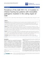
To determine the LSP resonance position of the Pt
NPs, the extinction spectra of the Pt NPs with mass-
thickness varying from 2 to 8 nm were measured and the
corresponding results are shown in Fig. 4. As seen from
Fig. 4, all the extinction spectra of the Pt NPs exhibit an
obvious extinction peak varying from sample to sample,
implying that the resonance position of LSP resonance
can be tuned [19]. For the Pt NPs with the mass-thick-
ness of 2 nm (particle size 20 nm), the resonance posi-
tion of LSP is observed at 250 nm, which falls in the
deep-UV region. Because retardation effects occur on the
particles due to their increasing diameter [12], the
extinction peak shifts toward larger wavelengths with
increasing particle size. Noteworthily, the resonance
position of LSP shifts to about 350 nm as the size of Pt
NPs increases to 100 nm (mass-thickness 6 nm), which is
close to the band-gap of ZnMgO, implying that the Pt
NPs with suitable size can be used to enhance the UV
emission of ZnMgO [4–11].
Room PL spectra of the ZnMgO films covered with
and without Pt NPs (mass-thickness: 6 nm, LSP reso-
nance position: 350 nm) are shown in Fig. 5. The ZnMgO
film shows a weak UV emission at 357 nm (3.47 eV), and
this energy is consistent with the band-gap of the ZnMgO
film obtained from Fig. 2, inferring the band-gap emission
from ZnMgO. The PL peak intensity of the reference
ZnMgO at 357 nm is normalized to one, and a sixfold
enhancement in peak PL intensity is observed from the
ZnMgO film capped with the Pt NPs. Previous theoretical
work demonstrated that the PL behavior also existed in
Fig. 2 The relationship between the square of absorption coefficient
(a
2
) and photo energy (hm) for the ZnO and ZnMgO films
Fig. 3 SEM images of the Pt
NPs with the different initial
mass-thicknesses of (a) 2 nm,
(b) 4 nm, (c) 6 nm, and (d)
8 nm on SiO
2
substrates
Nanoscale Res Lett (2009) 4:1121–1125 1123
123
noble metals due to direct recombination of the conduc-
tion-band electrons near the Fermi level with the holes in
the d band [20]. To exclude the possibility of the
enhanced emission from Pt NPs themselves, the PL
spectrum of the counterpart Pt NPs is also shown in
Fig. 5. Although the weak PL signal from Pt NPs was
observed by Kang et al. with a micron-PL spectra [18], no
observable PL signal was detected in our experiment.
Thus, the contribution of Pt NPs themselves to the UV
emission of the Pt/ ZnMgO film can be safely excluded.
Another possible explanation for the PL enhancement
factor would be an increase in extraction angle, since
capping metal particles on an emitter surface may lead to
light multi-scattering at the metal/emitter interface. To
check this mechanism, the PL spectrum of the ZnMgO film
capped by Ag NPs is also given in Fig. 5. Here, the Ag NPs
with the similar morphology as the Pt NPs were prepared
by annealing a 6 nm Ag layer deposited on a reference
ZnMgO film. In Fig. 5, only about a 1.1-fold enhancement
in peak PL intensity is observed from the Ag-capped
ZnMgO film. Actually, from Fig. 4 one can see that the
main extinction peak of Ag NPs on SiO
2
substrate is
located at 530 nm, which is far from the band-gap of
ZnMgO (3.47 eV, 357 nm), and a minor peak at 360 nm as
quadrupole extinction is a second-order effect [12]. Thus,
the resonance coupling between the Ag LSP and the band-
gap emission of ZnMgO can be ignored safely [4–11], and
the observed slight enhancement of PL intensity for the
Ag-capped ZnMgO in Fig. 5 can be ascribed to a simple
multi-scattering of light that occurred at the Ag/ZnMgO
interface. Because of the similar morphology between the
Ag and Pt NPs, for the Pt-capped ZnMgO film an emission
enhancement resulting from multi-scattering is expected to
be weaker also, e.g., *1.1-fold. Therefore, the multi-
scattering mechanism cannot explain the observed sixfold
enhancement alone, and the larger enhancement of the UV
emission from the Pt-capped ZnMgO film mainly be
attributed to the resonance coupling between the Pt LSP
and the band-gap emission of ZnMgO. This LSP-enhanced
emission process can be described as follows. When the
LSP energy of Pt NPs is matched with the band-gap of
ZnMgO, the excitation of LSP is much faster than other
recombination processes in ZnMgO because of the high
density of states induced by LSP resonance. Consequently,
most of the energy of excited states in ZnMgO is trans-
ferred into LSP [4–11]. After that, LSP can be scattered as
a far field radiation by the Pt NPs [6, 7, 21]. Since the
increase of scattering cross-section with particle size is
much more significant than absorption cross-section, the
particles with larger sizes will be favor to convert LSP into
light [21]. In fact, a sixfold enhancement of the ZnMgO
band-gap emission was obtained by the LSP coupling using
the Pt NPs with the size of 100 nm.
Theoretically, the enhancement factor F
p
(Purcell fac-
tor) up to 10
3
orders of magnitude can be achieved when
the SP energy of metal is well consistent with the excited
states of emitters [22]. However, only a sixfold enhance-
ment of the band-gap emission of ZnMgO was observed in
the present work. We propose that the achievement of the
high enhancement ratio is restricted by the following fac-
tors. Firstly, a downward-going radiation cannot be pre-
vented, leading to the energy loss of LSP [23]. Secondly,
the broad extinction peak of the Pt NPs is unfavored for the
LSP coupling [24]. Thirdly, since the Pt NPs have stronger
extinction ability at 325 nm as seen from Fig. 4, the power
of the excited laser dissipates partly on the surface of Pt/
ZnMgO, which results in the less excited states in Pt/
ZnMgO than the reference ZnMgO. Besides, several other
Fig. 4 Extinction spectra of the Pt NPs with the different initial
mass-thicknesses varying from 2 to 8 nm on SiO
2
substrates. For
comparison, the extinction spectrum of the Ag NPs with the similar
morphology as Pt on SiO
2
substrates is also included
Fig. 5 Room temperature PL spectra of the ZnMgO, Pt/ZnMgO, Ag/
ZnMgO, and Pt NPs
1124 Nanoscale Res Lett (2009) 4:1121–1125
123
factors, such as the Ohmic loss [25], non-radiative Forster
energy transfer [5], lower SP radiative efficiency [21], may
be responsible for the weakened enhancement. And also,
for the three-layered structure (Pt/ZnMgO/Al
2
O
3
), power
lost to the substrate waveguide mode may also be one of
the reasons of the weakened enhancement [26]. Actually,
in recent reports, two to seven fold enhancements were
usually attained by SP coupling [6, 7, 9, 27], except for few
experiment results with enhancement ratios beyond tenfold
[8, 10]. Noticeably, in our case, the enhancement ratio can
be further improved by optimizing the process conditions.
For example, the extinction peak can become narrower by
controlling the uniformity and the mono-dispersion of Pt
NPs [12]. Additionally, the loss from the dissipation of the
excited laser can be eliminated automatically for the LSP-
enhanced electroluminescence in which the excited states
are induced by electron injection.
Conclusions
In conclusion, the Pt NPs with different morphologies,
corresponding to the LSP resonance position varying from
deep-UV to visible region, have been prepared by
annealing Pt thin films with various mass-thicknesses. The
357 nm forward emission of the ZnMgO film capped with
the Pt NPs is enhanced by sixfold via the coupling between
the Pt LSP and the band-gap emission of ZnMgO. Though
the enhancement ratio is far away from the theoretical
value, it would be very significant if a sixfold UV emission
enhancement can be attained for a practical optical-elec-
trical device. These results show that Pt NPs can be used to
enhance the UV emission through the LSP coupling for
various wide band-gap semiconductors, such as ZnMgO,
AlN, AlGaN and so on.
Acknowledgments This work was financially supported by the
National Natural Science Foundation of China (Grant No. 50601025,
60876031) and the ‘‘863’’ project of China (2009AA03Z305). One of
the authors (JBY) thanks the CAS Special Grant for Postgraduate
Research, Innovation and Practice.
References
1. U. Ozgur, Y.I. Alivov, C. Liu, A. Teke, M.A. Reshchikov, S.
Dogan, V. Avrutin, S.J. Cho, H. Morkoc, J. Appl. Phys. 98,
041301 (2005)
2. D.K. Hwang, M.S. Oh, J.H. Lim, S.J. Park, J. Phys. D: Appl.
Phys. 40, R387 (2007)
3. H. Tampo, H. Shibata, K. Maejima, A. Yamada, K. Matsubara, P.
Fons, S. Niki, T. Tainaka, Y. Chiba, H. Kanie, Appl. Phys. Lett.
91, 261907 (2007)
4. C.W. Lai, J. An, H.C. Ong, Appl. Phys. Lett. 86, 251105 (2005)
5. W.H. Ni, J. An, C.W. Lai, H.C. Ong, J.B. Xu, J. Appl. Phys. 100,
026103 (2006)
6. P.H. Cheng, D.S. Li, Z.Z. Yuan, P.L. Chen, D.R. Yang, Appl.
Phys. Lett. 92, 041119 (2008)
7. H.F. Lu, X.L. Xu, L. Lu, M.G. Gong, Y.S. Liu, J. Phys.: Condens.
Matter 20, 472202 (2008)
8. K. Okamoto, I. Niki, A. Shvartser, Y. Narukawa, T. Mukai, A.
Scherer, Nat. Mater. 3, 601 (2004)
9. Y.C. Lu, C.Y. Chen, K.C. Shen, D.M. Yeh, T.Y. Tang, C.C.
Yang, Appl. Phys. Lett. 91, 183107 (2007)
10. P.P. Pompa, L. Martiradonna, A. Della Torre, F. Della Sala, L.
Manna, M. De Vittorio, F. Calabi, R. Cingolani, R. Rinaldi, Nat.
Nanotechnol. 1, 126 (2006)
11. J.B. You, X.W. Zhang, Y.M. Fan, S. Qu, N.F. Chen, Appl. Phys.
Lett. 91, 231907 (2007)
12. C. Langhammer, Z. Yuan, I. Zoric, B. Kasemo, Nano Lett. 6, 833
(2006)
13. N.C. Bigall, T. Hartling, M. Klose, P. Simon, L.M. Eng, A.
Eychmuller, Nano Lett. 8, 4588 (2008)
14. T. Minemoto, T. Negami, S. Nishiwaki, H. Takakura, Y.
Hamakawa, Thin Solid Films 372, 173 (2000)
15. P. Wang, N.F. Chen, Z.G. Yin, R.X. Dai, Y.M. Bai, Appl. Phys.
Lett. 89, 202102 (2006)
16. N.F. Chen, Y.T. Wang, H.J. He, L.Y. Lin, Phys. Rev. B 54, 8516
(1998)
17. A.B.M.A. Ashrafi, Y. Segawa, J. Vac. Sci. Technol. B 23, 2030
(2005)
18. C.Y. Kang, C.H. Chao, S.C. Shiu, L.J. Chou, M.T. Chang, G.R.
Lin, C.F. Lin, J. Appl. Phys. 102, 073508 (2007)
19. S. Pillai, K.R. Catchpole, T. Trupke, M.A. Green, J. Appl. Phys.
101, 093105 (2007)
20. A. Mooradian, Phys. Rev. Lett. 22, 185 (1969)
21. J.R. Lakowicz, Anal. Biochem. 337, 171 (2005)
22. A. Neogi, C.W. Lee, H.O. Everitt, T. Kuroda, A. Tackeuchi, E.
Yablonvitch, Phys. Rev. B 66, 153305 (2002)
23. W.L. Barnes, J. Lightwave Technol. 17, 2170 (1999)
24. J.B. Khurgin, G. Sun, R.A. Soref, Appl. Phys. Lett. 93, 021120
(2008)
25. D.M. Yeh, C.F. Huang, Y.C. Lu, C.Y. Chen, T.Y. Tang, J.J.
Huang, K.C. Shen, Y.J. Yang, C.C. Yang, Appl. Phys. Lett. 91,
063121 (2007)
26. P.H. Cheng, D.S. Li, D.R. Yang, Opt. Express 16, 8896 (2008)
27. M.K. Kown, J.Y. Kim, B.H. Kim, I.K. Park, C.Y. Cho, C.C.
Byeon, S.J. Park, Adv. Mater. 20, 1253 (2008)
Nanoscale Res Lett (2009) 4:1121–1125 1125
123