Báo cáo hóa học: "Research Article Low-Complexity Estimation of CFO and Frequency Independent I/Q Mismatch for OFDM Systems" pdf
Bạn đang xem bản rút gọn của tài liệu. Xem và tải ngay bản đầy đủ của tài liệu tại đây (837.86 KB, 11 trang )
Hindawi Publishing Corporation
EURASIP Journal on Wireless Communications and Networking
Volume 2009, Article ID 542187, 11 pages
doi:10.1155/2009/542187
Research Article
Low-Complexity Estimation of CFO and Frequency Independent
I/Q Mismatch for OFDM Systems
Ying Chen,
1, 2
Jian (Andrew) Zhang,
1, 2
andA.D.S.Jayalath
3
1
Department of Information Engineering, The Australian National University, Canberra, ACT 0200, Australia
2
Program of Networked Systems, National ICT Australia (NICTA), Canberra, ACT 2601, Australia
3
School of Engineering Systems, Queensland University of Technology, Queensland, QLD 4001, Australia
Correspondence should be addressed to Ying Chen,
Received 1 November 2008; Revised 20 February 2009; Accepted 27 April 2009
Recommended by Marc Moonen
CFO and I/Q mismatch could cause significant performance degradation to OFDM systems. Their estimation and compensation
are generally difficult as they are entangled in the received signal. In this paper, we propose some low-complexity estimation
and compensation schemes in the receiver, which are robust to various CFO and I/Q mismatch values although the performance
is slightly degraded for very small CFO. These schemes consist of three steps: forming a cosine estimator free of I/Q mismatch
interference, estimating I/Q mismatch using the estimated cosine value, and forming a sine estimator using samples after I/Q
mismatch compensation. These estimators are based on the perception that an estimate of cosine serves much better as the basis
for I/Q mismatch estimation than the estimate of CFO derived from the cosine function. Simulation results show that the proposed
schemes can improve system performance significantly, and they are robust to CFO and I/Q mismatch.
Copyright © 2009 Ying Chen et al. This is an open access article distributed under the Creative Commons Attribution License,
which permits unrestricted use, distribution, and reproduction in any medium, provided the original work is properly cited.
1. Introduction
Orthogonal Frequency Division Multiplexing (OFDM)
becomes the foundation technique for broadband wireless
communications because of its various advantages including
high spectrum efficiency, low complexity equalization and
great flexibility in resource optimization. However, one well-
known disadvantage of OFDM is its high sensitivity to carrier
frequency offset (CFO) [1]. CFO refers to the frequency
difference between the local oscillators in the transmitter
and receiver. CFO causes intercarrier interference (ICI) and
could deteriorate the system performance seriously. CFO
itself is not difficult to estimate and compensate, using either
training-based or blind estimation schemes [2, 3]. However,
when some distortions, in particular, I/Q mismatch, are
entangled with CFO, the performance of conventional CFO
estimator will degrade significantly [4].
I/Q mismatch is caused by the imbalance between
the components of the Inphase (I-) and Quadrature (Q-)
branches in I/Q modulated systems. I/Q mismatch includes
gain and phase mismatches. Gain mismatch is caused by the
gain difference of amplifiers or filters in I- and Q- branches.
Phase mismatch is caused by the nonideal π/2rotationin
local oscillators and the phase difference between analogue
filters in I- and Q- branches. In a practical receiver with
analog I/Q separation, I/Q mismatch always exists and con-
tributes as interference in general CFO estimation. On the
other hand, without the knowledge of CFO, a training-based
estimator cannot estimate I/Q mismatch accurately. CFO
estimation in the presence of I/Q mismatch is not trivial,
and has been investigated in, for example, [5–14]. Each of
these schemes partially solves the CFO estimation problem
in the presence of I/Q mismatch, with respective drawbacks.
In [5, 6], initial CFO is estimated in the presence of errors
caused by I/Q imbalance. Then, based on the CFO estimates,
[5] proposes an iterative I/Q mismatch estimation approach,
which requires five iterations to obtain the gain parameter. In
[6], a simple time domain I/Q mismatch estimation method
is proposed, but the performance degrades significantly
whenCFOissmall.[6] also proposes a frequency domain
estimator which improves performance when CFO is small,
however, it is sensitive to transmitter side mismatch. In [7],
an iterative scheme is proposed, requiring special training
symbols which contain many zeros to suppress the I/Q
2 EURASIP Journal on Wireless Communications and Networking
mismatch effect in the receiver. In [8], a searching-based CFO
estimator is developed. The high computational complexity,
however, may prevent it from practical applications. In [12]
iterative estimators are proposed, and they have relatively
high complexity. In [13], a frequency domain adaptive
I/Q mismatch compensation scheme is proposed, however,
it requires perfect CFO knowledge. In [14], perfect CFO
knowledge is required either in the training based RLS
method or in forming the per-tone-equalizer. In [9, 10],
CFO estimators based on three identical training symbols
are proposed. However, [9] only uses a cosine function of
the CFO to estimate the CFO parameter. The scheme is thus
very sensitive to noise when CFO and/or I/Q mismatch is
small, and has a phase ambiguity problem with positive and
negative phases. Improvement to [9]ismadein[10], using
two groups of three identical training symbols. Although
this estimator is robust to both transmitter and receiver I/Q
mismatch, the special long training symbols designed for
CFO estimation increase system overhead and are incom-
patible with current standards. In [11], a complete CFO
and I/Q mismatch estimation and compensation scheme
is proposed based on the CFO estimator in [9]. However,
I/Q mismatch parameters are estimated based on the CFO
estimates, which is sensitive to noise, particularly when CFO
is small.
In our early work [15], we independently developed a
CFO estimation scheme partially similar to the approach
in [10]. Different to [10], our scheme only requires one
group of three identical training symbols by forming an
approximated estimator for the CFO. The scheme works well
for various I/Q mismatch values when the CFO is not too
small (say, 10% of the normalized CFO), and the perfor-
mance otherwise degrades. In this paper, we propose some
novel estimation schemes which are robust to any values of
both transmitter and receiver I/Q mismatch, and have better
accuracy of the I/Q mismatch estimation for small CFO.
The schemes use a group of at least three identical training
symbols, which are generally present in the preamble of
current systems, for example, WLAN and WiMAX systems.
They serially estimate I/Q mismatch and CFO with low
complexity, without incurring iterative process. The schemes
mainly consist of three steps. Firstly, a cosine function of
the CFO, which is free of I/Q mismatch interference, is
formed using a group of three identical training symbols.
Secondly, based on the estimated value of the cosine function
instead of the CFO estimate, the I/Q mismatch parameters
are estimated. Thirdly, the I/Q mismatch is compensated
using the estimates, and a sine function of the CFO is formed
based on the compensated signal. Combining the results
of cosine and sine functions, CFO can then be estimated
accurately. The use of cosine value instead of the CFO
estimate for I/Q mismatch estimation is from the insight
that the cosine value is much more robust to noise than
the CFO estimate. The rest of the paper is organized as
follows. Section 2 formulates the problem of CFO and I/Q
mismatch estimation in OFDM systems. In Section 3, the
proposed CFO and I/Q mismatch estimation schemes are
developed. Simulation results are presented in Section 4.
Section 5 concludes the paper.
2. Problem Formulation and System Structure
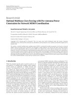
An OFDM system model with CFO and I/Q mismatch
estimation and compensation is shown in Figure 1.Let
transmitter’s gain mismatch be η and phase mismatch be γ.
Denoting the baseband signal as s(t)
= s
I
(t)+js
Q
(t), the
analog signal radiated from the transmitter antenna (denoted
as RF signal hereafter) can be represented as
˘
s
(
t
)
=
1+η
s
I
(
t
)
cos
ω
c
t + γ
−
1 −η
s
Q
(
t
)
sin
ω
c
t − γ
,
(1)
where ω
c
is the carrier frequency. The received RF signal
˘
r(t)
becomes
˘
r
(
t
)
=
˘
s
(
t
)
⊗h
(
t
)
+ ξ
(
t
)
,(2)
where h(t) is the channel impulse response, ξ(t) is additive
white Gaussian Noise (AWGN), and
⊗ denotes the linear
convolution. The signal is down-converted to baseband by
an oscillator with imbalanced inphase input (1+ε)cos(ω
c
t −
ω
d
t − θ) and quadrature input (1 − ε) sin(ω
c
t − ω
d
t +
θ), where ε and θ represent gain and phase mismatch in
the receiver, respectively, and ω
d
is the frequency offset
between the transmitter and receiver oscillators. The received
signal is then filtered by a Low Pass Filter (LPF). The
filtered signal is sampled at a sampling rate f
s
= 1/T
s
,
where T
s
is the sampling period. The sampled baseband
signal, consisted of signals in I- and Q- branches, can be
represented as
y
(
n
)
= y
I
(
n
)
+ jy
Q
(
n
)
,(3)
where
y
I
(
n
)
= ξ
I
(
n
)
+
(
1+ε
)
2
cos
(
ω
d
n + θ
)
×
1+η
r
I
(
n
)
cos γ
−
1 −η
r
Q
(
n
)
sin γ
−
(
1+ε
)
2
sin
(
ω
d
n + θ
)
×
−
1+η
r
I
(
n
)
sin γ +
1 −η
r
Q
(
n
)
cos γ
,
y
Q
(
n
)
= ξ
Q
(
n
)
+
(
1
−ε
)
2
cos
(
ω
d
n −θ
)
×
−
1+η
r
I
(
n
)
sin γ +
1 −η
r
Q
(
n
)
cos γ
+
(
1
−ε
)
2
sin
ω
d
n −γ
×
1+η
r
I
(
n
)
cos γ
−
1 −η
r
Q
(
n
)
sin γ
.
(4)
The r
I
(n)andr
Q
(n)in(4) are the sampled real and imaginary
outputs of the convolution between s(t) and the baseband
EURASIP Journal on Wireless Communications and Networking 3
channel impulse response, respectively, ξ
I
(n)andξ
Q
(n)are
the noise in I- and Q- branches, respectively. Define
x
I
(
n
)
1
2
1+η
r
I
(
n
)
cos γ
−
1 −η
r
Q
(
n
)
sin γ
,
x
Q
(
n
)
1
2
−
1+η
r
I
(
n
)
sin γ +
1 −η
r
Q
(
n
)
cos γ
.
(5)
Equation (4)canberewrittenas
y
I
(
n
)
= g
1
x
I
(
n
)
cos
φ
n
+ θ
−
x
Q
(
n
)
sin
φ
n
+ θ
+ ξ
I
(
n
)
= g
1
cos
(
θ
)
x
I
(
n
)
cos φ
n
−x
Q
(
n
)
sin φ
n
−
sin
(
θ
)
x
I
(
n
)
sin φ
n
+ x
Q
(
n
)
cos φ
n
+ ξ
I
(
n
)
,
y
Q
(
n
)
= g
2
x
I
(
n
)
sin
φ
n
−θ
+ x
Q
(
n
)
cos
φ
n
−θ
+ ξ
Q
(
n
)
= g
2
cos
(
θ
)
x
I
(
n
)
sin φ
n
+ x
Q
(
n
)
cos φ
n
−
sin
(
θ
)
x
I
(
n
)
cos φ
n
−x
Q
(
n
)
sin φ
n
+ ξ
Q
(
n
)
,
(6)
where
φ
n
= ω
d
n, g
1
= 1+ε, g
2
= 1 − ε. (7)
Equation (6) shows that the transmitter side and the
receiver side I/Q mismatch impacts can be decoupled and
the transmitter side I/Q mismatch is only contained in x
I
(n)
and x
Q
(n). If the channel is static during CFO estimation,
periodically transmitted training symbols lead to periodical
x
I
(n)andx
Q
(n) at the receiver. In the CFO and I/Q mismatch
estimation algorithms to be presented, only the periodicity
of the baseband signal is required and exploited, and the
detailed information of x
I
(n)andx
Q
(n)isnotrequired.After
the CFO and receiver side I/Q mismatch are compensated,
the transmitter-side I/Q mismatch can be estimated via joint
estimation of channel and I/Q mismatch proposed in [6]or
by a least square estimator. In the following, we propose some
CFO and I/Q mismatch joint estimators, which only require
the periodicity of training sequences instead of the actual
signal values.
The complex signal in (3) can also be written as
y
(
n
)
= αx
(
n
)
e
jω
d
n
+ βx
∗
(
n
)
e
−jω
d
n
+ ξ
(
n
)
,(8)
where
x
(
n
)
= x
I
(
n
)
+ jx
Q
(
n
)
,
α
= cos
(
θ
)
+ jεsin
(
θ
)
,
β
= ε cos
(
θ
)
− j sin
(
θ
)
,
(9)
and the superscript “
∗
” denotes the conjugate.
According to (8), the received signal becomes the sum
of the scaled original signal and the interference from its
own conjugation. It is clear that CFO is always entangled
with I/Q mismatch. Even when CFO is known, without the
information of I/Q mismatch, the second part in (8) cannot
be eliminated, so CFO cannot be compensated correctly.
Thus it is a natural task to estimate CFO and I/Q mismatch
jointly.
3. CFO and I/Q Mismatch Estimation
Referring to Figure 1, the proposed scheme consists of three
steps, including forming a cosine estimator for CFO which is
free of I/Q mismatch interference, estimating I/Q mismatch
using the estimated cosine value, and forming a sine
estimator for CFO by removing I/Q mismatch in the received
signal using the estimated I/Q mismatch parameters. The
CFO is then estimated by combining the sine and cosine
estimator. In the process, both CFO and I/Q mismatch are
estimated in the presence of minimum interference from
each other, introduced by the residual estimation error due
to the noise.
3.1. Cosine Estimator Free of I/Q Mismatch Interference.
Denote the number of samples in each training symbol as
L
p
, and let φ = ω
d
L
p
.From(6), in I- branch, we have
y
I
n +2L
p
+ y
I
(
n
)
= 2g
1
cos φ
x
I
(
n
)
cos
φ
n
+ θ + φ
−x
Q
(
n
)
sin
φ
n
+ θ + φ
+ ξ
I
(
n
)
+ ξ
I
n +2L
p
=
2cosφ
y
I
n + L
p
−
ξ
I
n + L
p
+ ξ
I
(
n
)
+ ξ
I
n +2L
p
,
(10)
where the sum and difference formulas of sine and cosine
functions are used.
Then cos φ can be estimated by
cosφ
n
=
y
I
n +2L
p
+ y
I
(
n
)
2y
I
n + L
p
. (11)
To reduce the noise effect, final estimate needs to be averaged
over a number of samples. The general approach is to use
a maximal ratio combining (MRC). Denote the number of
total samples in the training sequence as N
L
.ForI-branch,
the estimate of cos φ basedonMRCisgivenby
cosφ =
N
L
−2L
p
n=1
y
I
n + L
p
y
I
n +2L
p
+ y
I
(
n
)
2
N
L
n=1
y
I
n + L
p
2
.
(12)
The formulation of (12) is similar to [10], where the
estimator is derived based on mixed signals from I/Q
branches. As an alternative to the MRC approach we propose
a lower complexity combiner. For I-branch, the estimator is
given by
4 EURASIP Journal on Wireless Communications and Networking
Proposed joint estimation
Compensation
LPFLPF
Mismatch
estimator
Other baseband
processing
cos(ω
c
t − ω
d
t − θ)
˘
r
(t)
w(t)
Channel
h(t)
˘
s(t)
(1 + η)
s
I
(t)
cos(ω
c
t − γ)
π/2+2γ
s
Q
(t)(1 −η)
(1 + ε)(1
−ε)
π/2+2θ
y
Q
(n) y
I
(n)
cos
φ estimator
sin
φ estimator
x
I
(n)
x
Q
(n)
Figure 1: Block diagram of an OFDM system showing CFO and I/Q mismatch, and the proposed estimators.
00.20.40.60.81
Normalised CFO
10
−5
10
−4
10
−3
10
−2
MSE of cosφ and φ estimates
cos φ
φ
Figure 2: Mean square error of the estimates for cosφ and φ versus
normalized CFO, where SNR
= 22 dB.
cosφ =
N
L
−2L
p
n=1
sign
y
I
n + L
p
y
I
n +2L
p
+ y
I
(
n
)
2
N
L
n=1
y
I
n + L
p
,
(13)
where sign(x)
= x/|x| for real x
/
=0 and sign(0) = 0. The
combiner is similar to an equal gain combiner (EGC), with
the function sign(x) ensuring samples to be combined in
a constructive way. This combiner, which will be called as
EGC hereafter, only requires one division, plus 2(N
L
− 2L
p
)
additions.
The EGC estimator even promises better performance
than MRC when the number of training symbols is large and
the CFO is small. The reason is that the MRC is the best one
only when (1) signal and noise are independent and (2) noise
samples are uncorrelated. However, when more than three
training symbols are used in averaging, each noise samples
could appear several times in combining. These repeated
noise samples are scaled by
−cos φ, and in EGC, some of the
items have opposite phases and a noise cancellation effect can
be achieved when cos φ approaches 1. Thus the total noise
can be partially cancelled due to the noise correlation in the
EGC estimator when cos φ is approaching 1.
For Q-branch, we can form a similar estimator. By
combining I- and Q- branches, the final cosine estimator
using EGC is given by (14)
cosφ =
N
L
−2L
p
n=1
sign
y
I
n + L
p
y
I
n +2L
p
+ y
I
(
n
)
+sign
y
Q
n + L
p
y
Q
n +2L
p
+ y
Q
(
n
)
2
N
L
−2L
p
n=1
y
I
n + L
p
+
y
Q
n + L
p
. (14)
EURASIP Journal on Wireless Communications and Networking 5
Imbalance estimator
Sine estimator
Cosine estimator
CFO estimator
Other baseband
processing
Compensation
Multipliers
Delay
Accumulators
Accumulators
y
Q
(n) y
I
(n)
x
I
(n)
x
Q
(n)
Figure 3: Implementation structure of the proposed estimators.
The corresponding CFO estimate is given by
ω
d
=
arccos
cosφ
L
p
. (15)
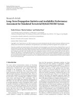
There are two problems with this estimator though it is
robust to I/Q mismatch. One is the phase ambiguity problem
as the range for φ in the estimator needs to be limited to
[0, π]. The other is, when φ is small, the estimation error
of φ increases rapidly even with cos φ varying slightly. This
is because the gradient of cos φ is large in this case. The
effect can be observed from Figure 2, where the variances
of the estimation errors for
cosφ and
φ obtained from
cos φ are plotted against the normalized CFO. The results
are obtained by using the general CFO estimation scheme
in (14) in an IEEE802.11a system without introducing I/Q
mismatch.
To eliminate the phase ambiguity and reduce the esti-
mation error for small φ, a complementary sine estimator is
generally needed. Such a sine estimator free of I/Q mismatch
cannot be constructed directly. In [10],asineestimator
is proposed based on special training symbols, which are
created by taking the original training sequences and super-
imposing an artificial CFO to generate point-wise 90-degree
phase rotation. In [15], we introduce an approximated sine
estimator, which can work without changing the training
symbols for the cosine estimator. However the estimator in
[15] sees interference from I/Q mismatch, particularly when
the mismatch is large. It is thus natural to consider the
approach of forming a sine estimator free of I/Q mismatch
after estimating and compensating it.
3.2. Estimation of I/Q Mismatch Parameters. As can be seen
from Figure 2, when φ is small, the estimate of cos φ is much
more robust to noise than φ. Next we develop an algorithm to
estimate the I/Q mismatch parameters based on the estimate
of cos φ instead of φ. This approach can estimate mismatch
parameters more accurately, particularly when φ is small.
From (8), the I/Q mismatch can be compensated as
x
(
n
)
e
jω
d
n
=
α
∗
y
(
n
)
−βy
∗
(
n
)
|α|
2
−
β
2
=
α
∗
|α|
2
−
β
2
y
(
n
)
−β
α
∗
y
∗
(
n
)
.
(16)
Since I/Q mismatch is generally fixed during one transmis-
sion, α
∗
/(|α|
2
−|β|
2
) is a fixed constant, and it will not
contribute to the CFO estimation and can be absorbed in
channel coefficients for I/Q mismatch compensation. Thus
we only need to know β/α
∗
to compensate the I/Q mismatch
for the moment. The value of β/α
∗
canbecomputedvia
μ αβ/(
|α|
2
+ |β|
2
), which can be estimated from cosφ.
The formulation of estimating μ from cos φ is shown in the
appendix, and the result is given by
μ =
N
L
−L
p
n=1
y
2
(
n
)
+ y
2
n + L
p
−
2y
(
n
)
y
n + L
p
cos φ
2
N
L
−L
p
n=1
y(n + L
p
)
2
+
y(n)
2
−2R
y
n + L
p
y
∗
(
n
)
cos φ
, (17)
6 EURASIP Journal on Wireless Communications and Networking
where R(x) denotes the real part of x.
From the estimate
μ, β/α
∗
can be computed by finding
its phase and magnitude separately. The phase of β/α
∗
is
obtained by
∠
β
α
∗
=
∠
|
α|
2
β
α
∗
=
∠
αβ
=
∠μ. (18)
To find the magnitude of β/α
∗
,weuse
1
μ
=
|
α|
2
+
β
2
αβ
=
α
∗
β
+
β
α
∗
.
(19)
Solving the equation, we get
β
α
∗
=
1 −
1 −4
μ
2
2
μ
. (20)
Note that we have dropped another solution which is
impractically large. Since
|μ| < |β/α| and in general systems
the I/Q mismatch is not very large, we have
|μ|1.
Applying Taylor series to (20), the amplitude of μ can be
approximated by
β
α
∗
≈
μ
−
1
4
μ
3
. (21)
Thus the estimate of β/α
∗
can be calculated as
β
α
∗
= e
j∠μ
μ
−
1
4
μ
3
,withμ obtained from
(
17
)
.
(22)
As pointed out in the appendix, the estimation accuracy
of μ becomes low when CFO is small and sin φ is approaching
zero. This is the common drawback of general I/Q mismatch
estimation schemes based on the periodicity of the training
sequence. To improve the performance of the proposed
schemes, further processing can be applied. For example,
a threshold can be set to initiate a frequency domain least
square estimator or a joint estimator for I/Q mismatch and
channel response [6] when the estimated CFO from cos φ is
smaller than the threshold. This threshold can be set as 0.1
according to our simulation results. The detailed discussion
is beyond the scope of this paper.
3.3. CFO Estimation after I/Q Mismatch Compensation.
3.3.1. Autocorrelation-Based CFO Estimation. When I/Q
mismatch parameters are known, a general approach is to
compensate the signal in time domain, and then apply
conventional autocorrelation-based CFO estimation given in
[3]. With estimated β/α
∗
given in (22), I/Q mismatch can be
compensated via (16), generating samples
x
c
(
n
)
x
(
n
)
e
jω
d
n
. (23)
An autocorrelation-based CFO estimator can then be
applied to the compensated samples, generating CFO esti-
mates
ω
d
=
1
L
p
∠
⎛
⎝
N
L
+L
p
n=1
x
c
(
n
)
x
∗
c
n + L
p
⎞
⎠
. (24)
The performance of this estimator depends on the accuracy
of the estimated I/Q mismatch parameters.
3.3.2. Sine Estimator. The estimator given by (24) depends
on the estimation of I/Q mismatch, and estimation error
of I/Q mismatch affects both the cos and sin parts of the
CFO estimate. Alternatively, we can form a complementary
sine estimator to exploit the cosine estimator developed in
Section 3.1 whichisfreeofI/Qmismatch.Withestimated
I/Q mismatch parameters, a sine estimator can be formed as
follows.
It is easy to verify that
R
x
c
n +2L
p
−
x
c
(
n
)
=−
2I
x
c
n + L
p
sin φ
I
x
c
n +2L
p
−
x
c
(
n
)
=
2R
x
c
n + L
p
sin φ,
(25)
where I(x) denotes the imaginary part of x.Thensinφ can
be estimated as
sinφ =
R
x
c
n +2L
p
−
x
c
(
n
)
−2I
x
c
n + L
p
, (26)
or
sinφ =
I
x
c
n +2L
p
−
x
c
(
n
)
2R
x
c
n + L
p
. (27)
Combining them together and incorporating MRC over a
group of samples, the final estimate of sin φ is given as
follows:
sinφ =
N
L
−L
p
n=1
R
x
c
(
n
)
− x
c
n +2L
p
I
x
c
n + L
p
+ I
x
c
n +2L
p
−
x
c
(
n
)
R
x
c
n + L
p
N
L
−L
p
n=1
2
x
c
(n + L
p
)
2
(28)
EURASIP Journal on Wireless Communications and Networking 7
00.20.40.60.81
Normalised CFO
10
−6
10
−5
10
−4
10
−3
10
−2
Mean square error
MRC +sin
Rore
Fan
Tubbax(Li)
EGC + phase
Figure 4: MSE of CFO estimates at SNR = 22 dB in the presence of
2 dB gain mismatch and 5
◦
phase mismatch.
Combining
sin φ and cos φ, the CFO ω
d
is given by
ω
d
=
1
L
p
arctan
sinφ
cosφ
. (29)
The complexity of this scheme is approximately half of
the autocorrelation-based one as only sin φ needs to be
estimated. Its performance, however, could be better than
the latter because of the use of the interference-free cosine
estimator.
3.4. CFO and I/Q Mismatch Compensation. With all the
parameters estimated, CFO and I/Q mismatch can be
compensated in time domain by
x
(
n
)
=
α
∗
|α|
2
−
β
2
e
−j ω
d
n
⎛
⎝
y
(
n
)
−
β
α
∗
y
∗
(
n
)
⎞
⎠
, (30)
where we note that the term α
∗
/(|α|
2
−|β|
2
)willbeabsorbed
in the channel coefficients and does not need to be known
and compensated here.
3.5. Implementation Issues. Although the proposed schemes
are divided into three steps, they can be implemented in a
parallel manner. Thus very little memory is required in the
hardware and the processing delay is very small. As can be
seen from (12), (13), (17), (24), and (28), all the sums can be
00.20.40.60.81
Normalised CFO
10
−4
10
−3
10
−2
10
−1
Mean square error of β/α
∗
MRC +sin, 22 dB
EGC + phase, 22 dB
Rore, 22 dB
Fan+Tubbax,22dB
MRC +sin, 10 dB
EGC + phase, 10 dB
Rore, 10 dB
Fan + Tubbax
Figure 5: MSE of β/α
∗
at SNR = 10dBand22dBinthepresenceof
1 dB gain mismatch and 1
◦
phase mismatch.
implemented in parallel because the CFO and I/Q imbalance
parameters in these equations are fixed and independent
of the received signal samples. Parameters can be estimated
based on the final sums.
Figure 3 shows the implementation structure of the
proposed algorithms. The input signals at the I and Q
branches are first passed through register banks to generate
the delayed signal y(n + L
p
)andy(n +2L
p
). Then they
are added up in the first accumulator bank consisting of
4 accumulators to get the summations required for the
cosine estimator. In the meantime, products between y
I
(n),
y
I
(n + L
p
), y
I
(n +2L
p
), y
Q
(n), y
Q
(n + L
p
), and y
Q
(n +2L
p
)
are generated by the multipliers. Then these products are
summed up in other accumulator banks consisting of 9
accumulators. After all the training symbols are received,
during the reception of the guarding intervals of the next
OFDM block, estimation and compensation of the CFO
and I/Q imbalance can be processed. The cosine estimator
provides an estimate of cos φ based on the summation.
Then the mismatch estimator calculates the term β/α
∗
using
the estimated cosφ and the results of the accumulators.
After obtaining β/α
∗
, the sine estimator calculates sin φ
using the estimated mismatch parameters and the outputs
of the accumulators. Compensation is then performed using
the estimates of CFO and β/α
∗
for the following OFDM
blocks. When the guarding interval is long enough, in most
cases over 16 samples, estimation can be completed within
this interval and will not cause delay in processing data
symbols.
8 EURASIP Journal on Wireless Communications and Networking
00.20.40.60.81
Normalised CFO
10
−4
10
−3
10
−2
10
−1
Mean square error of β/α
∗
MRC +sin, 22 dB
EGC + phase, 22 dB
Rore, 22 dB
Fan+Tubbax,22dB
MRC +sin, 10 dB
EGC + phase, 10 dB
Rore, 10 dB
Fan+Tubbax,10dB
Figure 6: MSE of β/α
∗
at SNR = 10 dB and 22 dB in the presence of
2 dB gain mismatch and 5
◦
phase mismatch.
4. Simulation Results
The proposed schemes can be used in any OFDM systems
with more than three periodical training symbols in the
preamble. In our simulation, the 54Mbps option in the
IEEE802.11a standard is followed, and 64QAM modulation
and 3/4 convolutional coding are used. We use ETSI
Multipath A [16] in the simulation. Both mean square error
(MSE) of estimates and bit error rate (BER) are used to
evaluate the performance of the proposed systems. Each
result presented was averaged over 5000 packets, each with
1024 bytes. Basically, at least 3 periodical training sequence
are required for the proposed estimator, however, we assume
7 short training symbols are available for CFO and I/Q
mismatch estimation which is the minimum requirement of
the methods in [10].
In the simulation, our schemes are mainly compared
with three known approaches: the two CFO estimators
robust to I/Q mismatch proposed in [10, 11] and the time
domain I/Q mismatch estimator proposed in [6, 10]. To
ensure the compared schemes to have similar complexity, the
frequency domain I/Q mismatch estimator for small CFO
in [6] is not used for comparison. When simulating the
scheme in [10], half of the training sequences are revised
accordingly so that the total number of training symbols are
the same for all schemes, and we assume the starting of the
second group of training sequences are perfectly identified.
Although in Section 3.3 we mentioned that incorporating
a frequency domain I/Q mismatch estimator can improve
the performance for small CFO (<0.1), it is not used in our
simulation to ensure fair comparisons with other methods.
Notations for different schemes are as follows:
(i) MRC+sin: MRC-based cosine and sine estimators
using MRC cosine estimator and (28);
(ii) EGC+Phase: EGC-based cosine estimator (14)to
generate I/Q mismatch estimate, and autocorrelation
estimator (24) for CFO estimation;
(iii) Tubbax( Li) : Joint CFO and time domain I/Q mis-
match estimator in [6] which applies conventional
autocorrelation-based CFO estimator in [3];
(iv) Fan/Fan+T ubbax: CFO estimator in [11] plus the
time domain I/Q mismatch estimator in [6](com-
bination of the two schemes generates much better
performance than the single one in [11].);
(v) Rore: CFO estimator in [10] using special training
sequence.
We first examined the MSE of CFO estimates in the
presence of I/Q mismatch (2 dB for gain mismatch and
5
◦
for phase mismatch). All the estimators designed for
CFO estimation in the presence of I/Q mismatch, showed
robustness to I/Q mismatch in the experiments. Figure 4
shows the MSE of the CFO estimates for relatively large
mismatch, where the signal to noise power ratio (SNR) is
22 dB. From the figure, we can see that the proposed schemes
are robust to any CFO and achieve great improvement over
the “Fan” and “Rore” schemes, particularly at smaller CFO.
As mentioned in the introduction, the “Fan” scheme sees
significant performance degradation at smaller CFO. The
“Tubbax(Li)” scheme, which is the only one that ignores I/Q
mismatch in CFO estimation, suffers from large performance
degradation, particularly in the middle range of CFO values.
Figures 5 and 6 show the MSE of the mismatch estimates
for different CFO values in both small and large I/Q
mismatch cases for different SNRs (10 dB and 22 dB). To
be consistent with the metric used in [6], the MSE of
β/α
∗
is used. From Figure 4 we know that the “Tubbax” or “Li”
CFO estimator is not robust to I/Q mismatch, and it is not
simulated for I/Q mismatch estimation. From the figures,
we can see that when CFO is small, the proposed schemes
largely outperform the “Fan+Tubbax” schemes, particularly
for SNR
= 10 dB. This mainly contributes to the high stability
of cosine function to noise at small CFO.
We further test the BER performance of different
schemes. First, performance is examined for some spe-
cific CFO values with random I/Q mismatch values in
Figure 7. The I/Q mismatch is set to be uniform distributed
random variables in the range of [0, 1] dB for gain and
[0, 4
◦
] for phase. The SNR is 22 dB. The figures show
that the proposed schemes outperform the “Tubbax” and
“Fan+Tubbax” methods, especially at smaller CFO. The
“Rore” method can achieve better performance over other
when CFO is small, the proposed methods, “Fan+Tubbax”
and “Tubbax” outperform “Rore” method. This coincides
with the observation for CFO and I/Q mismatch estimation
from Figures 4, 5,and6.
EURASIP Journal on Wireless Communications and Networking 9
00.10.20.30.4
Normalised CFO
10
−5
10
−4
10
−3
10
−2
10
−1
10
0
BER
MRC +sin
Rore
Tubbax
Fan + Tubbax
EGC + phase
Figure 7: BER at SNR = 22 dB versus normalized CFO in
the presence of small random mismatch which is uniformly
distributed in [0, 1] dB for gain mismatch and [0, 4
◦
]forphase
mismatch.
15 20 25
SNR (dB)
10
−8
10
−6
10
−4
10
−2
10
0
BER
MRC +sin
Rore
Tubbax
Fan + Tubbax
EGC + phase
Figure 8: BER at different SNRs in coded system with random CFO
in [0, 1] and random I/Q mismatch which is uniformly distributed
in [0, 1] dB for gain mismatch and [0, 4
◦
] for phase mismatch.
20 22 24 26 28 30 32
SNR (dB)
10
−5
10
−4
10
−3
10
−2
10
−1
BER
MRC +sin
Rore
Tubbax
Fan + Tubbax
EGC + phase
Figure 9: BER at different SNRs in uncoded system with random
CFO in [0, 1] and random I/Q mismatch which is uniformly
distributed in [0, 1] dB for gain mismatch and [0, 4
◦
]forphase
mismatch.
System performance versus SNR for coded and uncoded
systems is shown in Figures 8 and 9 respectively, where
CFO is uniformly distributed over [0,1] and the gain and
phase I/Q mismatch are uniform distributed over [0, 1] dB
and [0, 4
◦
] respectively. It is shown that the proposed
method “MRC+Sin” can achieve similar performance as the
“Rore” method, and the proposed “EGC+Phase” scheme
experiences performance degradation in high SNR cases.
The proposed methods outperform the “Tubbax” and
“Fan+Tubbax” methods in all cases. Comparing Figures 8
and 9, we can see that without coding, AWGN has more
impact on system performance and the BER difference
between different methods is much smaller than that in the
coded cases.
5. Conclusions
In this paper, some low-complexity joint CFO and I/Q mis-
match estimators are proposed. The estimators are formed
based on the observation that a cosine estimator of the CFO,
which is free of I/Q mismatch, serves much better as the basis
for I/Q mismatch estimation than an initial estimate of CFO.
The proposed schemes are robust to any values of CFO and
I/Q mismatch, and can improve the accuracy of CFO and
I/Q mismatch estimates significantly. The proposed schemes
are applicable to systems with conventional training symbols
and have low complexity, and they are very promising for
broadband systems where I/Q mismatch could deteriorate
system performance significantly.
10 EURASIP Journal on Wireless Communications and Networking
Appendix
We derive the estimation of μ = αβ/(|α|
2
+ |β|
2
)fromcosφ
here.
According to (8), the received signals at n + L
p
and n are
given by
y
(
n
)
= αx
(
n
)
e
jφ
n
+ βx
∗
(
n
)
e
−jφ
n
+ ξ
(
n
)
,
y
n + L
p
=
αx
n + L
p
e
j(φ
n
+φ)
+ βx
∗
n + L
p
e
−j(φ
n
+φ)
+ ξ
n + L
p
.
(A.1)
Since the signal is periodic, we have x(n + L
p
) = x(n). Let
z(n) y(n + L
p
) − y(n)cosφ. The energy of z(n)is
|z(n)|
2
=
y
n + L
p
−
y
(
n
)
cos φ
y
n+L
p
−
y(n)cosφ
∗
=
y
n + L
p
2
+
y(n)
2
cos
2
φ
−2R
y
n + L
p
y
∗
(
n
)
.
(A.2)
Adding
|y(n)sinφ|
2
to both sides of (A.2), we get
y(n)sinφ
2
+ |z(n)|
2
=
y(n + L
p
)
2
+
y(n)
2
−2R
y
n + L
p
y
∗
(
n
)
cos φ.
(A.3)
On the other hand, replacing y(n)with(8), we have
z
(
n
)
= y
n + L
p
−
y
(
n
)
cos φ
=
α
2
e
jφ
n
x
(
n
)
2e
jφ
−
e
jφ
+ e
−jφ
+
β
2
e
−jφ
n
x
∗
(
n
)
2e
−jφ
−
e
jφ
+ e
−jφ
+ ξ
n + L
p
−
ξ
(
n
)
cos φ
= j sin φ
αx
(
n
)
e
jφ
n
−βx
∗
(
n
)
e
−jφ
n
+ ξ
n + L
p
−
ξ
(
n
)
cos φ.
(A.4)
Using the results in (A.4)and(8), we compute
y(n)sinφ
2
+ |z(n)|
2
= 2
|
α|
2
+
β
2
|
x
(
n
)
|
2
sin
2
φ + W
1
(
n
)
,
(A.5)
where W
1
(n) is the noise term. Combining (A.5)and(A.3),
we get
y(n + L
p
)
2
+
y(n)
2
−2R
y
n + L
p
y
∗
(
n
)
=
2
|
α|
2
+
β
2
|
x(n)|
2
sin
2
φ + W
1
(
n
)
,
(A.6)
which gives us the denominator of μ. An averaging is
performed on (A.6).
We continue to find the numerator of μ. Similar to
the computation of
|z(n)|
2
+ |y(n)sinφ|
2
, we compute the
difference between z
2
(n)and(j sin φ)
2
y
2
(n), giving
z
2
(
n
)
−
j sin φ
2
y
2
(
n
)
=
y(n + L
p
) − y(n)cosφ
2
+ y
2
(
n
)
sin
2
φ
= y
2
(
n
)
+ y
2
n + L
p
−
2y
(
n
)
y
n + L
p
cos φ,
z
2
(
n
)
−
j sin φ
2
y
2
(
n
)
=
j sin φ
2
αx(n) −βx
∗
(n)
2
−
αx(n)+βx
∗
(n)
2
=
4αβ|x(n)|
2
sin
2
φ + W
2
(
n
)
.
(A.7)
where W
2
(n) is the noise term. Combining the results in
(A.7), we have
y
2
(
n
)
+ y
2
n + L
p
−
2y
(
n
)
y
n + L
p
cos φ
= 4αβ|x(n)|
2
sin
2
φ + W
2
(
n
)
,
(A.8)
which gives the numerator of μ.
Synthesizing the results in (A.6)and(A.8), the estimate
of μ can be calculated as
μ =
y
2
(
n
)
+y
2
n + L
p
−
2y
(
n
)
y
n + L
p
cos φ
2
y(n+L
p
)
2
+
y(n)
2
−2R
y
n+L
p
y
∗
(
n
)
cos φ
=
4αβ|x(n)|
2
sin
2
φ + W
2
(
n
)
4
|
α|
2
+
β
2
|
x(n)|
2
sin
2
φ +2W
1
(
n
)
=
αβ +
W
2
(
n
)
/4
|x(n)|
2
sin
2
φ
|α|
2
+
β
2
+
W
1
(
n
)
/2
|x(n)|
2
sin
2
φ
.
(A.9)
Equation (A.9) shows that the noise effect in the estimates of
μ is inversely proportional to sinφ. So the smaller the sin φ
is, the larger the noise effects in the
μ are. When ω
d
is small
and sin φ is approaching zero, the estimation accuracy of μ
degrades. Averaging over a group of samples and replacing
cos φ with its estimate establishes the final estimate as shown
in (17).
Acknowledgment
NICTA is funded by the Australian Government as repre-
sented by the Department of Broadband, Communications
and the Digital Economy and the Australian Research
Council through the ICT Centre of Excellence program.
EURASIP Journal on Wireless Communications and Networking 11
References
[1] T. Pollet, M. Van Bladel, and M. Moeneclaey, “BER sensitivity
of OFDM systems to carrier frequency offset and Wiener phase
noise,” IEEE Transactions on Communications, vol. 43, no. 234,
pp. 191–193, 1995.
[2] P. Moose, “A technique for orthogonal frequency division
multiplexing frequency offset correction,” IEEE Transactions
on Communications, vol. 42, pp. 2908–2914, 1994.
[3] J. Li, G. Liu, and G. B. Giannakis, “Carrier frequency offset
estimation for OFDM-based WLANs,” IEEE Signal Processing
Letters, vol. 8, no. 3, pp. 80–82, 2001.
[4] V. Ma and T. Ylamurto, “Analysis of IQ imbalance on
initial frequency offset estimation in direct down-conversion
receivers,” in Proceedings of the 3rd IEEE Workshop on Signal
Processing Advances in Wireless Communications (SPAWC ’01),
pp. 158–161, Tauyuan, Taiwan, March 2001.
[5] J Y. Yu, M F. Sun, T Y. Hsu, and C Y. Lee, “A novel tech-
nique for I/Q imbalance and CFO compensation in OFDM
systems,” in Proceedings of IEEE International Symposium on
Circuits and Systems (ISCAS ’05), vol. 6, pp. 6030–6033, Kobe,
Japan, May 2005.
[6] J.Tubbax,A.Fort,L.VanderPerre,etal.,“Jointcompensation
of IQ imbalance and frequency offset in OFDM systems,”
in Proceedings of IEEE Global Telecommunications Conference
(GLOBECOM ’03), vol. 4, pp. 2365–2369, San Francisco, Calif,
USA, December 2003.
[7] S. Fouladifard and H. Shafiee, “Frequency offset estimation in
OFDM systems in presence of IQ imbalance,” in Proceedings
of the 8th International Conference on Communication Systems
(ICCS ’02), vol. 1, pp. 214–218, November 2002.
[8] G. Xing, M. Shen, and H. Liu, “Frequency offset and
I/Q imbalance compensation for direct-conversion receivers,”
IEEE Transactions on Wireless Communications,vol.4,no.2,
pp. 673–680, 2005.
[9] F. Yan, W P. Zhu, and M. O. Ahmad, “Carrier frequency
offest estimation for OFDM systems with I/Q imbalance,” in
Proceedings of the 47th IEEE Midwest Symposium on Circuits
and Systems (MWSCAS ’04), vol. 2, pp. 633–636, Cincinnati,
Ohio, USA, July 2004.
[10] S. De Rore, E. Lopez-Estraviz, F. Horlin, and L. Van der
Perre, “Joint estimation of carrier frequency offset and IQ
imbalance for 4G mobile wireless systems,” in Proceedings of
IEEE International Conference on Communications (ICC ’06),
vol. 5, pp. 2066–2071, Istanbul, Turkey, June 2006.
[11] F. Yan, W P. Zhu, and M. O. Ahmad, “Carrier frequency
offset estimation and I/Q imbalance compensation for OFDM
systems,” EURASIP Journal on Advances in Signal Processing,
vol. 2007, Article ID 45364, 11 pages, 2007.
[12] F. Horlin, A. Bourdoux, E. Lopez-Estraviz, and L. Van
der Perre, “Low-complexity EM-based joint CFO and IQ
imbalance acquisition,” in Proceedings of IEEE International
Conference on Communications (ICC ’07), pp. 2871–2876,
Glasgow, UK, June 2007.
[13] D. Tandur and M. Moonen, “Joint adaptive compensation of
transmitter and receiver IQ imbalance under carrier frequency
offset in OFDM-based systems,” IEEE Transactions on Signal
Processing, vol. 55, no. 11, pp. 5246–5252, 2007.
[14] I. Barhumi and M. Moonen, “IQ-imbalance compensation for
OFDM in the presence of IBI and carrier-frequency offset,”
IEEE Transactions on Signal Processing, vol. 55, no. 1, pp. 256–
266, 2007.
[15] Y. Chen, A. D. S. Jayalath, J. Zhang, and T. Pollock, “Frequency
offset estimation for OFDM systems in the presence of I/Q
mismatch,” in Proceedings of the 18th IEEE International Sym-
posium on Personal, Indoor and Mobile Radio Communications
(PIMRC ’07), pp. 1–5, Athens, Greece, September 2007.
[16] “Channel models for hiperlan/2 in different indoor scenarios,”
Tech. Rep. doc. 3ERI085B, European Telecommunications
Standards Institute, Norme ETSI, Sophia-Antipolis, Valbonne,
France, 1998.