Cutting Fluids‘ Everything flows and nothing_5 pptx
Bạn đang xem bản rút gọn của tài liệu. Xem và tải ngay bản đầy đủ của tài liệu tại đây (970.32 KB, 10 trang )
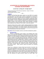
Figure 211. Some typical, but extreme skin disorders – attributed to exposure to cutting uids. [Courtesy of Castrol Industrial].
Cutting Fluids
Many other skin conditions can occur and their
causes can emanate from a number of MWF sources
– going beyond the current scope and objectives of
this chapter. Although through the application of bar
-
rier and conditioning creams, together with clean and
suitable protective clothing, coupled to good washing
facilities, these factors will inevitably lessen the pos
-
sibility of allergic reactions and skin disorders.
Tumours and Cancerous Effects
However, less well known than the allergic and skin
condition previously mentioned, are the other more
serious debilitating health eects on the machine tool
personnel exposed to MWF’s. Industrial experience
suggests that continuous and long exposure to certain
mineral oils can give rise to skin thickening, known as
keratosis, whereby ‘warty-elevations’ (i.e. see Fig. 211b)
can slowly develop over a period of some years. Hence,
these warts will either: remain as they are; disappear;
or in the worse case scenario, become malignant.
A considerable volume of research in both the
chemical and biological elds has been undertaken,
in particular, into the eects of mineral oils in cut
-
ting uids and their aect on worker’s health. Mineral
oils may contain carcinogens – chemical compounds
which are active in causing cancer, with currently, a
number of these compounds having been identied.
ey occur in the main, as polycyclic aromatic hydro-
carbons and, when present in modern rened mineral
oils exist in extremely small proportions – making their
‘positive’ chemical identication exceedingly dicult
to dene. Oil renement by acid treatment has now
been replaced by more modern rening techniques,
including solvent-rened treatment and hydrogenera
-
tion – greatly reducing the undesirable proportions
of aromatic compounds (i.e. these latter compounds
being potential carcinogens)
33
. Moreover, chemical
coolants were originally based on diethanolamine
and sodium nitrate, which for some time have been
suspected of forming ethanolnitrosamine – another
suspected carcinogen. In order to remove this pos
-
sible carcinogen, in 1984, cutting uid manufacturers
removed the nitrates from their formulations. Finally,
33 ‘N-nitrosamines’ , and its chemical compounds are a signi-
cant danger to worker’s health and, the American Environ-
mental Protection Agency (EPA), stated in a report of their
ndings in 1974, that: ‘As a family of carcinogens, the nitrosa-
mines have no equal.’
if one considers permissible exposure levels (PEL’s)
from nitrosamine sources. en, it has been stated that
smoking twenty (untipped) cigarettes per day will de-
liver
0.8 micrograms of various nitrosamines which al-
most
equates to eating a kilogram of fatty bacon per day
(i.e. 6 microgrames), thus, when undertaking these
seriously debilitating smoking/eating toxicity habits
over a signicant period of time, they would consider
-
ably increase the risk of cancer.
Cutting Fluid Mists
Mists resulting from machining operations and their
subsequent collection resulting from the application of
cutting uids, are usually given a low priority by most
manufacturers when compiling a list of potential capi
-
tal items for the workshop. To press this point still fur
-
ther, many companies would much sooner purchase a
new machine tool, than install a special-purpose air
cleaner. In the automotive industries interest in the
level of air quality has some degree of importance,
while elsewhere in smaller production workshops it is
somewhat of a hit-or-miss aair. Given the potential
worker health risks involved today, with high-speed
machining (HSM) coupled to increased tooling cut
-
ting data and higher-pressure coolant supplies (i.e.
see Fig. 195 – top), possibly the greatest threat posed
to a worker is from atomised mists (i.e. sub-
µm size)
within the local atmosphere. Many companies that
incorporate mist collection ltering, will only remove
particles of >4
µm in size, leaving the critical sub-µm
particles still present in the atmosphere.
e earliest chemical interventions to reduce mist
-
ing were high-molecular-weight polymer additives,
that act to stabilise MWF’s and thus suppress mist for
-
mation. With conventional petroleum-based uids,
polyisobutylene has been the preferred anti-mist ad
-
ditive. While, for aqueous-based cutting uids, poly
-
ethylene oxide (PEO) has been utilised. Due to the
susceptibility of PEO’s to shear degradation, repeti
-
tive additions of the PEO polymer are needed to main
-
tain mist reduction. Today, a newer class of shear-
stable polymers has been developed to overcome the
shear degradation as indicated by PEO’s. ese latest
polymer products have been derived from complex:
2-acrylamido-2methlypropane sulphonic acid mono
-
mers, hence, providing longer-term performance in
continuously recirculating aqueous-based MWF sys
-
tems.
So, very high concentration cutting uid mists will
over a short period of time cause: ‘smarting’ of the
eyes; irritation of exposed skin; result in slight irrita
-
Chapter
tion of the mouth and throat; by inhalation, will ir-
ritate the lungs; by ingestion, of the stomach – it may
promote nausea; and aect other internal organs.
If exposed to toxic mists over a long period of time,
this could cause lasting damage to both external and
internal bodily-parts, with at the extreme condition,
promoting the growth of malignant tumours. In order
to restrict misting and minimise operator health risks,
then special-purpose ltering systems have been de
-
veloped, which will be briey reviewed below.
e conventional mist-collection technology,
such as: lters; rotating drums; or cyclones; will col
-
lect particles of >1 µm in diameter, but cannot cope
with smaller sub-µm particles. Further, it has been re
-
ported that brous lters once they are wet, lose ef
-
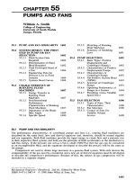
ciency over time – see Fig. 212. erefore, the opti
-
mum manner of removing sub-µm mists are by tting
one of the following:
High-eciency Particulate Air l-
ters (HEPA);
Electrostatic Precipitators (ESP’s); or Fi-
bre-bed systems. Probably the two best systems for re-
moval of sub-µm mist particles are the HEPA and ESP
systems. Each one has its disadvantages, with HEPA l
-
ters being expensive and become clogged, thereby los
-
ing eciency. So, when disposable lter replacements
are needed this hidden replacements cost, will result
in both costly maintenance and disposal. While, ESP’s
need frequent maintenance and cleaning, thus rep
-
resenting a continuous on-going cost burden. Mean
-
while, Fibre-bed systems oer high eciency in mist
collection, but with ease of maintenance, although
they are larger requiring more electrical power to op
-
erate them.
Vegetable Oil-Based MWF’s
Driven by the health and safety concerns of both
workers and manufacturers alike, vegetable oil-based
MWF’s have been developed, to substitute for the same
machining operations as either the mineral-, or petro
-
leum-based uids, currently undertake. It has been
reported that compared with mineral oil-based cut
-
ting uids, the alternative vegetable-based MWF’s, en
-
hance cutting performance by extending tool life while
improving machined surface texture, with the addi
-
tional benet of being an environmentally-friendly
MWF. In particular,
Soybean oils have shown con-
siderable promise as a practical alternative to ‘tradi
-
tional’ MWF’s, where they have improved component
surface texture and reduced tool chatter. One of the
principle reasons for these surface texture and ma
-
chining improvements, is that the vegetable oil-based
MWF’s have enhanced lubricity, coupled with a slight
‘polar-charge’ – which acts to attract the vegetable
oil molecules to the metallic surface being tenacious
enough to resist any subsequent wipe-o. e oppo
-
site is true for a mineral-based oil, where there is no
molecular charge, so oers little improvement in lu
-
bricity.
Mineral-based MWF’s are just straight hydrocar
-
bon, while their vegetable oil counterparts contain
oxygen, which is tenaciously-attracted to the sterile
elevated temperature of the recently-machined work
-
piece’s metallic surface, thus it bonds more strongly
– acting as a result as a better lubricant. Yet another
performance benet of utilising vegetable-based oils
over their mineral-based equivalents, is that they have
a higher ‘ash-point’
34
, which reduces both the ten-
dency for smoke formation and re-risk. Yet another
reason for selecting a vegetable-based MWF over its
mineral-based counterpart, is that it has a high natural
viscosity
35
. Hence, as the machining temperature
increases, the viscosity of the vegetable oil drops more
slowly than for that of a mineral oil. Conversely, as the
temperature
falls, the vegetable oil remains more uid
than its counterpart mineral oil. us, facilitating more
ecient and quicker drainage from both the swarf and
workpiece. e high
viscosity index
36
of vegetable oil
ensures that it provides more lubricity-stability, across
the operating temperature range being found during a
range of machining operations. High viscosity allows
vegetable oils to be used as a slideway lubricant and
for gear lubrication in gearboxes, acting as a so-called:
‘multi-functional uid’ (i.e. see Section 8.9).
Along with the above stated benets, there is also
a down-side to vegetable-based uid applications, the
limitations are that they lack sucient oxidative sta
-
34 ‘Flash-point’ of oils, is the instantaneous ignition of the oil at
a specic temperature, without the aid of a ame. So, in the
case of a Soybean oil it has a ash-point of 232°C, while a typi-
cal mineral oil has a ash-point of just 113°C.
35 ‘Viscosity’ , can be dened* as: ‘e resistance of a uid to shear
force.’ erefore, the shear force per unit area is a constant
times the velocity gradient, with the constant being the coef-
cient of viscosity. SI units are: Newton-seconds per square
metre (Ns m
–2
), denoted by the Greek symbol: ‘µ’. [Source:
Carvill, 1999]
*While another denition for a uid’s viscosity is: ‘e bulk
property of a uid, semi-uid, or semi-solid substance that
causes it to resist ow.’ [Kalpakjian, 1984]
36 ‘Viscosity index’ , can be dened as: ‘A measure of a uid’s
change of viscosity with temperature: the higher the index, the
smaller the relative change in viscosity.’ [Kalpakjian, 1984]
Cutting Fluids
bility for many machining applications. us, a low
oxidative stability means that the oil will oxidise quite
quickly during use, becoming thick as it polymerises
to a plastic-like consistency. Once the oil has become
too thick, or even too thin for that matter, the cutting
tool’s edge(s) will quickly wear-out. Vegetable oils be
-
come oxidised and as a result, will chemically change,
along with their viscosity and lubricating abilities.
ere is some concern among users of vegetable-based
cutting uids, that this oil reacts with the environment
(i.e. oxygen and metals), thus breaking-down, which
is not the case for petroleum-based products. Both of
these uid products oxidise with heat, but vegetable
oils are more susceptible to oxidation. While another
Figure 212. At the lter some droplets and volatiles are re-
moved from the atmosphere, but the remainder pass through
and are re-entrained. Other particulates are ‘indenitely’ re-
tained, but with time reduce lter eciency. Optimum lters
. maximise droplet removal, while minimising evaporation and
re-entrainment – at a reasonable pressure-drop. [Source: Raynor
P. & Leith, D. – Univ. of North Carolina, 2003]
Chapter
drawback to utilising vegetable-based oils, are its lack
of
hydrolytic stability
37
. Typically, when making an
emulsion; obviously oil and water are present; so if ox
-
ygen and some form of alkaline component is at hand,
it may cause certain ester linkages within the vegetable
oil to break down. ese broken-down components
act in a dierent manner to that of the original vegeta
-
ble oil, thereby aecting its cutting uid performance.
Conversely, mineral-based cutting oils are resistant to
hydrolytic reactions. Vegetable oils can support micro
-
bial growth more readily than the equivalent mineral-
based cutting uids. Although this vegetable oil’s bio
-
degradability is ideal for subsequent waste treatment,
conversely, when this product is ‘festering’ in a ma
-
chine’s sump, it becomes both smelly and sour, via its
bactericide and fungicide reactions. Finally, for many
companies, probably the biggest limitation in changing
over to vegetable-based products in machining opera
-
tions is its purchase cost. For example, canola oil, can
cost up to 300% more than its equivalent petroleum-
based product and to compound the nancial problem
still further, costly ingredients are necessary to control
oxidation and enhance its biological stability – consid
-
erably adding to the nished product’s cost.
8.12 Fluid Machining
Strategies: Dry;
Near-Dry; or Wet
So far, this chapter has been principally concerned
with all aspects of ood/wet coolant applications to the
overall machining process. Several other complemen
-
tary cutting strategies can be adopted, these include:
dry; near-dry; together with wet machining; thus, in
the following sections a discussion of these important
issues and concerns will be briey mentioned.
37 ‘Hydrolytic stability’: ester molecules consist jointly of con-
densed fatty acids and alcohols; so the vegetable oils will
naturally exist as esters – oen termed ‘triglycerides’ , these
being a condensation of fatty acid, plus glycerine. Under the
right conditions, the triglyceride can split and revert back to a
fatty acid and glycerine, which acts dierently from that of the
original ester. In the case of mineral-based oils, they do not
contain these ester linkages and as such, will not break down,
nor ‘hydrolise’.
.. Wet- and Dry-Machining –
the Issues and Concerns
In the past twenty-ve years the cost of cutting u-
ids has risen from just 3% of the overall cost of the
machining process, to that of >15% of a production
shop’s cost. Cutting uids and especially ones that are
oil-based products have become something of a liabil
-
ity of late, this is due in the main, to many countries
‘Environmental Protection Agencies’ , strictly regulat
-
ing their ensuing disposal – at the end of their natural
life. In many countries ‘spent’ cutting uids have been
re-classied as either ‘toxic-’ , or ‘hazardous-waste’ ,
moreover, if they have been found to have machined
certain alloyed and exotic material workpieces, they
are under even harsher disposal regulations. Due to
the increasing popularity today of high-speed machin
-
ing (HSM) – more will be said on this subject in the
following chapter – coupled to increased cutting data
and the application of coolants via high-pressure sys
-
tems, these factors have signicantly contributed to
the creation of air-borne mists within the workshop
environment (i.e. see Fig. 212). Such coolant mists
now have even stricter permissible exposure levels
(PEL’s) imposed in the working environment, to regu
-
late and control these air-borne particulates, thereby
minimising workers health risks. us, the cost of:
uid maintenance; record-keeping; with strict compli
-
ance to current and proposed regulations, have rapidly
increased the overall price of cutting uids. In many
manufacturing companies involved in a signicant
amount of machining operations, they are consider
-
ing the strategy of cutting dry, to overcome the cutting
uid-based costs and disposal concerns during and
aer their subsequent usage.
For many companies involved in signicant work
-
piece machining operations, they are unsure if they
could cut all their components ‘dry’. Furthermore, they
are under the impression that to achieve higher cutting
data and ‘hard-part’ machining, then cutting uids
are essential in achieving these objectives. Moreover,
many companies also believe that the cost of chang
-
ing from a ‘wet-’ to ‘dry-machining’ operations would
be prohibitively high. Neither of these impressions are
true. So, by machining ‘dry’ it can be considered as a
standard operational procedure for most metal-cut
-
ting operations, including: turning, drilling and mill
-
ing operations (i.e see Figs. 39, 49 and 168a, respec
-
tively). Moreover, it is not only possible to ‘hard-part’:
turn (Fig. 15) and bore (Fig. 65b); or mill (Fig. 172);
etc.; but these can now be classied as highly-prot
-
able ‘dry-machining’ activities.
Cutting Fluids
Probably the chief obstacle to dry-machining ac-
ceptance, is that conventional wisdom dictates that
MWF’s are vital in attaining acceptable machined n
-
ishes and will considerably extend the tooling’s life. In
many circumstances these are valid points, but with
some of the advanced cemented carbide grades and
high-technology coatings, such tooling can be oper
-
ated at higher cutting data than was previously the
case and, cope with their elevated machining tempera
-
tures. In fact, if
interrupted cutting occurs, the hotter
the
cutting zone becomes, the more unsuitable will be
the
application of a cutting uid – as the thermal shock
38
becomes greater with a ‘wet-machining’ strategy.
Present tool coating technologies are vital to dry-
machining applications, as they both control the tem
-
perature uctuations, while restricting heat transfer
from the cutting vicinity to the insert, or tool. Mul
-
tiple coatings act as a heat barrier because they of
-
fer a lower thermal conductivity to that of the tool’s
substrate and the workpiece material. us, coated
inserts/tooling absorb less heat and as a result, can tol
-
erate higher cutting temperatures, allowing more ag
-
gressive cutting data, whilst not debilitating the tool’s
life. Coating thickness is also important, as the thin
-
ner the overall coatings, the better they can withstand
temperature uctuations, that might otherwise arise,
if thicker coatings were utilised. e main reason for
this improved thermal shock performance of thinner,
rather than thicker tool coatings, is that a thinner coat
is less likely to incur the same stresses, hence, they are
less susceptible to cracking as a result. So, by running
thin coatings in ‘dry-machining’ operations, normally
extends tool edge life by up to 40%, over thicker coat
-
ings
39
.
38 ‘ermal shock/fatigue’ , the cyclical nature of both rapid
heating followed by immediate cooling – in for example face-
milling (i.e see Fig. 213 – top), or when interrupted turning
(e.g. when eccentric turning, or OD/ID machining with either
splines and keyways present), promotes potential tool edge
fracturing – resulting from the cyclic thermal stresses and in-
creased temperature gradients, being exacerbated by the ap-
plication of a cutting uid.
39 ‘in coats-v-thick coats’ , the former coating oers longer life
than the latter coating process. Today, it is normal to utilise the
coating process of: physical vapour deposition (PVD) as this
type of coating is thinner and will adhere/bond more strongly,
than the alternative chemical vapour deposition process. For
example, a TiAlN PVD coated insert/tool can have a hardness
of 3,500 Hv, withstanding cutting temperatures up to 800°C.
‘Dry-machining’ – some Factors for Consideration
•
Adopting a ‘dry machining’ strategy will only make
sense, if
all the cutting processes in the part’s manu-
facture can be performed
without coolant,
•
Only by utilising specialised cutting tool geome-
tries, can ‘dry-machining’ be possible and eective,
•
Tooling typically having special hard multi-layered,
or
diamond-like coatings, etc., to isolate heat and
create
minimal thermal conduction across the tool/
chip interface,
•
Employing cutting tool materials producing sharp
edge geometries – to reduce heat,
•
For drilling operations, utilise ‘so-glide’ coatings –
for
lubrication, with the necessary and appropriate
ecient chip transportation geometries,
•
Speedy and ecient removal of both chips and as-
sociated
steam – by suction – are important factors
in ‘dry-machining’ ,
•
Utilise new machining concepts, plus the latest
fully-enclosed machine tools – whenever possible,
•
Employ faster, rather than slower cutting data, to al-
low the majority of heat to be conned to the evacu-
ated chips.
.. Near-Dry Machining
e strategy of ‘near-dry’ machining is not a new con-
cept, it has been in existence for more than 50 years.
However, this machining and lubricating approach
is still not a universal practice, which is surprising
when one considers the real benets that accrue from
the practice over its ‘wet-machining’ counterpart. As
its name implies, in ‘near-dry’ machining little lubri
-
cant is used – normally vegetable-based oils, meaning
that both cutting uid treatment and its disposal are
eliminated. Further, instigating a ‘near-dry’ machining
strategy means that there are fewer worker health risks
from resultant mists, which might otherwise create: re
-
NB From a metallurgical/materials science viewpoint, the:
TiAlN – PVD tool coating can attribute its superior mechani-
cal/physical properties to an amorphous aluminium-oxide
lm that forms at the tool/chip interface, as some of the alu-
minium of the coating surface oxidises at these elevated ma-
chining temperatures. While, even more exotic multiple-type
diamond-like coatings can be applied and their like, which of-
fer even greater cutting performance – in certain machining
circumstances, when applied to the tool’s cutting edge(s).
Chapter
spiratory problems: skin irritations; etc. e ‘near-dry’
cutting approach can be exploited across a wide range
of either ferrous, or non-ferrous workpiece metals.
Most machine tools are equipped with the capabi-
lity of supplying ood coolant to the cutting process,
together with ‘through-coolant’ tooling systems, mean
-
ing that the cost to recongure for that of a ‘near-dry’
technology is not prohibitive. Assuming the worse-
case scenario of requiring a through-coolant tool
-
ing system, then probably just over $5,000 at today’s
prices should prove sucient capital to complete the
task. Some re-tooling to complement the ‘near-dry’
machining production techniques may be necessary,
allowing the precise application of lubricant to the cut
-
ting edge(s). Further, the user must consider a method
for ecient chip removal from the cutting area. Usu
-
ally, with external ‘near-dry’ cutting operations, the
lubricant is transported within the media of a com
-
pressed air application, via the correct-sized aperture
nozzle – pointed toward the cutting zone. Control of
the volume of lubricant delivery to the tool and work
-
piece area is critical, with the common misconception
being that
more lubricant is better! e optimum ar-
rangement for ‘near-dry’ lubricant application, is when
the
minimum of over-spray and resultant misting does
not occur.
With external ‘near-dry’ operations, dispensing
systems usually consists of reservoir metering pumps
and valves, being mounted on the machine tool’s exte
-
rior – at some convenient location. While the nozzles
are strategically-mounted so that they can easily be
directly aimed at the tool’s cutting edge(s). Normally,
the nozzles are a manufactured from either copper,
or plastic and ‘snap-together’ – being much smaller
in size than their ‘wet-machining’ counterparts. For
internal machining operations, having tooling with
‘through-the-nose’ delivery, the lubricant is mixed
with compressed air prior to delivery to the cutting
zone. e admixing of compressed air and lubricant
keeps the lubricant in suspension, with these oil par
-
ticles being broken-down into minute particles prior
to being fed into the compressed air jet stream – on
their way to the tooling.
For ‘conventional’ ood coolant delivery the sys
-
tems, the coolant channels are lled with cutting uid,
which inevitably nds its way to the cutting zone. If
however, in a ‘near-dry’ machining conguration, a
heavy mist of lubricating oil oats through the com
-
pressed air, attempting to negotiate all of the twists
and turns on its way to the cutting zone, this may pres
-
ent a potential lubrication clogging/starvation prob
-
lem. Hence, for a successful ‘near-dry’ delivery system,
the lubricant channels need to be smooth and even,
with direct ows from the coolant pump to the cutting
zone.
A basic misapprehension by some machine tool
designers and manufacturers, is that copious volumes
of ood coolant are necessary to remove large quanti
-
ties of swarf. In fact, just the opposite can occur, as
wet chips will not only pack tightly together but have
a surface tension property to them, tending to make
them adhere to machine tool surfaces (i.e. see Foot
-
note 29,
‘Lang’s chip-packing ratio’ in Chapter 2). is
is not generally the case for ‘near-dry’ lubrication, as
the chips here, have a thin layer of non-oxidising lu
-
bricant surrounding them and with their evacuation
velocity – aer being machined, coupled to gravita
-
tional eects, means that they will fall to the bottom
of the swarf tray, or into the chip conveyor. It is good
working practice to use the external air-only supply’s
blow-o nozzles to clear away chips form the cutting
area
40
, however, it is not recommended to use the oil/
mist to achieve chip clearance, as it will simply blow
the lubricant straight past the cutting edge(s), while
probably creating an unwanted oil-misting problem.
It is possible to incorporate both ‘wet-’ and ‘near-dry’
lubrication systems onto the same machine tool. It
has been reported that for external/internal work the
change-over from one system say, from ‘wet-’ , to the
other – ‘near-dry’ , takes about 3 minutes to complete.
For ‘near-dry’ machining to be successful, it de
-
pends upon various factors, including: workpiece ma
-
terial to be machined; tool geometry and its coating(s);
speeds and feeds selected; plus other important fac
-
tors. If applied correctly, ‘near-dry’ machining has sig
-
nicant direct and indirect benets to the machining
process as a whole.
Economics of: ‘Dry-’; ‘Near-Dry’;
and ‘ Wet-Machining’.
For any tool and workpiece lubrication strategy to
operate eectively, a range of cost factors need to be
considered, regardless of the method of machining
40 ‘Chilled compressed air’ , has been successfully utilised in the
past for not only removing chips from the cutting vicinity,
but on certain materials, the continuous application of chilled
compressed air acts simply as a form of ‘basic lubricant’ for
the cutting process in hand.
Cutting Fluids
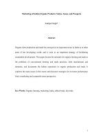
undertaken. In Fig. 213, a table has been constructed
to show the relative merits of the three machining
strategies previously discussed, namely: ‘dry-’; ‘near-
dry’; or ‘wet-machining’. e cost component for each
of these lubrication strategies has been broken down
into its relevant parts, with some of them not being ap
-
plicable to every lubrication application. If one ignores
the individual cumulative factor in the overall cost
and simply looks at the ‘bottom-line’ , namely, the total
relative costs for each process, then a clear message is
being given here! Explicitly, that ‘wet-machining’- in
certain cases, when compared to ‘dry-machining’ is
Figure 213. Indicates the comparative costs for utilising either: ‘dry-’, ‘near-dry-’ or ‘wet-machining’ strategies.
Chapter
>330% more expensive overall, this being a good rea-
son to look carefully at employing ‘dry-machining’
techniques – when applicable!
In Appendix 14, a MWF ‘trouble-shooting guide’
has been included, to help establish the relative causes
and remedies for certain uid-related problems – as
they arise.
References
Journals and Conference Papers
Antoun, G.S. e Pressure’s On to Improve Drilling [High-
Pressure and Volume Coolant Supply]. Cutting Tool
Eng’g., 59–68, Feb., 1999.
Batzer, S. and Sutherland, J.
e Dry Cure for Coolant Ills.
Cutting Tool Eng’g., 34–44, June, 1998.
Benes, J.
Life Support – for Cutting Fluids, American Ma-
chinist, 42–46, Feb., 2007.
Benes, J.
Engineering Metalworking Fluids. American Ma-
chinist, 48–51, March, 2007.
Boyles, C.M.
Managed Fluid Care. Cutting Tool Eng’g.,
40–45, Jan., 2002.
Brutto, P.
Water Hazard [Leaching Cobalt Binder from WC
Tooling]. Cutting Tool Eng’g., 50–56, Dec., 1996.
Da Silva, M.B., Machado, A.R. Wallbank, J.
On the Mecha-
nism of Lubrication in Single Point Cutting. Int. Conf.
on: Behaviour of Materials in Machining, Straord-
upon-Avon (England), Pub. by: IOM Communications
Ltd, 79–89, Nov. 1998.
Davidian, S.
Setting Standards [Metalworking Fluid Stand-
ards]. Cutting Tool Eng’g., 52–55, Sept., 2001.
DeChire, L.
Testing the Overall Performance of Cutting
Fluids. Lubric. Eng’g., Vol. 34 (5), 244–251, 1978.
DeChire, L.
Mechanical Testing and Selection of Cutting
Fluids. Lubric. Eng’g., Vol. 36 (1), 33–39, 1980.
Deodhar, J.
Soluble Cutting Fluids: Chemistry, Management
and Control. Int. Conf. on Industrial Tooling South-
ampton, UK, Shirley Press Ltd., 151–158, Sept. 1995.
Dunlap, C.
Should you try Dry? [Dry Machining]. Cutting
Tool Eng’g., 22–33, Feb., 1997.
Eade, R.
Are Metalworking Fluids a reat to Health? Cut-
ting Tool Eng’g., 80–86, Aug., 1998.
El Baradie, M.A.
Cutting Fluids: Characterisation Part I.
Int. Conf. On Adv. In Matls and Process. Technol., Vol.
III, Dublin City Univ. Press, 1999–2010, Aug., 1993.
El Baradie, M.A.
Cutting Fluids: Recycling and Clean Ma-
chining Part II. Int. Conf. On Adv. In Matls and Process.
Technol., Vol. III, Dublin City Univ. Press, 2011–2019,
Aug., 1993.
Excell, M.
Well Oiled Machines [Machine Tool Lubrica-
tion]. Metalworking Production, 53–56, Dec., 1995.
Folz, G.
Treat MWFs [Metal Working Fluids] Right. Cut-
ting Tool Eng’g., 36–42, Oct., 2003.
Graham, D.
Dry Out [Dry Machining]. Cutting Tool Eng’g.,
56–65, Mar., 2000.
Gugger, M.
Putting Fluids to the Test [Testing Methods].
Cutting Tool Eng’g., 54–62, Aug., 1999.
Howard, R.
Types of Cutting Fluids used on Turning/Ma-
chining Centres. Int. Conf. on Industrial Tooling (South-
ampton, UK), Shirley Press, 140–150, Sept. 1995.
King, N.
Ah, the Smell of It [Microbiological Colnat Ef-
fects]. Manufact. Engr., 7–9, Dec., 1991/Jan. 1992.
Krahenbuhl, U.
Lightening [Coolant Lubricity]. Cutting
Tool Eng’g., 28–34, Sept., 2002.
Leep, H.R.
Investigation of Synthetic Cutting Fluids in Drill-
ing, Turning and Milling Processes. Lubric. Eng’g., Vol.
37 (12), 715–721, 1981.
Manfreda, J. and Elenteny, D.
Cool Savings, Cutting Tool
Eng’g., 42–51, Feb., 2006.
Phillips, D.
Under Pressure [High-Pressure Coolant Deliv-
ery]. Cutting Tool Eng’g., 48–53, Jan., 2000.
Phillips, D.
Dry Run [Dry Drilling]. Cutting Tool Eng’g.,
34–40, Feb., 2000.
MCCabe, J.
Dry Holes – Dry Drilling Study. Cutting Tool
Eng’g., 40–50, Feb., 2002.
Protch, O.
Fluid Cutting. Cutting Tool Eng’g., 40–43, Dec.,
2001.
Rahman, M., Senthil Kumar, A. and Salam, M.U.
Experi-
mental Evaluation on the Eect of Minimal Quantities of
Lubricant in Milling. Int. J. of Mach. Tools and Manu-
fact., Vol. 42, 539–547, 2002.
Shanley, A.
Mist Collection: e Pressure is On. Cutting
Tool Eng’g., 46–51, June, 2003.
Sluhan, W.
Don’t Recycle – Keep your Coolant. Cutting Tool
Eng’g., 53–55, Oct., 1993.
Sluhan, W.
Selecting Coolants: Why and How. Cutting Tool
Eng’g., 56–65, Oct., 1995.
Sluhan, W.
Does Your Machine Like Its Coolant? [Water-
miscible Cutting Fluid Concerns]. Cutting Tool Eng’g.,
62–69, April, 1996.
Sluhan, W.
Humans and Cutting Fluids [Health Issues].
Cutting Tool Eng’g., 88–92, June, 1996.
Sluhan, W.
Pure Water – Isn’t Hard to Find [Hard Water
Problems]. Cutting Tool Eng’g., 28–32, Dec., 1996.
Sluhan, W.
Bubble Trouble [Foaming Eects]. Cutting Tool
Eng’g., 24–28, April, 1997.
Sluhan, W.
Itching for a Solution [Causes of Dermatitis].
Cutting Tool Eng’g., 36–43, Dec., 1997.
Sluhan, W.
e Good, the Bad and the Smelly [Bacterial Ef-
fects]. Cutting Tool Eng’g., 24–32, Mar., 1998.
Smith, A. Lagerberg, S. Dahlam, P. and Kaminski, J.
High-
pressure [Coolant] Jet-assisted Turning, Int. Conf. on
Industrial Tooling Southampton, UK, Molyneux Press
Ltd., 62–71, Sept. 1999.
Cutting Fluids
Smith, G.T. Managing and Controlling Cutting Fluids in a
Flexible Manufacturing Environment. Proc. of Manag-
ing Integrated Manufacturing, Keele Univ. Press, Vol.1,
491–503, 1993.
Smith, G.T.
Wet and Dry Machining – Understanding the
Key Issues. Metalworking Production, 22–24, Oct.,
2000.
Smith, P.L.
Coolants and Cancer: Fact or Fiction? American
Machinist, 46–50, Dec., 1996.
readgill, J.
Animal, Vegetable, or Mineral [Sump-cleaning
Strategies]. Cutting Tool Eng’g., 30–35, Sept., 1993.
Walz, T.
Fine Ideas [Ultra-ltration]. Cutting Tool Eng’g.,
48–52, May, 2002.
Woods, S.
Going Green [Vegetable Oils], Cutting Tool
Eng’g., 48–51, Feb., 2005.
Yang, C.C.
e Eects of Water Hardness on the Lubricity of
a Semi-synthetic Cutting Fluid. DeChire, L. Testing the
Overall Performance of Cutting Fluids. Lubric. Eng’g.,
Vol. 35 (3), 133–136, 1979.
Woods, S.
Going Green [Alternative: Vegetable-based
MWF’s]. Cutting Tool Eng’g., 48–51, Feb., 2005.
Woods, S.
Nearly Dry [Nearly-dry Machining]. Cutting
Tool Eng’g., 58–64, Mar., 2006.
Books, Booklets and Guides
Byers, J.P. Metalworking Fluids. Marcel Dekkar (NY), 1994.
Carvill, J.
Mechanical Engineer’s Data Handbook. Butter-
worth-Heinemann Pub., 1997.
Hartley, D.
Cutting Fluids – eir Care and Control. Reprint
from: Maintenance Eng’g., May, 1979.
Mang, T.
Wassemischbare Kühlschmierstoe für die Zer-
spanung [Water-miscible Metalworking Fluids]. Vol.
61, Kontakt and Studium, Tribotechnik. Expert Verlag,
Grafenau, 1980.
Kronenberg, M.
Machining Science and Application. Per-
gamon Press (NY/London), 1966.
Metalworking Fluids. Pub. by: Verlag/Cincinnati Milacron,
1991.
Metal Working Fluids Guide. Kuwait Petroleum Inter-
national Lubricants Pub.
Moubray, J.
Reliability-centred Maintenance, Butterworth-
Heinemann , 1996.
Nachtman, E.S. and Kalpakjian, S.
Lubricants and Lubrica-
tion in Metalworking Operations. Marcel Dekkar (NY),
1985.
Robertson, W.S.
Lubrication in Practice. Esso Petrol. Co.
Ltd.,/Macmillan Educ. Ltd., 1987.
Schey, J.A.
Tribology in Metalworking – Friction, Wear and
Lubrication. ASM Pub. (Ohio, USA), 1983.
Sluhan, C.
Cutting and Grinding Fluids: Selection and Ap-
plication. Soc. Of Manufact. Engrs., (Dearborn, Mich.,
USA), 1992.
Smith, G.T.
CNC Machining Technology: Vol. 2: Cutting,
Fluids and Workholding Technologies. Springer-Verlag,
1993.
Smith, G.T.
Condition Monitoring of Machine Tools (Chap-
ter 9). In: Handbook of Condition Monitoring, 1
st
Ed.
(Edited by: Rao, B.K.N.), Elsevier Advanced Technol
-
ogy, 1996.
Talking About – Cutting Fluids. Castrol (U.K.) Ltd, Pub.
No.: IND 71b/9/91, Sept., 1991.
Talking About – Health and Safety (3
rd
Ed.). Castrol (UK)
Ltd., 1990.
Yust, M.S. and Becket, G.J.P.
Microbiology eory and Prac-
tice in Metalworking Fluids. Reprint from: Ind. Lubric.
& Trib., Nov./Dec. 1980.
Chapter