Báo cáo hóa học: "Research Article Microarchitecture of a MultiCore SoC for Data Analysis of a Lab-on-Chip Microarra" docx
Bạn đang xem bản rút gọn của tài liệu. Xem và tải ngay bản đầy đủ của tài liệu tại đây (1.85 MB, 11 trang )
Hindawi Publishing Corporation
EURASIP Journal on Advances in Signal Processing
Volume 2008, Article ID 520641, 11 pages
doi:10.1155/2008/520641
Research Article
Microarchitecture of a MultiCore SoC for Data Analysis
of a Lab-on-Chip Microarray
G. Kornaros
1, 2
and S. Blionas
2
1
Electronic and Computer Engineering Department (ECE), Technical University of Crete, 73100 Chania, Greece
2
Department of Applied Information Technology and Multimedia, Technological Educational Institute of Crete, 71004 Heraklio, Greece
Correspondence should be addressed to G. Kornaros,
Received 30 November 2007; Revised 21 May 2008; Accepted 24 June 2008
Recommended by P C. Chung
This paper presents a reconfigurable architecture of a lab-on-chip (LoC) microarray device capable to process data either in
genotyping or in gene expression applications in a fraction of the time that is required by the usual software methods running on
a standard computer. The entire LoC consists of a microfluidics part for the sample preparation and hybridization, a microsystem
part including the application specific array of sensors for the electronic detection, and finally a reconfigurable processing part for
the data analysis. The proposed data processing and analysis electronic module are an embedded multicore reconfigurable system-
on-chip designed to analyze data from the forthcoming high-density oligonucleotide microarrays. The proposed architecture
employs reconfigurable technology and has the capacity to process data from microarrays of various sizes from small size ones
used in genotyping up to large-scale gene expression arrays. Additionally, the embedded processing cores feature reconfigurable
circuitry for implementing the intense part of the processing, supplementing the various computational needs of the diverse
applications for microarray real-time data processing and for a scalable reconfigurable architecture to handle also the future high-
density microarrays.
Copyright © 2008 G. Kornaros and S. Blionas. This is an open access article distributed under the Creative Commons Attribution
License, which permits unrestricted use, distribution, and reproduction in any medium, provided the original work is properly
cited.
1. INTRODUCTION
Microarrays are a significant part of the lab-on-chip (LoC)
research area and are dedicated either for the parallel
assessment of gene expressionfor hundreds or thousands of
genes in a single experiment,or for genotyping molecular
diagnostics applications and particularly for pharmacoge-
nomics. Despite the wideemployment of microarrays in
molecular biology and genetics, technical problems still exist,
for example, identifying and recognizing reliable data using
image processing techniques. Currently, the microarray data
analysis is done with offline photographic methods, and
further quality assessment of the data, after segmentation
spot/background, grid matching, and noise suppression [1,
2], follows. These further data processing steps require a
larger number of data to be stored, particularly when the
number of spots on the microarray is of several thousands
(gene expression applications), and then to process them for
the quality assessment. Those issues so far did not allow the
full integration and operation of the LoC microarrays either
as standalone devices for possible consumer applications
(e.g., self-tests), or as intelligent systems creating much less
data for further processing [3]. Electronic hybridization
detection allows high integration level of LoCs but the
reading of the array of the sensors and the further data
processing in case of large microarrays (the number of
the sensors on the microarray with embedded electronic
detection capability may reach nowadays several thousands),
and also the on-chip processing of microarrays, still remain
an open research issue [4–7].
This paper presents the architecture of the electronic
part of a fully integrated robust biomedical, biodiagnos-
tics electronic microsystem. This architecture processes
the measurements of the electronic hybridization detec-
tion sensors and hosted at a disposable device-cartridge
which first extracts the DNA from a blood drop, then, it
amplifies the fragmented tiny DNA samples (using PCR)
and finally runs biological protocols which evaluate the
analyzed substance. It can be encapsulated in a single,
portable, self-contained device-unit, significantly reducing
the risks of cross-contamination inherent in conventional
analysis methods. An array of embedded sensors monitors
2 EURASIP Journal on Advances in Signal Processing
the hybridization of the sample with the biological material
put on the microarray spots. The LoC is controlled by the
proposed architecture that monitors and adjusts the process
of the data produced by the electronic hybridization detec-
tion. Subsequently, it executes an automated methodology to
flexibly execute normalization, transformation, and removal
of unreliable spot raw data. The proposed architecture due
to its modularity is capable to further process data ranging
from small microarrays (few hundreds of spots) up to
large multithousands of spots microarrays producing vast
amount of data and evaluate the final results for molecular
diagnostics examinations.
Targeted application areas are mutation detection for
gene expression, genotyping, and pharmacogenomics. Addi-
tionally, the proposed architecture of the LoC device could be
used also for prediction, prevention, and even early diagnosis
or predisposition of specific diseases. Molecular diagnosis of
infectious diseases, virus molecular detection, and so forth
are also possible applications. Forthcoming genetic tests not
only will be dedicated for diagnostic of diseases but also
for personalized medicine treatment (pharmacogenetics).
They will also provide information to optimize drug therapy
increasing the efficiency and minimizing the adverse effects
of the developed drugs.
Section 2 of the paper describes the state of the art of
the microfluidics sample preparation module of the LoC,
and of the electronic hybridization detection presenting
two different approaches, the photonic sensors alternative
and the capacitive sensors one. Section 3 presents the data
processing algorithms that are required to analyze the
electronic hybridization detection sensor data and decide
about the existence of the examined mutations. Section 4 is
describing two alternative architectures for the data analysis
of LoC data. Finally, Section 5 is presenting an emulation
ofthesearchitecturesaswellasperformanceevaluation
results, and Section 6 shows the processing of the data of a
microarray with 8500 spots.
2. STATE OF THE ART FOR THE LAB-ON-CHIP
The lab-on-chip consists of subsystems for the sample
preparation for the electronic hybridization detection and
the data analysis. The sample preparation subsystems in
case of DNA analysis concerns DNA extraction, PCR, and
hybridization (microfluidics subsystem). Then, electronic
hybridization detection subsystem concerns the measure-
ment of hybridization “degree” using dedicated biosensors
and their associated reading circuitry. Finally, data analysis is
the targeted subsystem by this paper and concerns the flow of
data from the reading circuitry to the data analysis subsystem
and the processing of data by this. Below, there are presented
indicatively state of the art implementation approaches for
the first two subsystems that are not the target areas of
this paper, namely, the sample preparation and electronic
hybridization detection subsystems.
DNA extraction and amplification are usually prerequi-
site steps that are needed so as to provide a sufficient number
of copies of the target gene sequences to enable visualization
using specific detection modules, and thus identification
or characterization of gene sequences. Conventional genetic
analysis in clinical laboratories typically requires bench-
top equipment and either manual or robotic transfer of
liquids (e.g., 10–500 uL) between tubes (or microwells in the
case of microliter plates) for separate steps of the process.
Using conventional approaches, DNA extraction is most
commonly implemented by initially rupturing the cells (cell
lysis) in a buffer solution (e.g., a solution including SDS),
then capture of the released DNA with either silica particles
in a filter-type format, or silica-coated paramagnetic beads
which can then be immobilized with a magnet. This allows
all other cellular debris to be washed away, after which
this “template” DNA can be eluted from the beads and
resuspended in a liquid buffer ready for amplification
using the polymerase chain reaction (PCR). PCR involves
cycling the DNA through a series of temperatures using a
programmable thermal cycler. Initially, the two strands of
the template DNA duplex are separated by denaturation
at
∼95
◦
C, then short synthetic DNA “primer” sequences
are annealed to the ends of the target section of template
sequence (i.e., at a temperature usually between 50–60
◦
C),
from which the Taq polymerase enzyme “zips” together the
nucleotides present in the reaction mixture to build a new
DNA sequence complimentary to template. By cycling the
reaction through this process, usually between 25 and 40
times, the number of available copies of DNA increases
exponentially, so as to yield a sufficient of DNA enabling
detection and analysis. DNA analysis will continue either to
identify specific sequences in specific parts of the DNA or
to compare the expression of genes of various samples and
extract results for the role of genes in specific diseases.
Microfluidics parts of LoCs usually implement these
sample preparation steps fully automatically. The early
years usually were made by silicon and glass. Microfluidics
technology has made great strides in recent years [8–10].
Nowadays a trend toward polymers as substrate material
hasbeen observed ([11], for review see Zhang et al. [12]).
Plastic substrates are less expensive and easier to manipulate
in mass production than silica-based substrates. Advances in
polymer engineering have led recently to the development
of a biochip device consisting of a plastic microfluidic chip,
a printed circuit board (PCB), and a Motorola eSensor
microarray chip. The plastic chip includes a mixing unit for
rare cell capture using immunomagnetic separation, a cell
preconcentration/purification/lysis/PCR unit, and a DNA
microarray chamber.
The developed LoC uses composite materials based
mainly on plastic foils (especially PDMS) and different
types of fibers (especially silicon carbide fibers). A modular
technology for the micrfluidics part of the biochip is under
development in the Tyndall National Institute. A similar
technology, without the use of metallized fibers, is also
reported in the literature [11].
Concerning the hybridization chamber that hosts the
electronic detection part of the LoC, it was designed
considering various constraints and functions. The main
chamber that accommodates the hybridization of the sample
DNA with the biological material of the spots is as small as
possible; it allows the measurement of all biological spots
G. Kornaros and S. Blionas 3
with pitch 300 μm centre to centre and 170 μm diameter
spots. A heater controls and stabilizes the temperature.
The chamber is isolated from external light and has the
smallest auto fluorescence as possible. The packaging of the
chamber onto the sensors is predicted to be easy for the
final assembly of the device. Probes grafting is performed
before the chamber assembly. If optical detection is employed
then alignment between biological spots and sensors is
mandatory, while in the case of the capacitive sensors this
is not required. The whole system is compact and is designed
for optimized volumes (capillaries, hybridization chamber,
tanks). Finally, it is of low consumption, robust, while at the
same time ensures waterproofness.
Several protocols for microarray-based SNP and muta-
tion analysis have been developed (as reviewed in [13]).
There is the tiled arrays approach [14] that allows a variety
of electronic detection techniques. Tiled arrays involve the
generation of an array of oligos that vary in specific positions
in order to create perfect matches to the fragmented DNA
molecules which will bind strongly or mismatches that will
result in weaker binding.
In the photodetection context, tiled oligonucleotide
arrays are suitable for single color detection [14]. The
fragmented DNA molecules are labeled with a fluorophore
probe, and the more or less binding pairs result in relative
intensities of the oligo spots that have to be compared. This
requires the same amount of functional oligo to be deposited
(by spotting) or synthesized [15]ateachspot.Theaim
is to minimize variations in the amount of arrayed oligo,
which will impede the analysis of single color intensities. The
optical setup for the detection includes an excitation light
source, typically LEDs or a laser, optical filters to separate the
excitation light wavelength for the fluorescence wavelength,
and a detector. There is a range of microarray scanners
available for scanning and detection of DNA microarray-
based platforms. The lowest cost and least sensitive is a
CCD- (or CMOS-) based imaging system, where the whole
microarray is illuminated with the excitation light source,
and image processing is used to determine the results.
Alternatively, a laser scanning-based microarray scanner can
be used. In this configuration, a laser beam is raster scanned
across the microarray device. The fluorescence is collected
via appropriate optics and filters into a photomultiplier tube
(PMT). Also a 2D array of photon counting sensors on a
single chip could enable detection of images of fluorescent
hybridized DNA samples. It utilizes the high speed operation
and low light level detection capability of the 2nd generation
silicon detectors, the Geiger Mode-APD [16]. These devices
produced using CMOS compatible processing are low power
as appropriate for POC and portable applications and will
have a low-cost base.
MEMS sensors are based on mechanical movements
and deformations of their micromachined components,
such as single-clamped suspended beams (cantilevers),
double-clamped suspended beams (bridges), or suspended
diaphragms.
In capacitive detection, the displacement is measured as
a change in the capacitance of a plane capacitor.An approach
for the detector array based on the stress induced on a thin
Contacts
Si membrane
SiO
2
Cavity
Substrate
Protein acceptor
(a)
Protein
(b)
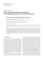
Figure 1: Hybridization process using capacitive sensors.
silicon membrane due to reactions between the receptor
DNA deposited on the membrane surface and the sample
under investigation will be explored. This kind of detectors
has been successfully applied in biological applications
employing silicon cantilevers and optical or piezoresistive
detection. Capacitive detection could challenge the sensitiv-
ity and flexibility achieved by both of these techniques.
Capacitive DNA sensors arrays based on the exploitation
of surface stress changes and subsequent bending of an ultra
silicon thin membrane are to be fabricated. The membrane
will seal the capacitor plates from the electrolyte solution
thus enabling capacitive detection.
In this array, each element of the array will be a capacitor
comprised of an ultra thin silicon membrane suspended over
a cavity and a counter electrode on the substrate. Operation
of the device will rely on the induced stress due to the
reaction between the receptor DNA, a number of ultra thin
silicon membranes covering a shallow cavity formed into a
silicon dioxide layer etched on a silicon substrate containing
the counter electrode of the capacitor detector. In Figure 1,
the basic idea is illustrated. The hybridization process (b)
results in membrane deflection due to the change of the
surface free energy that eliminates the need for attaching
labels to detect specific binding. Special provision will be
taken so that the device accommodates for the microfluidics
to be incorporated on the system.
3. MICROARRAY DATA PROCESSING ALGORITHM
Statistical analysis of microarray data can essentially process
massive amounts of data and can also adjust for various
sources of variability in order to identify the important genes
or existing mutations amongst a large number which are
interrogated. This section summarizes some of the issues
involved and provides a brief review of the processing
algorithm mostly used by the researchers and will be
accommodated by the proposed architecture.
All microarray LoC experiments involve a number of
distinct steps. The design of an experiment involves the
following:
(i) the number and the type of the genes’ mutations to
be interrogated,
4 EURASIP Journal on Advances in Signal Processing
(ii) for each of the above mutations of a gene, the exact
sequence of bases named oligos should be printed on
the LoC,
(iii) the design of appropriate sources of RNA to be
hybridized, and
(iv) the number of replicates for each of the oligos on the
LoC for increased statistical confidence.
After hybridization that completes the data acquisition from
the LoC sensors takes place, next several data filtering
steps must follow. The data must be processed to acquire
mutant and wild values; these are represented as red and
green in traditional microarrays. In addition, the background
intensities should be estimated so as to correct the mutant
and wild values. The aim is to adjust for sensor-bias and
for any systematic variation other than that due to the
differences between the RNA samples being examined. Then,
the corrected values are further analyzed to decide about the
existence of a mutation in a sample or to select differentially
expressed (DE) genes or to find groups of genes whose
expression profiles can reliably classify the different RNA
sources into meaningful groups. The discussion in this
section corresponds roughly to these data analysis steps.
The following notation will be used throughout this
section. The mutant and wild sensor measurements are
denoted as M
f
and W
f
for each spot. The background
intensity will be I
b
. Having estimated the background
intensity, it is almost universal practice to correct the mean
values of the measured M
f
and W
f
intensities by subtracting
the mean value of the background, M
= M
f
− I
b
and W =
W
f
−I
b
. These adjusted intensities form the primary data for
all subsequent analyses.
The motivation for background adjustment is that
a spot’s measured intensity includes a contribution not
specifically due to the hybridization of the target to the probe.
For example, nonspecific hybridization may occur and/or
fluorescence may be emitted from other chemicals on the
detection part of the LoC (in the case of photosensor-based
hybridization detection). If such a contribution is present, we
wouldliketomeasureandremoveitsoastoobtainamore
accurate quantification of the actual hybridization. Research
has begun as discussed in [17] on more sophisticated
methods of background adjustment which will produce
positive adjusted intensities even when the background
estimate happens to be larger than the foreground. Empirical
experience suggests that local background estimates often
overestimate the true background while the morphological
method may underestimate it, and these differences have
amarkedimpactontheM-values for less intense spots.
There is a need for further research on adaptive background
correction methodologies which can produce intensities
with consistent behavior regardless of background estimator
method used.
The data produced by the developed LoC after hybridiza-
tion are processed to infer if specific mutations are present in
the examined sample and consequently to decide on what is
the appropriate medicine cluster that a patient should get.
Assuming that N replicas have been chosen, the microarray
is partitioned to N subarrays that correspond to N groups of
sensors. Each subarray is spotted with the wild-type probes
and with the mutant probes. There are also spots of an
oligo that will never hybridize in order to be used as control
and background reference; these are the nonbinding control
probes. The calculations to be carried out on the data for
a mutation for both the wild and the mutant spots are
summarized by the steps of the following algorithm.
Step 1. calculation of the mean values for the wild, the
mutant and the nonbinding control spots:
X =
1
N
N
i=1
x
i
,(1)
where N is the number of replicas for each probe.
Step 2. calculation of standard deviation (SD) for the wild,
the mutant and the nonbinding control spots:
σ
=
1
N
N
i=1
x
i
−X
2
. (2)
Step 3. the coefficient of variation is then calculated and
expressed as a percentage:
CV%
=
Standard Deviation
Mean
∗
100 (3)
If the calculated CV% is below 60 (as studied in [11]) then
jump to Step 5.
If the calculated CV% is over 60 then continue to Step 4.
Step 4 (Calculation of new mean values excluding the
outliers). Assuming that we would like to keep our mea-
surements within the 95% confidence interval, then this
defines a distance of D
= 1.96∗SD, where we will keep
our measurements. All measurements outside this region
(MeanValue
±D) will be considered as outliers and they will
be excluded. Calculation of new mean values is excluding
the outliers. This final mean value of the reference group is
memorized to be used in the next step for all the other groups
of the LoC.
Step 5 (Background correction). Sources of variation in
the microarray such as unequal quantities of starting RNA
or differences in hybridization conditions across the array
usually affect expression intensities. It is therefore required
the task of correction of microarray data so that to determine
more meaningful and accurate biological data. This is
referred to as background correction. The final values for
wild and mutant probes are calculated by subtracting the
background mean value I
b
from the calculated mean value
after the outliers step (for both wild and mutant), so as to
result with the final hybridization detection value of a probe.
Step 6 (Decision about the existence of an SNP). The
calculations produce the ratio of the mutant and the wild
mean values (M/W). According to the research results in
[11], if this ratio is greater than 2 then the specific mutation
is considered as existing.
G. Kornaros and S. Blionas 5
An alternative approach is to use the log-differential
expression ratio. This is expressed as log
2
(M/W) = log
2
M −
log
2
W for each spot. It is convenient to use base-2 logarithms
for the ratio M/W so that M is units of 2-fold change. On this
scale, M
= 0 represents equal expression, M = 1 represents
a 2-fold change between the RNA samples, M
= 2 represents
a 4-fold change, and so on. Hence, in case of using log values
then the threshold is the value 1.
Other statistical approaches commonly used to improve
significance estimates are a penalized t-test and a Z-
test using intensity-dependent variance estimates; these are
assuming that photographic methods are used to extract
the hybridization results, but also apply to our capacitive-
based microarray. However, as shown in [17], the major
shortcoming of the t-statistic is that the replicate ratios
can occasionally be extremely similar due to randomness,
producing thus an artificially low standard deviationand
high t values. False positives stemming from this effect
prevent the standard t-statistic from serving as a reliable or
useful test of which genes are truly regulated.
The above steps are repeated for all the interrogated
mutations in the LoC, and according to the predefined
rules the cluster where a patient belongs is defined and an
indication on the disposable LoC informs the consumer
(patient), about this decision.
4. SYSTEM-ON-CHIP ARCHITECTURE FOR
MICROARRAY DATA ANALYSIS
We describe and evaluate in detail the two alternative
architectures of the single-core and multicore approach.
Also, the details for the data analysis of the microarray of a
custom Lab-on-Chip are described.
4.1. Microarray data analysis on a single core CPU
with accelerator
The reading process of the sensors’ values is the first
step before the data analysis part; this reading requires a
conversion of the indication of the analog sensor to a digital
value. Depending on the sensor type, two options exist for
the analog to digital conversion. In case of the photosensors
traditional A/D, converters are used and their parallel output
is forwarded to the data bus to be transferred to the
appropriate processing core for further data analysis. In case
of the capacitive sensors, capacitance measurement is carried
out by measuring frequency; an interface reader (IFRD)
is a simple circuitry converting the capacitance changes to
digital pulses and subsequently to an arithmetic value if
the microarray is capacitive-based. The conversion requires
about 1 microsecond for each measurement as discussed in
[18], and it allows for a frequency of reading up to 1 MHz.
Using one reading circuitry, it will need a total of 1 second
for 10
6
spots. These data are forwarded to the processing core
in the case of single core architecture.
As a first approach, the entire microarray could be read
and monitored by a single core microprocessor, yet simple
and energy efficient in order to comply with the require-
ments of a cheap, portable, and flexible microsystem for
Sensor
micro-
array
Memory
controller
I/F
RD
MicroBlaze
SRAM
Flash
Figure 2: Single core data analysis architecture.
pharmacogenomic applications. This microprogrammed-
based system offers itself for easy update of the algorithms in
firmware; these algorithms perform the data processing while
at the same time do not cause excessive processing delay.
However, high-throughput microarrays with thousands of
spots, for achieving real-time performance (less than 1
second waiting for getting the result) will obviously require
more processing power as it will be shown at the next section.
In the genomics area, the biologists need to compare the
expression level of thousands of genes in the same time
using at the same time many of these high-end microarrays
in parallel. In the next part of the section, we present a
reconfigurable system-on-chip with the capacity to handle
such applications in real time.
The organization of the LoC microsystem board is
depicted in Figure 2. The device is controlled by the firmware
loaded in single core microprocessor (MicroBlaze operating
at 100 MHz). This same core will be responsible to provide a
user interface and postprocessing the analysis results via the
μBlaze CPU core. The embedded microprocessor executes
the feature extraction algorithm to decide in which category
the patient under analysis belongs to.
In order to evaluate and design a scalable architecture
to elaborate large volume of DNA microarray data, we used
field-programmable gate array (FPGA) technology. The first
target of evaluation is the use of a hardware acceleration
unit to perform the computation intensive processing parts.
We implemented a single core MicroBlaze-based system on
FPGA which executes the processing algorithm depicted
in Section 3, while on the other hand we developed a
pure hardware accelerator to perform the core algorithmic
functions. Regarding the resources in FPGA, the MicroBlaze
cost is 730 slices, while a hardware block to calculate the
SD result is 155 slices of a Virtex-4 XC4VFX12-FF668-10C
device.
Ta ble 1 shows that it is required 3400 milliseconds until
the calculations of the standard deviations (i.e., a square
root operation) are completed for all mutations on the
microarray. Obviously, it is very beneficial to adopt a hard-
ware accelerator unit since the performance is considerably
improved.
Nevertheless, manipulating data from larger-scale
microarrays will ask for more increased processing power.
Hence, in addition to hardware acceleration there are
needed more efficient solutions mostly based on multiple
processing cores to achieve real-time operation.
In the next Section 4.2, the architecture of a multicore
system is described to meet the processing requirements
of data analysis forreal-time operation for the current
microarray defining also a scalable architecture for real-time
operation for future higher-end microarrays.
6 EURASIP Journal on Advances in Signal Processing
External
host
···
···
···
···
···
···
Va lu e
Va lu e
CoreID CoreID
GeneID GeneID
S
.
.
.
OPB
arb.
I/F
Rd
0
Rd
1
I/F
Rd
K
S
M
S
M
M
BRAM
IFRD
arbiter
synchronizer
BRAM
controller
micro
Blaze
0
BRAM
controller
Micro
Blaze
0
BRAM
controller
host I/F
Accel
erator
Accel
erator
.
.
.
BRAM
BRAM
LMB
LMB
Figure 3: Organization of the multicore microarray data processing SoC; normalization and statistical estimation are performed in parallel
in the MicroBlaze cores assisted by harware accelerators.
Table 1: Implementation results: calculation of standard deviation
for the sensor data with and without hardware accelerator.
Reading time of entire array
8.25 milliseconds
Standard deviation calculation for one muta-
tion (μBlaze at 100 MHz)
6600 microseconds
Standard deviation calculation for the entire
array (μBlaze at 100 MHz, calculating 850
probes)
5600 milliseconds
Standard deviation calculation for one muta-
tion (using a HW core-accelerator)
0.36 microseconds
Standard deviation calculation for the entire
array (using a HW core-accelerator)
3.06 milliseconds
4.2. A multicore reconfigurable architecture for
microarray data processing
Multithousand sensor microarrays for gene expression anal-
ysis produce large volume of data that necessitate the
employment of a scalable processing microarchitecture and
adjustment of the quality control algorithm of Section 3
for parallel processing. The critical components of prepro-
cessing are identified, evaluated, and accelerated in order
to minimize the processing time and assure real-time
operation. Figure 3 shows the organization of the proposed
reconfigurable architecture.
Considering the processing core frequency that reaches
100 MHZ and using 10 reading circuitries and pipelining of
the measurements allow for a reading frequency of 10 MHz.
These data are distributed by the IFRD Arbiter synchroniser
to the appropriate core for the data processing.
Each interface reader (IFRD) block is assigned to a set
of lines of the microarray. If the sensors are CCD-based or
photosensors, then multiple analog-to-digital converters can
be used instead to the left part of the IFRD with negligible
changes to the right part, which is interfacing to the data
processing farm. Assuming K IFRD blocks and N processors,
a simple interconnection bus-based scheme is employed in
order to build a low complexity system; this allows each
IFRD block to send the retrieved values to the appropriate
processor. The IFRD Arbiter is responsible to initiate and
synchronize the transfers. The protocol supported by the
Arbiter is crucial for the efficient management of data
transfers and triggering of the processing phases; it defines
the following system parameters.
(i) The FIFOs in effect in each IFRD block that are
needed to maintain temporary read raw values.
(ii) The timing of transfer-events: the IFRD Arbiter
triggers the reading process in a wave like fashion
in order to avoid conflicts over the shared bus. An
additional reason is that the order of completion of
the processing is known in advance and thus the
results are expected to arrive in the shared RAM in
order.
However, in order to accelerate the processing, a more
relaxed approach is adopted: the retrieval of data from the
IFRD blocks is not enforced on a strict time window basis.
This is also facilitated by the principle of operation of the
LoC. Different IFRD blocks may have to send the retrieved
values to the same processor, since these belong to the same
“gene” (replicas of it for the statistical processing). This
methodology is used in each large-scale microarray in order
to obtain more accurate results by placing the same biological
material on different locations so as to avoid microarray area
variability side effects. In addition, the computations for the
mean values calculations for each of the genes may start just
as the first two replicas’ values for each gene arrive to the local
BRAM of each MicroBlaze core.
The IFRD Arbiter is also in this case responsible to
synchronize the transfers. The Arbiter acts as a Master and
G. Kornaros and S. Blionas 7
dlmb
bram_block
PORTB
PORTA
mb_bram
SLMB
BRAM
BRAM SLMB
lmb_bram_if_cntlr
lmb_bram_if_cntlr
dlmb_cntlr
ilmb_cntlr
bram_block
PORTB
PORTA
SLMB
BRAM
BRAM SLMB
PORTB
PORTA
SLMB
SLMB
BRAM
BRAM
SLMB
PORTB
PORTA
BRAM
BRAM SLMB
lmb_bram_if_cntlr
lmb_bram_if_cntlr
bram_block_0
bram_block
bram_block_1
bram_block
bram_block_2
dlmb_cntlr_1
lmb_bram_if_cntlr
dlmb_cntlr_3
lmb_bram_if_cntlr
dlmb_cntlr_5
dlmb_cntlr_0
lmb_bram_if_cntlr
dlmb_cntlr_2
lmb_bram_if_cntlr
dlmb_cntlr_4
PROCESSOR
PROCESSOR
PROCESSOR
ilmb
microblaze
microblaze_0
microblaze
microblaze_1
microblaze
microblaze_2
microblaze_3
microblaze
DLMB
ILMB
DPLB
IPLB
DLMB
DLMB
ILMB
ILMB
DPLB
IPLB
DPLB
IPLB
DLMB
ILMB
DPLB
IPLB
mb_plb
SLAVES OF mb_plb
SPLB
SPLB
SPLB
SPLB
xps_gpio
xps_uartlite
xps_mch_emc
LEDs_4Bit
RS232_Uart
SRAM
xps_timer
xps_timer_0
A
B
C
debug_module_MBDEBUG_0
mdm
debug_module
MBDE
SPLB
DEBUG
lmb_v10_0
lmb_v10_3
lmb_v10_1
lmb_v10_2
lmb_v10_4
lmb_v10_5
Figure 4: The ML405 board hosting a Virtex4-FX20 1 MB SRAM and 128 MB DDR memory; the 4-MicroBlaze system-on-FPGA is
responsible to perform the microarray data analysis algorithm in parallel. The accelerator blocks were added directly in the netlist last.
triggers the transfer of each ready value to the correct
MicroBlaze. This is also the reason why eventually a small
FIFO maybe will be required at each RFID block to store the
intermediate read values. Each value read from a sensor at
(x, y) coordinates is considered as the body of a packet send
to a specific processor with a “coreID” identifier—which is
the destination. This core handles all the values of the replicas
of this gene with the same “geneID” identifier—which stands
for the source field of the packet. Each processor handles a
number of genes and does not need to wait until all the values
arrive. It is obvious that the processing of the mean value
starts as soon as there are data in the local BRAM.
The processing in this first phase consists of the sensor
data processing algorithm. The simple operations, additions,
and subtractions are performed in software while the more
complex ones by the hardware accelerator that resides on
the second port of the local BRAM. This accelerator block
shown in Figure 3 is able to calculate a square root function.
When a value is placed at address sq
addr source, then the
accelerator is triggered and 11 clock cycles later (with a clock
cycle time of 10 nanoseconds) the result is placed at address
sq
addr result. At the same time the MicroBlaze has already
erased the content of sq
addr source and then waits for the
outcome to appear.
After the SD result of a gene is computed a third-
processing level starts, which aims to identify the outliers that
discard them and recalculate normalized mean values. In a
fully constrained relaxed system (without the IFRD Arbiter
to cause artificial delay), this phase causes the OPB bus to
operate at full throughput. However, this final phase does not
last long compared to the rest of the processing.
5. BENCHMARK MEASUREMENTS OF
THE SINGLE AND MULTICORE RECONFIGURABLE
ARCHITECTURES
The implementation of the system-on-chip (SoC) of both
alternative architectures (single and multicore) using, respec-
tively, one and four MicroBlaze CPUs is done in a
XC4VFX20-FF668 FPGA using the ML405 prototype board
from Xilinx (see Figure 4). In the case of the multicore
alternative, each MicroBlaze CPU is responsible to handle
the processing of 106 (425/4) mutations retrieved from 10
subarrays (we implemented 10 replicas) of 10
×85 spots. An
on-chip timer is triggered when we initiate the calculations
until each step completes; thus real-time measurements at
clock cycle granularity were achieved. The on-board SRAM is
used as a shared memory among all MicroBlazes to exchange
messages and to store the final normalized data.
In order to evaluate the performance benefits against
the additional cost in resources, we used a single core, so
as to examine the existence of only one single mutation.
The entire algorithm of Section 2 is executed using floating
point representation of values (without compromising on
the accuracy of the results), with and without hardware
acceleration.
Using floating point values in the algorithm increases the
accuracy but at the cost of increased execution time. Thus,
8 EURASIP Journal on Advances in Signal Processing
0
2
4
6
8
10
12
14
16
18
×10
5
Clock cycles
MicroBlaze (u32)
MicroBlaze (float)
MicroBlaze with FP unit (float)
MicroBlaze with FP unit, barrel
shifter, integer divider (float)
Figure 5: Execution time of the algorithm on a MicroBlaze with
different configurations of the MicroBlaze core.
enabling the option of using the hardware acceleration units
(floating point, barrel shifter, and integer divider unit) of the
MicroBlaze CPU is a challenging alternative. Figure 5 shows
that using the embedded hardware floating-point units of
the MicroBlaze core gives a boost of almost 3-fold speedup;
if the rest hardware units of MicroBlaze are also enabled
then, as Figure 5 depicts, does not payoff in the scope of this
application.
Moreover, employing hardware accelerator for the square
root and the division operations improves significantly the
performance. Figure 6 compares the cost in clock cycles of
executing the entire algorithm of Section 2 using a single
core, so as to examine the existence of one single mutation
using floating point representation (without compromising
on the accuracy of the results), with and without hardware
acceleration. The plot shows the breakdown of the execution
time for each group of steps according to Section 3.Step2
performs the standard deviation calculation that costs 660 K
clock cycles. It is obvious that the lack of use of the hardware
acceleration part has the counter effect of increased runtime.
Hence, it is advantageous to use the hardware core to calcu-
late the square root as discussed also in the previous section;
adopting this core gives a total time of 19 K clock cycles.
The Virtex4-FX20 device allowed us to implement an
SoC with four MicroBlaze cores. Given that we have the
list of retrieved values arriving in the local memory of each
CPU, the next step is to run the algorithm for each of
the interrogated mutations. It must be noted that many
mutations are manipulated by the same CPU. Figure 7
depicts the execution time from the single MicroBlaze system
0
1
2
3
4
5
6
7
×10
5
Clock cycles
Without acceleration With acceleration
s6
s3, s4, s5
s2
s1
Figure 6: Comparison of the cost in clock cycles of executing the
entire algorithm (Steps 1–6)ofSection 2 for one mutation using
floating point representation (we decided not to compromise on the
accuracy of the results), with and without hardware acceleration.
0
2
4
6
8
10
12
14
16
18
×10
6
Clock cycles
Single core 4-core SoC
s6
s3, s4, s5
s2
s1
Figure 7: Performance of data processing on a single and a four-
core system-on-FPGA.
and the fully parallel multicore system using four cores.
The overhead due to communication is negligible leading to
significant improvement of the total running time.
Ta ble 2 summarizes the cost of the implemented system
and of the individual components that are critical for
performance and the on-chip resources. The system designer
can determine the right option to enable during the design
and development according to the requirements, balancing
cost of silicon area versus processing time. Currently, the
system-on-FPGA has the capacity to run the described
algorithm for 425 mutations with 10 replicas each in less than
400 milliseconds.
After the execution of the algorithm is completed for
every interrogated mutation then the extracted results must
be further analyzed to be shown to the user, either for
genotyping analysis, or for gene expression. The architectural
option made was to utilize the on-board SRAM with a PLB
G. Kornaros and S. Blionas 9
Table 2: Implementation results, area resources and performance
of a 4-MicroBlaze SoC and analysis breakdown to the critical blocks;
if longer processing times are affordable a less costly solution can be
a 4-MicroBlaze SoC without a floating-point unit.
SoC components in a
Virtx4-FX20
Slices RAMB16
Clock cycle
(nanosecond)
Interface readers (×4)
372
6.4
4blockssquareroot
608
116
1 Microblaze, 1 Ilmb,
1 Dlmb controller, 1 lmb
32 KB
1546 16
1 MicroBlaze FP unit extra
cost
528
MicroBlaze configuration
System with No FP-Unit
6238 (73%) 64 (94%)
9.9
System with 4 FP-enabled
MicroBlaze
8350 (98%) 64 (94%)
9.9
interface controller; one MicroBlaze acting as a Master to be
responsible to transfer the results of the processed data to an
external host for further use and visualization.
6. PROCESSING RESULTS FROM A CUSTOM
MICROARRAY BY THE SYSTEM-ON-FPGA
The proposedmulticore architecturewas prototyped on anF-
PGA platform (Virtex-4-FX20) and was used to process data
from a glass slide microarray. The microarray featured 8500
spots for 425 mutations variations and their associated wild
type with 10 replicas for each of them. This microarray
was designed by the Genomics Lab of the Welcome Trust
of Oxford University. The probes on the microarraywere
designed to investigate the following factors to determine
their effect on the accuracy of oligonucleotide arrays:
(i) isotherm versus nonisothermal probe design,
(ii) oligonucleotide probe length,
(iii) position of mismatch,
(iv) influence of different types of DNA variation (size
of deletion or insertion and nature of substitution-
mismatched base pairs do not have equal stability),
(v) analysis of both strands,
(vi) length of linker,
(vii) use of control probes.
In order to investigate all these parameters and select
the most efficient design of probes for each of 20 selected
mutations, a large number of probes were required; therefore
the microarray format selected for use was a custom array.
The total number of individual mutations examined was
20 and a total of 425 variations. The specific names of the
mutations and of the disease that they are related with are
not disclosed here due to ongoing patenting process. Thus,
wewilluseherenumbers1–20asnameandtokeepatrack
of them. MUT will stand for mutation and WT for their
associated wild type. For each mutation are printed two kind
Table 3: The list of the mutations used in the microarray for getting
the data for the performance evaluation.
Mutant type Wild type
#
= 1–20,
∗
= 1–14 maximum # = 1–20,
∗
= 1–14 maximum
#-MUTA-I-
∗
#-WTA-I-
∗
#-MUTS-I-
∗
#-WTS-I-
∗
#-MUTA-I2-
∗
#-WTA-I2-
∗
#-MUTS-I2-
∗
#-WTS-I2-
∗
#-MUTA-I-Pm-
∗
#-WTA-I-Pm-
∗
#-MUTS-I-Pm-
∗
#-WTS-I-Pm-
∗
#-MUTA-I2-Pm-
∗
#-WTA-I2-Pm-
∗
#-MUTS-I2-Pm-
∗
#-WTS-I2-Pm-
∗
of probes on the microarray, the probe sequence that binds to
the antisense strand and the probe sequence that binds to the
sense strand (MUTA and MUTS, resp., with their associated
WTA and WTS).
A dedicated software program of Oxford University was
used allowing varying parameters so that isothermal probes
can be designed, with different lengths, and with the position
of the mismatch varying around the centre position by a
desired distance.
For each sequence, the probes were designed following
the isothermal approach (I stands for isothermal), using a 15-
mer linker (oligo comprised of 15 bases), within a 5-degree
window (70–75
◦
C in the dedicated software program) and
also following a lower isothermal (63–68
◦
C) so to test the
effect of this (I2 stands for the lower isothermal). Pm probes
stand for 25-mer Affymetrix style probes. Thus, the following
variants ofeach mutation are interrogated in the designed
microarray shown in Table 3 .
The custom array is being fabricated by Oxford Gene
Technologies (OGT). The arrays are fabricated using in situ
oligonucleotide synthesis by an ink-jet printing method. The
8.5 K array from OGT uses a hybridization chamber with
8500 oligos in it.
The microarray was clustered in subarrays of 10
× 85
spots. Each such subarray gives 425 total variations of 20
mutations with their associated wild types. A total of 425
probes were hosted in this array along with their associated
wild type, including the positive and nonbinding control
sequences. These are used to identify faulty hybridization
cases and to define the background correction value. Each
of these probes has 10-spot replicas. The algorithm processes
10 measurements for the mutant probe and another 10 for
the associated wild type.
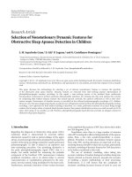
Figure 8 shows the microarray used for the evaluation
of the performance of the proposed architecture. Even if
hybridization took place only with Cy3 labelled target, the
array was scanned with both channels (red and green), and
then only the green channel was analyzed. The picture was
taken by an Agilent scanner.
Oxford has carried out hybridizations using a normal
DNA control (without the mutation) and DNAs heterozy-
gous or homozygous for the mutation. The produced
scanner data was processed by the proposed emulated
10 EURASIP Journal on Advances in Signal Processing
Figure 8: The custom microarray used for getting the data of the
performance evaluation.
0
2
4
6
8
10
12
14
16
×10
2
Intensities
Antisense-I-1
Antisense-I-3
Antisense-I-5
Antisense-I-7
Antisense-I-9
Antisense-I-11
Antisense-I-13
Probe name
3-MUTA-I
3-WTA-I
3-MUTA-I & 3-WTA-I
3-MUTA-I
3-WTA-I
Figure 9: Data analysis results of mutation 3 (antisense strand), by
the emulated architecture for wild type hybridization.
architecture on the FPGA executing the algorithmof
Section 3, and the results were used to select the appropriate
probes to interrogate the studied mutations.
The hybridization performance of a particular probe
was compared between the wild type hybridization and the
mutant hybridization. The ratio of the intensity change for
that probe was then compared to all the other probes for the
same allele present on the array.
The Mutation-3 case (antisense strand) data analysis
results for the normal DNA control hybridization is shown
in Figure 9.
The Mutation-3 case (sense strand) data analysis results
are shown in Figure 10.
From the calculations of the algorithm, antisense wild
type variation 11 and mutant type 8 (3-WTA-I-11, 3-MUTA-
0
2
4
6
8
10
12
14
16
×10
2
Intensities
Sense-I-1
Sense-I-3
Sense-I-5
Sense-I-7
Sense-I-9
Sense-I-11
Sense-I-13
Probe name
3-MUTS-I
3-WTS-I
3-MUTS-I & 3-WTS-I
3-MUTS-I
3-WTS-I
Figure 10: Data analysis results of mutation 3 (sense strand), by the
emulated architecture for wild type hybridization.
I-9) were selected as the most appropriate probes to detect
mutation 3.
The data analysis (of normalized values) was carried out
using the proposed architecture and allowed the selection of
a number of probe pairs suitable for the detection of 18 of
the 20 mutations. The total time required to produce these
results was 0.4 seconds.
These hybridizations have provided Oxford with a sig-
nificant amount of data and hopefully it will allow them to
substantially decrease the number of probes to be tested in
the future.
7. CONCLUSIONS
When scaling to multithousand sensor microarrays, the
data volume increases significantly along with the pro-
cessing time. The data analysis of the results retrieved
from microarrays requires processing power and is a time-
consuming, cumbersome, and often error-prone task. A
data processing algorithm that was presented is capable to
analyze the electronic hybridization detection sensor data of
a LoC and to decide about the existence of the interrogated
mutations. Two alternative architectures for the data analysis
were emulatied and their performance was evaluated. Data
taken from an implemented microarray of 8.500 spots was
processed by the emulated architecture, and the results are
presented.
The presented architecture is a robust data analysis cir-
cuitry for a Lab-on-Chip, which provides increased reliability
by automating spot detection and data processing by on-
chip dedicated highly integrated hardware. In particular, the
proposed data processing and analysis electronic module are
an embedded multicore reconfigurable scalable system-on-
chip architecture which is capable to process in a fraction of
nowadays processing time data of the current microarrays
but also of the future multithousand sensor microarrays.
G. Kornaros and S. Blionas 11
Hence, the integrated microsystem is ideal for a range of
applications, from small compact devices optimized for
genotyping and pharmacogenomic applications up to gene
expression analysis.
ACKNOWLEDGMENTS
The authors would like to thank Dr. Lorne Lonie, Marta
Paolucci, and Dr. Jiannis Ragoussis from the Genomics Lab
of the Wellcome Trust Centre for Human Genetics of the
Oxford University for their data to evaluate the performance
of the proposed architecture. Also they would like to
acknowledge the state of the art section that describes the
development of Paul Galvin, Marin Georghe, Mihai Dinca
of TYNDALL, Cork, Ireland, (sample preparation), Jean
Hue from LETI, Grenoble Cedex, France, (hybridization),
and Stephen Bellis from SensL, Cork, Ireland, and Stavros
Chantzandroulis from NCSR Demokritos, Agia Paraskevi
Attika, Greece, (photosensor and capacitive hybridization
electronic detection, resp.).
REFERENCES
[1] F.Model,T.K
¨
onig, C. Piepenbrock, and P. Adorj
´
an, “Statistical
process control for large scale microarray experiments,”
Bioinformatics, vol. 18, no. 90001, pp. S155–S163, 2002.
[2] N. Br
¨
andle, H. Bischof, and H. Lapp, “Robust DNA microar-
ray image analysis,” Machine Vision and Applications, vol. 15,
no. 1, pp. 11–28, 2003.
[3] S. Bellis, S. Blionas, J. Carrera, et al., “Competitive technol-
ogy approaches for electronic hybridisation detection in a
microsystem with microfluidics for diagnosis genetic tests,” in
Proceedings of the 28th Annual International Conference of the
IEEE Engineering in Medicine and Biology Society (EMBS ’06),
pp. 4103–4106, New York, NY, USA, August-September 2006.
[4] M. Bicego, M. Del Rosario Martinez, and V. Murino, “A
supervised data-driven approach for microarray spot quality
classification,” Pattern Analysis & Applications, vol. 8, no. 1-2,
pp. 181–187, 2005.
[5] V. Rodellar, F. D
´
ıaz, B. Belean, et al., “Genomic microarray
processing on a FPGA for portable remote applications,” in
Proceedings of the 3rd Southern Conference on Programmable
Logic (SPL ’07), pp. 13–18, Mar del Plata, Argentina, February
2007.
[6] F. Valafar, “Pattern recognition techniques in microarray data
analysis: a survey,” Annals of the New York Academy of Sciences,
vol. 980, no. 1, pp. 41–64, 2002.
[7] S. Mukherjee, “Classifying microarray data using support
vector machines,” in A Practical Approach to Microarray Data
Analysis, D. Berrar, W. Dubitzky, and M. Granzow, Eds.,
pp. 166–185, Kluwer Academic Publishers, Dordrecht, The
Netherlands, 2003.
[8] R. B. Fair, A. Khlystov, V. Srinivasan, V. K. Pamula, and K. N.
Weaver, “Integrated chemical/biochemical sample collection,
pre-concentration, and analysis on a digital microfluidic lab-
on-a-chip platform,” in Lab-on-a-Chip: Platforms, Devices,
and Applications, L. A. Smith and D. Sobek, Eds., vol. 5591
of Proceedings of SPIE, pp. 113–124, Philadelphia, Pa, USA,
October 2004.
[9] T. Xu and K. Chakrabarty, “A cross-referencing-based
droplet manipulation method for high-throughput and pin-
constrained digital microfluidic arrays,” in Proceedings of the
Design, Automation & Test in Europe Conference & Exhibition
(DATE ’07), pp. 1–6, Nice, France, April 2007.
[10] W. L. Hwang, F. Su, and K. Chakrabarty, “Automated design
of pin-constrained digital microfluidic arrays for lab-on-a-
chip applications,” in Proceedings of the 43rd ACM/IEEE Design
Automation Conference (DAC ’06), pp. 925–930, San Francisco,
Calif, USA, July 2006.
[11] I. Ragoussis, M. Paolucci, and L. Lornie, “D5.1Development
of a robust mutation, detection protocol,” Micro2DNA ICT-
027333-STP EC project, July 2007.
[12] C. Zhang, J. Xu, W. Ma, and W. Zheng, “PCR microfluidic
devices for DNA amplification,” Biotechnology Advances, vol.
24, no. 3, pp. 243–284, 2006.
[13] A C. Syv
¨
anen, “Accessing genetic variation: genotyping single
nucleotide polymorphisms,” Nature Reviews Genetics, vol. 2,
no. 12, pp. 930–942, 2001.
[14]D.J.Cutler,M.E.Zwick,M.M.Carrasquillo,etal.,
“High-throughput variation detection and genotyping using
microarrays,” Genome Research, vol. 11, no. 11, pp. 1913–1925,
2001.
[15] T. R. Hughes, M. Mao, A. R. Jones, et al., “Expression profiling
using microarrays fabricated by an ink-jet oligonucleotide
synthesizer,” Nature Biotechnology, vol. 19, no. 4, pp. 342–347,
2001.
[16] J. C. Jackson, A. P. Morrison, D. Phelan, and A. Mathew-
son, “A novel silicon Geiger-mode avalanche photodiode,”
in Proceedings of the IEEE International Electron Devices
Meeting (IEDM ’02), pp. 797–800, San Francisco, Calif, USA,
December 2002.
[17] Y.H.Yang,M.J.Buckley,S.Dudoit,andT.P.Speed,“Compar-
ison of methods for image analysis on cDNA microarray data,”
Journal of Computational and Graphical Statistics, vol. 11, no.
1, pp. 108–136, 2002.
[18] G. Kornaros, et al., “Architecture of a consumer lab-on-
chip for pharmacogenomics,” in Proceedings of the IEEE
International Conference on Consumer Electroncs (ICCE ’08),
Las Vegas, USA, January 2008.