Báo cáo hóa học: " Research Article A Sharing-Based Fragile Watermarking Method for Authentication and Self-Recovery of Image Tampering" potx
Bạn đang xem bản rút gọn của tài liệu. Xem và tải ngay bản đầy đủ của tài liệu tại đây (4.63 MB, 17 trang )
Hindawi Publishing Corporation
EURASIP Journal on Advances in Signal Processing
Volume 2008, Article ID 852697, 15 pages
doi:10.1155/2008/852697
Research Article
Protection of Video Packets over a Wireless
Rayleigh Fading Link: FEC versus ARQ
Julie Neckebroek, Frederik Vanhaverbeke, Danny De Vleeschauwer, and Marc Moeneclaey
Department of Telecommunications and Information Processing (TELIN), Ghent University,
Sint-Pietersnieuwstraat 41, 9000 Gent, Belgium
Correspondence should be addressed to Julie Neckebroek,
Received 1 October 2007; Revised 25 March 2008; Accepted 8 May 2008
Recommended by David Bull
Video content can be provided to an end user by transmitting video data as a sequence of internet protocol (IP) packets over the
network. When the network contains a wireless link, packet erasures occur because of occasional deep fades. In order to maintain
asufficient video quality at the end user, video packets must be protected against erasures by means of a suitable form of error
control. In this contribution, we investigate two types of error control: (1) forward error correction (FEC), which involves the
transmission of parity packets that enables recovery of a limited number of erased video packets, and (2) the use of an automatic
repeat request (ARQ) protocol, where the receiver requests the retransmission of video packets that have been erased. We point
out that FEC and ARQ considerably reduce the probability of unrecoverable packet loss, because both error control techniques
provide a diversity gain, as compared to the case where no protection against erasures is applied. We derive a simple analytical
expression for the diversity gain resulting from FEC or ARQ, in terms of the channel coherence time, the allowable latency, and
(for FEC) the allowable overhead or (for ARQ) the time interval between (re)transmissions of copies of a same packet. In the case
of HDTV transmission over a 60 GHz indoor wireless link, ARQ happens to outperform FEC.
Copyright © 2008 Julie Neckebroek et al. This is an open access article distributed under the Creative Commons Attribution
License, which permits unrestricted use, distribution, and reproduction in any medium, provided the original work is properly
cited.
1. INTRODUCTION
The internet protocol (IP) allows the provision of a mix of
multimedia services (video, audio, voice, data, gaming, etc.)
to an end user, by breaking up the bitstreams generated by
the various services into IP packets and sending these packets
over the network. In this contribution, we consider the
delivery of these multimedia services via a wireless channel,
and focus on the reliability of the received video data.
The occurrence of fading on wireless channels makes
reliable transmission a difficult task, because occasional deep
fades give rise to bursts of bit errors at the receiver. IP packets
affected by bit errors are erased at the receiver, yielding lost
packets at the destination. These lost packets are likely to
cause visual distortions when viewing the video content at
the destination. Hence, in order to obtain a sufficient quality
of experience (QoE) it is imperative to limit the video packet
loss rate.
In addition, the frequency selectivity of the wireless
channel distorts the transmitted signal. In order to cope with
frequency selectivity, we resort to a multicarrier modulation
(orthogonal frequency division multiplexing (OFDM)) [1],
which turns the frequency-selective channel into a number
of parallel frequency-flat channels.
In order to alleviate the damaging impact of fading, one
can reduce the probability of bit errors by means of coding
on the physical (PHY) layer. Not only the video, but also the
other services that are provided via the same wireless link
stand to benefit from this coding. In this contribution, we
restrict our attention to orthogonal space-time block codes
[2–4], for which the optimum decoding reduces to linear
processing and simple symbol-by-symbol detection. When
this PHY layer coding is not sufficient to yield a satisfactory
QoE related to video, additional protection of the video
packets must be envisaged.
In order to provide additional protection of the video
packets against erasures, one can resort to forward error
correction (FEC) coding [5, 6]ortoautomaticrepeat
request (ARQ) protocols [7, 8]; these techniques involve the
transmission of redundant packets (in addition to the video
information packets) or sending a request for retransmitting
erased video packets, respectively. Various proposals have
2 EURASIP Journal on Advances in Signal Processing
been formulated for protecting packets against erasures by
means of FEC [9–12]; in this contribution we select reed-
solomon (RS) codes, because they are able to recover the
maximum possible number of erasures for a given transmis-
sion overhead [5, 13]. As far as ARQ protocols are concerned,
we consider selective repeat (SR) ARQ, which yields the
minimum transmission overhead [7, 8]. It is important to
keep in mind, however, that these techniques come with
a cost. First, both FEC and ARQ introduce transmission
overhead (usually higher for FEC than for ARQ) and some
latency. Second, there is a complexity increase: ARQ requires
a retransmission buffer and a return channel from the
receiver to the retransmitting network node, and FEC needs
additional encoding/decoding operations.
In this contribution, we investigate to what extent the
combination of the RS code or the SR ARQ protocol with
the space-time PHY layer code improves the reliability
of the video transmission over a wireless channel subject
to Rayleigh fading. The paper is organized as follows. In
Section 2, we introduce some basic concepts about video
compression and transmission over an IP network, and
describe the space-time coding on the PHY layer. We
detail in Section 3 the RS erasure coding and the SR ARQ
protocol that are used as additional protection of the video
packets against erasures. We provide in Section 4 the error
performance analysis for various scenarios, involving space-
time coding or no coding on the PHY layer, with or without
protection (RS coding or SR ARQ) of the video packets.
In Section 5, we present numerical results, including a case
study pertaining to HDTV transmission over a 60 GHz
indoor wireless link. Finally, in Section 6 conclusions are
drawn regarding system performance and complexity, and
some generalizations of the considered assumptions are
briefly discussed. A major conclusion is that RS erasure
coding and SR ARQ yield the same maximum possible
diversity gain, which is determined by the ratio of the
allowed latency and the channel coherence time; however,
this maximum cannot be achieved because of practical
constraints on the allowed overhead (RS erasure coding) or
when the time interval between retransmissions exceeds the
channel coherence time (SR ARQ).
2. VIDEO SOURCE CODING AND TRANSMISSION
In this section, we describe the video packet transmission
from the video server to the end user. First, the video source
coding method is considered. Next, the different layers in
the protocol stack of the OSI-model, that are relevant to this
research, are presented.
2.1. Video source coding
The video stream is encoded (compressed) according to
the MPEG-2 standard [14, 15], which is commonly used
as the format for digital television. The Video section
of MPEG-2 (part 2) is designed to compress the video
stream through appropriate coding by exploiting the existing
redundancy in space and time. Uncompressed video can
be seen as a sequence of picture frames (e.g., 25 frames
per second). Typically, the scenes in successive pictures are
very similar. One can take advantage of this similarity to
compress the video into three types of frames: intracoded
frames (I-frames), predictive-coded frames (P-frames), and
bidirectional-predictive-coded frames (B-frames).
An I-frame is a compressed version of a single uncom-
pressed frame. The compression is achieved by exploiting
the spatial redundancy in the image and the insensitivity of
the human eye to certain changes in the image. P-frames,
on the other hand, achieve a higher compression because
they take advantage of the resemblence between the picture
in the current frame and the picture in the previous I- or
P-frame. B-frames are compressed by exploiting both the
picture in the preceding I- or P-frame as well as the picture in
the following I- or P-frame. These B-frames achieve an even
higher compression rate. A commonly used frame pattern is
IBBPBBPBBPBB, called a group of pictures (GOPs), which
consists of 12 compressed frames and which is repeated. Such
a GOP has a duration of 480 milliseconds (25 frames per
second).
As the different types of frames achieve different com-
pression rates, their resulting sizes, measured in bits, are not
equal. I-frames are larger than P-frames, which in turn are
larger than B-frames. Their exact sizes depend on the video
content. Typically, the average sizes of I- and P-frames are
about 6 and 2 times the average size of a B-frame.
Because of the interdependence of the compressed
frames, error propagation occurs: an erroneous I- or P-frame
results in errors (after decoding) in the 2 preceding B-frames
and in all following frames up to (but not including) the next
I-frame. Hence, when an I- or P-frame in a GOP is affected
by unrecoverable transmission errors, a visual distortion is
likely to occur when viewing the video content. Errors in a B-
frame do not propagate to other frames. Hence, when only a
B-frame in a GOP is affected by unrecoverable transmission
errors, it is possible that no visual distortion occurs through
the use of error concealment techniques that exploit the
similarity between the erroneous B-frame and surrounding
frames.
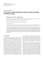
2.2. Protocol stack
Let us consider the case where video data is sent from
the video server to the end user, as shown in Figure 1.
A source, the video server, broadcasts the video data. Via
an aggregation network, this video data reaches a digital
subscriber line access multiplexer (DSLAM). The DSLAM
sends the data related to a mix of services (video, audio,
voice, data, gaming, etc.), over a digital subscriber line (DSL)
[16] to the user home gateway (HG). From the HG, the
video data is sent through a wireless LAN to the set top
box (STB). Figure 1 also displays the different layers of the
protocol stack, that are involved in the operation of each
of the network nodes. The network nodes are not able to
process information from other layers.
2.3. Application layer
The system section of MPEG-2 (part 1) [15] describes
how MPEG-compressed video and audio data streams
Julie Neckebroek et al. 3
Wireless
connection
Aggregation
network
Video
server
DSLAM
DSL lines
No erasures
HG+transmitter
STB+TV
Rayleigh fading
RTP
UDP
IP
MAC
PHY
IP
MAC
PHY
IP
MAC
PHY
RTP
UDP
IP
MAC
PHY
Figure 1: Concatenation of DSL connection and wireless connec-
tion (DSLAM
= digital subscriber line access multiplexer, HG =
home gateway, STB = set-top box).
(along with other data, such as teletext, elementary stream
identifiers) are multiplexed together to form a single data
stream. Basically, the resulting transport stream (TS) consists
of a sequence of MPEG-TS packets, that consist of 188 bytes
each (including a 4-byte header).
2.4. Session layer
The real-time transport protocol (RTP) [17]isusedtodeliver
audio and video over the Internet. The RTP packets are
filled with an integer number of TS packets. In commercial
equipment, an RTP packet typically contains 7 TS packets,
which is the maximum number of TS packets that fits inside
an Ethernet frame (data link layer). The header of an RTP
packet contains, among other things, a sequence number
and a time stamp. This allows the detection of missing
or out-of-order delivery of RTP packets and to perform
synchronization, respectively. The header inserted by this
protocol is 12 bytes long.
2.5. Transport layer and network layer
The user datagram protocol (UDP) is used on the transport
layer to deliver the RTP packets. UDP is well suited for
time-sensitive applications that prefer dropped packets to
excessively delayed packets.
The UDP packets are passed to the underlying layer, the
network layer. This layer uses the IP protocol to deliver the
data from source to destination.
2.6. Data link layer
On the medium access control (MAC) sublayer of the data
link layer, a header and trailer are added; the latter contains
a cyclic redundancy check (CRC). This CRC allows the
detection of packets that are corrupted by transmission
errors; corrupted packets are not forwarded to the network
layer, but are discarded (“erased”). We assume that no ARQ
is applied on the MAC layer; the effect of ARQ on the MAC
layer is briefly discussed in Section 6.
The structure of a data-link-layer packet is visualized in
Figure 2. The packet contains 7 MPEG-TS packets, and the
7MPEG-TSpackets
MAC
header
IP
header
UDP
header
RTP
header
MAC
trailer
Figure 2: The video data is nested in a structure of packets, each
packet and corresponding header results from a different layer in
the protocol stack.
various headers/trailers that have been added by the different
layers in the protocol stack.
2.7. Physical layer
As far as the physical (PHY) layer is concerned, we only
consider the wireless link between the HG and the STB.
On the PHY layer of the HG transmitter, the L bits to be
sent for every data-link-layer packet are mapped onto an M-
point signal constellation. The resulting M-ary data symbols
are transmitted at a rate R
s
(in symbols per second) over
the wireless channel; hence the duration of a packet equals
L/(R
s
log
2
(M)). The transmission makes use of orthogonal
frequency-division multiplexing (OFDM) [1]. The sequence
of data symbols at rate R
s
is demultiplexed into N
c
parallel
symbol streams, each of rate R
s
/N
c
. These N
c
symbol streams
are modulated onto N
c
distinct subcarriers, that have a
frequency separation of (slightly more than) R
s
/N
c
,and
the sum of these modulated subcarriers is transmitted. The
transmitted signal can be viewed as a sequence of OFDM
blocks. As shown in Figure 3, an OFDM block has a duration
of N
c
/R
s
, and contains N
c
data symbols (i.e., one symbol
on each of the N
c
subcarriers). The bandwidth occupied by
the resulting transmitted signal is (slightly more than) R
s
.
The transmission of an L-bit packet involves L/(N
c
log
2
(M))
OFDM blocks. Typically, the number N
c
ofcarriersison
the order of 100 to 1000. Because of the large number of
subcarriers, OFDM turns the wireless fading channel into a
set of N
c
flat-fading parallel channels.
For each subcarrier, the fading gain is assumed to be
piecewise constant over time; the fading gain does not change
over a time interval equal to the channel coherence time T
coh
,
and is statistically independent of the fading gain in other
intervals of duration T
coh
. During an interval T
coh
,several
packets are transmitted, as indicated in Figure 4.Packets
from other applications are located in between the packets
with video data.
On the PHY layer of the STB receiver, the M-ary data
symbols are detected, and demapped to bits. On the MAC
sublayer, the recovered bits are grouped into packets of size L,
and error detection based on the CRC is performed. When an
error is detected, the packet is erased; otherwise, the packet
is passed to the higher layers.
Because of fading, the received signal is occasionally
strongly attenuated. To alleviate the damaging impact of
fading on the detection of the M-ary data symbols, we
consider the use of multiple transmit and receive antennas.
A multiple-input multiple-output (MIMO) system with N
t
transmit and N
r
receive antennas allows the introduction
4 EURASIP Journal on Advances in Signal Processing
Frequency
Symbol 1
Symbol 2
R
s
/N
c
R
s
.
.
.
Symbol N
c
N
c
/R
s
Time
Figure 3: Representation of an OFDM block in time and frequency.
Video packets
L bits
L/(R
s
log
2
(M))
Fading gain
Deep fade
Time
Coherence time
= T
coh
Time
Figure 4: Video packet stream and fading gain versus time; in
this example, 2 video packets are transmitted during the channel
coherence time, in which case a packet group consists of 2 packets.
of space-time coding [2–4]. Whereas an uncoded single-
input single-output (SISO) system, that is, N
t
= N
r
=
1, provides only one wireless link between the HG and
the STB, the number of wireless links provided by an
orthogonal space-time block-coded (OSTBC) MIMO system
equals N
r
N
t
. As compared to an SISO system, the larger
number of links resulting from OSTBC MIMO gives rise
to a considerably higher robustness against fading, and a
much better error performance. Using an OSTBC MIMO
system does not require additional bandwidth as compared
to the SISO system, but comes at a substantial hardware
cost that increases with the number of antennas. The space-
time coding only marginally increases the latency. Optimum
decoding of OSTBC MIMO reduces to linear processing and
simple symbol-by-symbol detection at the receiver.
In this paper, we will consider the Alamouti space-
time code [2], which requires 2 transmit antennas (and
an arbitrary number N
r
of receive antennas). Denoting by
s
n
(t) the signal that corresponds to the nth OFDM block,
Alamouti space-time coding involves the transmission of
two OFDM blocks during two consecutive intervals (each of
duration N
c
/R
s
) on two antennas, according to the following
scheme:
interval 2i: s
2i
(t) (on antenna 1)
s
2i+1
(t) (on antenna 2),
interval 2i +1:
−(s
2i+1
(t))
∗
(on antenna 1)
(s
2i
(t))
∗
(on antenna 2),
(1)
where ()
∗
denotes complex conjugate. Hence, each OFDM
block s
n
(t) reaches the receiver via 2N
r
wireless links.
3. ADDITIONAL PROTECTION OF THE VIDEO DATA
As mentioned before, packets yielding an erroneous check-
sum are discarded (erased) on the MAC layer, because
they have been affected by transmission errors; the other
packets are assumed to be received correctly. Because of
video packet erasures, visual distortions may occur when
viewing the received video content. In order to guarantee
asufficient QoE to the end user, the rate of video packet
erasures should be limited. When the packet erasure rate
caused by transmission errors on the wireless link is too
large, additional measures are needed to recover erased video
packets. In this contribution, we consider the combination
of a PHY layer with either no coding or Alamouti space-time
coding with 1 or 2 receive antennas, and additional packet
protection by means of either RS erasure coding or SR ARQ.
3.1. RS erasure coding
The RS code is defined over the Galois field GF(2
q
), which
implies that an RS code symbol consists of q bits; typically,
q
= 8. (The RS code symbols are not to be confused with
the transmitted data symbols; the former belong to GF(2
q
),
whereas the latter belong to an M-point signal constellation.)
In the sequel, a video information packet refers to the MPEG-
TS payload (i.e., 7 MPEG-TS packets) of the packet as shown
in Figure 2.PergroupofK of these video information
packets, we transmit N
− K parity packets. This results in
apacketcodewordofN packets. The parity packets are
constructed such that taking from each packet the ith block
of q bits yields an RS(N, K)codeword,foralli
= 1, 2, , L/q.
This construction is illustrated in Figure 5. Hence, when e
packets from the packet codeword are erased, each of the L/q
RScodewordsisaffected by exactly e symbol erasures.
The RS(N,K) code is known to be maximum distance
separable (MDS), that is, the code can recover up to N
− K
erasures, which cannot be outperformed by any other code
with the same number N
− K of parity symbols (Note that
a receiver without an RS decoder can still process the packet
stream by simply ignoring the parity packets, at the expense
of a performance degradation as compared to a receiver with
an RS decoder.) [5, 13]. When the number of erasures is
larger than N
− K, erasure decoding fails and unrecoverable
packet loss occurs.
The introduction of erasure coding yields an increase of
both overhead and latency.
(i) Using an (N, K) block code gives rise to a trans-
mission overhead ovh given by ovh
= (N −K)/K,
Julie Neckebroek et al. 5
because for each K information packets, N − K
additional packets must be transmitted. Hence,
denoting by R
pack
(in packets per second) the rate
of information packets, the packet transmission rate
equals (N/K)R
pack
. This indicates that because of
the coding the fraction of time during which the
channel is used for video transmission is increased by
afactorN/K, leaving less room for the transmission
of packets from other applications.
(ii) When at most N
− K packets are erased, they can
be recovered by means of the RS(N,K)code.To
perform erasure decoding, at least K packets must
be received correctly. Hence, the RS decoder might
need to wait until all N packets of the codeword
are received, before the erasure decoding can start.
Hence, using the (N,K) block code introduces a
maximum additional latency T
lat
which equals the
duration K/R
pack
of a packet codeword. Increasing
the latency gives rise to a larger zapping delay,
which might unfavorably affect the user’s QoE. (The
zapping delay is the time that elapses between giving
the command to change the TV channel and the
appearance of the new TV channel on the screen
[18].)
Considering the above, the code parameters N and K
should be selected such that the overhead and latency are
limited to reasonable values.
It is convenient that the parity packets are generated by
the video server, as this is the only network node (besides
the STB of the end user) that has access to the video data. In
principle, parity packets could instead be generated by the
DSLAM or the HG. However, this would require that the
DSLAM or the HG has access to the higher protocol layers
(beyond IP), which would increase their complexity and cost.
3.2. Selective repeat ARQ
As far as ARQ is concerned, we consider an SR retrans-
mission protocol. The STB receiver sends a retransmission
request for each of the erased video packets, and only
copies of the erased packets are retransmitted. To limit the
round-trip delay, we assume that retransmissions occur from
either the DSLAM or the HG. Of course, the functionality
of the retransmitting network node needs to be extended
beyond the IP layer, in order to be capable of recognizing
retransmission requests related to specific video packets;
in addition, this node must have a retransmission buffer
containing video packets that have not yet been correctly
received. Augmenting the functionality of the DSLAM or HG
increases their complexity and cost. As the HG is a consumer
product, the DSLAM appears to be the economically justified
choice for operating as the retransmitting node. However, the
HG offers the shorter round-trip delay.
Upon receiving a retransmission request, the retrans-
mitting network node sends a copy of the packet involved.
Retransmissions are scheduled such that the time interval
T
retr
between the (re)transmission instants of copies of the
same packet is not less than the channel coherence time
T
coh
. This way, the different copies experience statistically
independent fading. When one would select T
retr
<T
coh
, the
retransmission of a packet that has been erased because of a
deep fade is experiencing the same deep fade, and therefore
is likely to be erased as well. Such retransmissions should be
avoided, as they are not useful, but rather contribute to the
transmission overhead.
The minimum possible time interval T
retr, min
between
(re)transmission instants of the same packet is the sum
of the packet duration L/(R
s
log
2
(M)) and the round-trip
delay T
RT
; the latter is the sum of the two-way propagation
delay, the duration of the acknowledgment message, and the
processing delays at the receiver and the transmitter [7, 8].
We select T
retr
= max(T
retr, min
, T
coh
). When T
retr, min
>T
coh
,
this yields T
retr
= T
retr, min
: the interval between transmission
instants is the shortest possible, and (re)transmitted copies
of the same packet experience-independent fading. When
T
retr, min
≤ T
coh
,wegetT
retr
= T
coh
: the retransmission
instant is deliberately delayed by an amount (T
coh
−T
retr, min
)
with respect to the earliest possible retransmision instant, in
order that the (re)transmitted copies of the same packet are
affected by independent fading gains.
Since each retransmission gives rise to a latency of T
retr
,
the maximum number N
retr
of allowed retransmissions per
packet is given by N
retr
=T
lat
/T
retr
, in order that the total
latency caused by the SR ARQ protocol does not exceed T
lat
.
4. SYSTEM ANALYSIS
In this section, we present the analysis of the system under
study. We first investigate the PHY layer, followed by the
additional packet protection by means of RS erasure coding
or SR ARQ. As a performance measure, we consider the
average number of GOPs that are affected by irrecoverable
packet loss, over a reference time interval of 12 hours. Finally,
analytical results regarding RS erasure coding and SR ARQ
are compared.
4.1. PHY layer
We consider the cases of uncoded SISO transmission, and
Alamouti orthogonal space-time coding (2 transmit anten-
nas) with 1 or 2 receive antennas. The probability P
bit
(x),
that a bit is received in error, depends on the instantaneous
channel state x. The channel state x is the sum of the squared
fading gains that are involved in the transmission of the
considered bit (1 fading gain for SISO, and 2 or 4 fading
gains for Alamouti with 1 or 2 receive antennas). Limiting
our attention to QPSK transmission, P
bit
(x)isgivenby[2, 6]
P
bit
(x) =
⎧
⎪
⎪
⎪
⎪
⎪
⎨
⎪
⎪
⎪
⎪
⎪
⎩
Q
2E
b
x
N
0
uncoded SISO,
Q
E
b
x
N
0
Alamouti,
(2)
where
Q(v)
=
1
√
2π
+∞
v
exp
−
u
2
2
du (3)
6 EURASIP Journal on Advances in Signal Processing
is the complement of the cumulative distribution function of
a zero-mean unit-variance Gaussian random variable. In (2),
E
b
denotes the transmitted energy per bit of the video packet,
and N
0
is the one-sided power spectral density of the noise at
the receiver. P
bit
(x)equals1/2forx = 0, and converges to 0
when x
→∞; the larger E
b
/N
0
is, the faster this convergence
occurs. When the fading gains are normalized such that the
average energy per bit at each receive antenna also equals E
b
,
the probability density function p(x) of the channel state is
given by [6]
p(x)
=
x
D−1
exp(−x)
(D − 1)!
,(4)
with D
= 1 for uncoded SISO and D = 2orD = 4for
Alamouti with N
r
= 1orN
r
= 2. The quantity D is the
diversity provided by the PHY layer; basically, D equals the
number of physical links between the transmitter and the
receiver that are exploited by the transmission scheme. As
we will shortly demonstrate, the error performance improves
with increasing D; this is intuitively clear, because all D links
must fail for a packet erasure to occur.
From (2), the packet erasure probability P
pack
(x) condi-
tioned on x equals
P
pack
(x) = 1 −
1 − P
bit
(x)
L
. (5)
To obtain (5), we have assumed that all N
c
subcarriers of the
OFDM signal experience the same value of the channel state
x, and have taken into account that the packet duration is
less than the channel coherence time, so that the channel
state is the same for all L bits of a packet. The effect of
relaxing this assumption is briefly discussed in Section 6.For
x
= 0, P
pack
(x)and1− P
pack
(x)equal1− 2
−L
and 2
−L
,
respectively. For x
→∞, P
pack
(x)and1− P
pack
(x)converge
to zero and to one, respectively; the speed of convergence
increases with increasing E
b
/N
0
. Finally, note from (2) that
P
bit
(x)andP
pack
(x)dependonx and E
b
/N
0
only through the
variable y
= xE
b
/N
0
.
Before we consider in the next subsections the cases
where RS erasure coding or SR ARQ is used in order
to recover erased packets, we now investigate the system
performance under the assumption that no such error
controlmeasuresaretaken.
We defi ne a packet group as the set of packets that
are transmitted consecutively in time during an interval
of duration T
coh
over which the fading is constant. We
denote by N
coh
the number of packets transmitted during
the interval T
coh
. For the example shown in Figure 4,wehave
N
coh
= 2. As we consider the case where only information
packets and no parity packets are transmitted, we have
N
coh
=T
coh
R
pack
. The probability P
group
(e) that e packets
are erased within a packet group of size N
coh
,irrespectiveof
the channel state, is given by
P
group
(e) =
N
coh
!
e!(N
coh
−e)!
×
+∞
0
P
e
pack
(x)
1−P
pack
(x)
N
coh
−e
p(x)dx,
e
= 0, , N
coh
.
(6)
Considering the behavior of 1
−P
pack
(x), P
group
(0) converges
to 1 for large E
b
/N
0
. For large E
b
/N
0
and e>0, P
e
pack
(x)goes
to zero much faster than p(x) for increasing x, so that the
factor exp(
−x)in(4) can be approximated as exp(−x) ≈ 1.
Using the approximation in (6) along with the substitution
F
E
b
x
N
0
=
N
coh
!
e!(N
coh
− e)!
P
e
pack
(x)
1 − P
pack
(x)
N
coh
−e
,
(7)
we obtain, for high E
b
/N
0
,
P
group
(e) ≈
+∞
0
F
E
b
x
N
0
x
D−1
(D − 1)!
dx
=
E
b
N
0
−D
+∞
0
F(y)
y
D−1
(D − 1)!
dy, e
= 1, , N
coh
.
(8)
Taking into account that F(y)isnotafunctionofE
b
/N
0
,we
have P
group
(e) ∝ (E
b
/N
0
)
−D
for e>0.
Let us now compute the probability P
GOP
that a GOP is
affected by unrecoverable packet loss. As no measures are
taken to recover erased packets, each erased packet is lost.
Denoting by T
GOP
and N
GOP
the duration of one GOP and
the number of packet groups that fit within the duration of
one GOP, respectively, we have T
GOP
= N
GOP
N
coh
/R
pack
,and
P
GOP
= 1 −
P
group
(0)
N
GOP
= 1 −
1 −
N
coh
e=1
P
group
(e)
N
GOP
=
N
GOP
i=1
N
GOP
!(−1)
i−1
i!(N
GOP
− i)!
N
coh
e=1
P
group
(e)
i
≈ N
GOP
N
coh
e=1
P
group
(e)
= N
GOP
1 − P
group
(0)
.
(9)
The approximation in (9) corresponds to keeping only the
term with i
= 1, which is the dominating term at high E
b
/N
0
.
Hence, for large E
b
/N
0
,weobtainP
GOP
∝ (E
b
/N
0
)
−D
. This
illustrates the impact of the PHY layer diversity D: the larger
D, the smaller the probability that a GOP is affected by packet
erasures.
From (9), we compute the average number E[#GOP
unrec
]
of GOPs that are affected by unrecoverable packet loss in
a reference interval T
ref
of 12 hours. Denoting by N
ref
the
number of GOP intervals in T
ref
,wehaveT
ref
= N
ref
T
GOP
=
N
ref
N
GOP
T
coh
.Hence,
E
#GOP
unrec
=
N
ref
P
GOP
≈ N
ref
N
GOP
1 − P
group
(0)
=
T
ref
T
coh
1 − P
group
(0)
.
(10)
Julie Neckebroek et al. 7
The approximation in (10)holdsforlargeE
b
/N
0
. Note that,
at high E
b
/N
0
, E[#GOP
unrec
] is independent of the GOP
duration, and proportional to (E
b
/N
0
)
−D
.
4.2. Packet protection by means of RS erasure coding
Now we consider the case where (N
− K) parity packets are
added to K information packets, yielding a (N, K)RSpacket
codeword. The number N
coh
of packets transmitted during
the interval T
coh
is now given by N
coh
=(N/K)T
coh
R
pack
,
which denotes the size of a packet group. We assume that the
N packets of the packet codeword are distributed over N
group
packet groups, to which we associate the indices 1, 2, and
N
group
.Wedenotebye
n
the number of erased packets in
the packet group with index n (n
= 1, , N
group
), and
introduce the vector e
= (e
1
, , e
N
group
). We define by Pr(e)
the probability that the number of erased packets in the
groups with indices 1, 2, and N
group
equals e
1
, e
2
, and
e
N
group
, respectively. Assume for simplicity that N is an integer
multiple of N
coh
and that the first packet of the codeword is
also the first packet of a packet group; in this case, we have
N
group
= N/N
coh
, and each of the packet groups contains
exactly N
coh
packets from the considered codeword. Taking
into account that erasures in different packet groups are
statistically independent, we obtain
Pr(e)
=
N
group
n=1
P
group
e
n
, (11)
where P
group
(e)isgivenby(6), but with N
coh
=
(N/K)T
coh
R
pack
. When N is not an integer multiple of N
coh
and/or the first packet of the codeword is not the first packet
ofagroup,anedgeeffect occurs: we get N
group
=N/N
coh
or N
group
=N/N
coh
+ 1, depending on the position of
the first packet of the codeword within its packet group; for
example, Figure 6 shows a situation with N
= 5, N
coh
=
3, and N
group
= 3. Then (11) must be slightly modified
by taking into account that the packet groups with indices
1andN
group
might contain fewer than N
coh
packets from
the considered codeword. Recalling that, for high E
b
/N
0
,
P
group
(e) ∝ (E
b
/N
0
)
−D
for e>0andP
group
(0) ≈ 1; it follows
from (11) that Pr(e)
∝ (E
b
/N
0
)
−nD
with n denoting the
number of nonzero entries of e.
From (11), the probability P
RS
(e
tot
) that e
tot
erasures
occur in the packet codeword is given by
P
RS
e
tot
=
e
1
+e
2
+···+e
N
group
=e
tot
Pr(e). (12)
Finally, the probability Pr(decoding failure) that the erasures
cannot be recovered by the RS decoder (because e
tot
is larger
than N
− K)becomes
Pr[decoding failure]
=
N
e
tot
=N−K+1
P
RS
e
tot
=
1 −
N−K
e
tot
=0
P
RS
e
tot
.
(13)
In order to obtain at least (N
− K + 1) erasures in the
codeword, at least γ
RS
=(N − K +1)/N
coh
packet groups
must contain erased packets; this implies that the vectors e in
(12)musthaveatleastγ
RS
nonzero entries. Hence, for large
E
b
/N
0
, Pr(decoding failure) is proportional to (E
b
/N
0
)
−γ
RS
D
.
Taking into account that ovh
= (N − K)/K, T
lat
= K/R
pack
and N
coh
=(N/K)T
coh
R
pack
=NT
coh
/T
lat
≈NT
coh
/T
lat
,
γ
RS
can be expressed as
γ
RS
=
N −K +1
N
coh
≈
N −K
N
coh
≈
ovh
1+ovh
·
T
lat
T
coh
.
(14)
Note that γ
RS
is an increasing function of both ovh and T
lat
.
Now we consider the probability P
GOP
that a GOP is
affected by an unrecoverable packet loss. Denoting by N
RS
the number of packet codewords in one GOP interval T
GOP
,
we have T
GOP
= N
RS
K/R
pack
,and
P
GOP
= 1 −(1 −Pr[decoding failure])
N
RS
≈ N
RS
Pr[decoding failure].
(15)
Similary, the average number of GOPs that are affected by
unrecoverable packet loss during a reference period T
ref
of 12
hoursisgivenby
E[#GOP
unrec
] = N
ref
P
GOP
≈ N
ref
N
RS
Pr[decoding failure]
=
T
ref
T
lat
Pr[decoding failure],
(16)
where T
ref
= N
ref
T
GOP
= N
ref
N
RS
T
lat
. The approximations in
(15)and(16) are valid for large E
b
/N
0
.Wededucefrom(15)
and (16) that both P
GOP
and E[#GOP
unrec
] are proportional
to (E
b
/N
0
)
−γ
RS
D
. Hence, as compared to the case where no
erasure coding is used, the effect of the RS(N,K)codeis
to increase the diversity order from D to γ
RS
D:erasure
coding introduces a diversity gain of γ
RS
. According to (14),
atradeoff exists between the achievable diversity gain and
the allowable overhead and latency: the smaller the allowable
overhead and latency, the smaller the achievable diversity
gain.
4.3. Packet protection by means of
selective repeat ARQ
With the proposed retransmission strategy, a packet will be
lost definitively when it has been erased during the first
transmission and during N
retr
successive retransmissions.
The probability P
ARQ, unrec
(x) of this event is given by
P
ARQ, unrec
(x) =
N
retr
i=0
P
pack
(x
i
), (17)
where P
pack
(x) is the packet erasure probability correspond-
ing to a channel state x (see (5)), and x
= (x
0
, , x
N
retr, max
)
contains the values of the channel state at the first trans-
mission and the subsequent N
retr
retransmissions of the
considered packet. The probability P
group, unrec
(x) that at least
8 EURASIP Journal on Advances in Signal Processing
1symbol= q bits
Packet 1:
Packet 2:
Packet K
− 2:
Packet K
− 1:
Packet K:
Packet N:
···
···
RS codeword
···
···
···
···
···
···
···
K
information
packets
N
− K
parity packets
Figure 5: Construction of a packet codeword.
one packet from a packet group of N
coh
=T
coh
R
pack
packets (which all experience the same channel state) is
erased definitively is given by
P
group, unrec
(x) = 1 − (1 −P
ARQ, unrec
(x))
N
coh
=
N
coh
j=1
N
coh
!
j!(N
coh
− j)!
(
−1)
j−1
P
j
ARQ, unrec
(x).
(18)
Averaging P
group, unrec
(x) over the channel gain statistics
yields the probability P
group, unrec
that at least one packet in
a packet group is definitively lost, irrespective of the channel
state values:
P
group, unrec
=
N
coh
j=1
N
coh
!
j!(N
coh
− j)!
(
−1)
j−1
E[P
j
ARQ, eras
(x)]
=
N
coh
j=1
N
coh
!
j!(N
coh
− j)!
(
−1)
j−1
E
N
retr
i=0
P
j
pack
(x
i
)
=
N
coh
j=1
N
coh
!
j!(N
coh
− j)!
(
−1)
j−1
(E[P
j
pack
(x)])
N
retr
+1
(19)
with
E[P
j
pack
(x)] =
+∞
0
P
j
pack
(x)p(x)dx (20)
and where p(x)isgivenby(4). For large E
b
/N
0
,wehave
E[P
j
pack
(x)] ∝ (E
b
/N
0
)
−D
, so that P
group, unrec
is proportional
to (E
b
/N
0
)
−(1+N
retr
)D
.
Following the same reasoning as in Section 4.1, the
quantities P
GOP
and E[#GOP
unrec
]aregivenby
P
GOP
= 1 −(1 −P
group, unrec
)
N
GOP
≈ N
GOP
P
group, unrec,
E[#GOP
unrec
] = N
ref
P
GOP
≈ N
ref
N
GOP
P
group, unrec
=
T
ref
T
coh
P
group, unrec
.
(21)
For large E
b
/N
0
,bothP
GOP
and E[#GOP
unrec
]arepropor-
tional to (E
b
/N
0
)
−(1+N
retr
)D
. Hence, as compared to the case
of no retransmissions, the use of SR ARQ provides a diversity
gain γ
ARQ
which is given by γ
ARQ
= 1+N
retr
= 1+T
lat
/T
retr
.
Let us compute the average overhead E[ovh] related
to the retransmission protocol. The average number
E[#transm] of transmissions per packet is related to the
average overhead by E[#transm]
= 1+E[ovh]. It is easily
verified that
Pr[#transm
= i] =
⎧
⎨
⎩
(1 − P
pack
)P
i−1
pack
i = 1, , N
retr
,
P
N
retr
pack
i = 1+N
retr
,
(22)
Julie Neckebroek et al. 9
Packet codeword (N = 5)
T
coh
(N
coh
= 3)
Time
Figure 6: Situation where a packet codeword is distributed over 3
packet groups (N
= 5, N
coh
= 3, N
group
= 3).
where P
pack
is the probability that a packet is erased and
irrespective of the channel condition
P
pack
=
+∞
0
P
pack
(x)p(x)dx. (23)
For large E
b
/N
0
, P
pack
∝ (E
b
/N
0
)
−D
.From(22)weobtain
E[ovh]
= P
pack
1 − P
N
retr
pack
1 − P
pack
. (24)
For large E
b
/N
0
,wehaveE[ovh] ≈ P
pack
∝ (E
b
/N
0
)
−D
. This
indicates that the average overhead resulting from SR ARQ
decreases with increasing E
b
/N
0
and increasing PHY layer
diversity D.
4.4. Comparison of RS erasure coding and
selective repeat ARQ
For high E
b
/N
0
, given packet transmission rate R
pack
and a
given PHY layer diversity D, the system yielding the largest
diversity gain gives rise to the smallest E[#GOP
unrec
]. In the
case of RS erasure coding, the highest possible diversity gain
γ
RS, max
equals T
lat
/T
coh
, which is achieved for ovh→∞.
For SR ARQ, the maximum diversity gain is γ
ARQ, max
=
1+T
lat
/T
coh
; this gain is obtained when T
retr
= T
coh
,
which is the smallest value of T
retr
that yields statistically
independent (re)transmissions of the same packet. Unless
T
lat
is an integer multiple of T
coh
,wegetγ
RS, max
= γ
ARQ, max
,
which indicates that RS erasure coding and SR ARQ yield
the same potential diversity gain. However, the achievable
diversity gain is limited by practical constraints.
(i) In the case of RS erasure coding, the allowable
overhead ovh is limited by bandwidth constraints. In
most practical systems, one imposes the constraint
ovh < 1, so that (14) yields γ
RS
< T
lat
/(2T
coh
)≈
γ
RS, max
/2: under this constaint on the overhead, at
most half of the maximum possible diversity gain is
achievable.
(ii) In the case of SR ARQ, γ
ARQ
= 1+T
lat
/ max(T
coh
,
T
retr,min
) so that the maximum diversity gain
γ
ARQ, max
cannot be achieved when T
retr, min
>T
coh
.
Hence, the diversity gain resulting from RS erasure
coding is limited by the allowed overhead, whereas in the
case of SR ARQ the diversity gain is limited by the ratio
T
retr, min
/T
coh
. When T
retr, min
<T
coh
, the system with SR
ARQ yields the largest possible diversity gain γ
ARQ, max
,and
outperforms the system with RS erasure decoding. When
T
retr, min
>T
coh
, neither RS erasure coding nor SR ARQ
achieves the maximum possible diversity gain; when
ovh <
T
retr, min
T
coh
− 1
−1
, (25)
the system with SR ARQ outperforms the system with RS
erasure coding; otherwise, the system with RS erasure coding
yields the better performance. For example, it follows from
(25) that RS erasure decoding needs an overhead larger than
50%inordertobeatSRARQwithT
retr, min
= 3T
coh
.
The RS erasure coding introduces a fixed overhead and
latency, which are determined by the parameters (N,K)
of the RS code. In the case of SR ARQ, the number of
retransmissions of a packet is a random number between 0
and N
tr
. Therefore, the latency and overhead resulting from
SR ARQ are also random, with a maximum value determined
by N
tr
, and an average value that decreases with increasing
E
b
/N
0
and increasing PHY layer diversity D; typically, these
averages are considerably smaller than the fixed overhead and
latency resulting from RS erasure coding.
Further, from the complexity point of view, one should
take into account that the system with SR ARQ requires
the presence of a return channel and an increase of the
functionality (beyond the IP layer) of the retransmitting
network node (DSLAM or HG). The system with RS erasure
coding requires additional complexity for the construction
(at the video server) and the decoding (at the STB) of the RS
packet codeword.
Finally, we mention that the achieved diversity gain
depends neither on the packet size L nor on the packet trans-
mission rate R
pack
, but solely on the parameters T
lat
/T
coh
and
(for RS erasure coding) ovh or (for SR ARQ) T
retr, min
/T
coh
.
5. NUMERICAL RESULTS
5.1. General numerical results
Assuming that a packet consists of L
= 10
4
bits and a packet
group contains N
coh
= 5 packets, we have displayed in
Figures 7–11 several quantities as a function of E
b
/N
0
,for
SISO (D
= 1) and Alamouti with 1 or 2 receive antennas
(D
= 2orD = 4). The presented curves confirm the high
E
b
/N
0
behavior that we established in Section 4, and illustrate
the impact of the PHY layer diversity D on the performance.
(i) Figure 7 shows the probability P
pack
from (23) that a
packet is erased after transmission over the wireless
link. We observe that P
pack
∝ (E
b
/N
0
)
−D
at high
E
b
/N
0
.
(ii) The average number of erased packets in a packet
group, conditioned on the event that at least 1 packet
from the group has been erased, is shown in Figure 8.
Note that even at large E
b
/N
0
,packeterasurestend
to occur in bursts: as the channel state is constant
over the channel coherence time, a small value of
the channel state (deep fade) is likely to give rise to
multiple erasures within a packet group.
10 EURASIP Journal on Advances in Signal Processing
10
−6
10
−5
10
−4
10
−3
10
−2
10
−1
10
0
P
pack
0 5 10 15 20 25 30 35
E
b
/N
0
(dB)
L = 10
4
bits/packet
SISO (N
t
= 1, N
r
= 1)
Alamouti (N
t
= 2, N
r
= 1)
Alamouti (N
t
= 2, N
r
= 2)
Figure 7: Probability P
pack
that a packet is erased.
0
1
2
3
4
5
6
N
coh
P
pack
/(1 − P
group
(0))
0 5 10 15 20 25 30 35
E
b
/N
0
(dB)
L = 10
4
bits/packet
N
coh
= 5packets
SISO (N
t
= 1, N
r
= 1)
Alamouti (N
t
= 2, N
r
= 1)
Alamouti (N
t
= 2, N
r
= 2)
Figure 8: Average number of erased packets in a packet group,
conditioned on the event that at least one packet in the packet group
is erased.
10
−6
10
−5
10
−4
10
−3
10
−2
10
−1
10
0
P
r
[decoding failure]
0 5 10 15 20 25 30 35
E
b
/N
0
(dB)
L = 10
4
bits/packet
RS (100, 90)
erasure decoding
N
coh
= 5
SISO (N
t
= 1, N
r
= 1)
Alamouti (N
t
= 2, N
r
= 1)
Alamouti (N
t
= 2, N
r
= 2)
Figure 9: Probability of a decoding failure.
(iii) Figure 9 shows Pr(decoding failure) (see (13)), for
N
= 100 and N − K = 10. As a decoding failure
occurs when at least 11 packets in the codeword are
erased, a minimum of 3 packet groups is involved
in a decoding failure. Hence, according to Section 4,
Pr[decoding failure]
∝ (E
b
/N
0
)
−3D
at high E
b
/N
0
,
which is confirmed by Figure 9.
(iv) Figure 10 shows the average transmission overhead
E[ovh] from (24), that results from SR ARQ with
a maximum of 3 retransmissions. Comparison with
Figure 7 reveals that E[ovh]
∝ P
pack
at high E
b
/N
0
,
which confirms our results from Section 4.Atsmall
E
b
/N
0
, E[ovh] converges to N
r
= 3, which corre-
sponds to the case where each packet is retransmitted
N
r
times.
(v) Figure 11 shows the probability P
group, unrec
(see (19))
that at least one packet from a packet group is
definitively lost after 3 retransmissions. Note that
P
group, unrec
∝ (E
b
/N
0
)
−4D
at high E
b
/N
0
.
5.2. Results applied to HDTV transmission
over a 60 GHz indoor wireless link
Now we consider the transmission of compressed HDTV
[19] according to the configuration shown in Figure 1.
The compressed video bitrate equals 7.5 Mbps. The link
between the HG and the STB is a 60 GHz indoor wireless
connection; assuming nonline-of-sight (NLOS) conditions,
this connection is modeled as a Rayleigh fading channel, with
a coherence time T
coh
= 20 milliseconds (corresponding to
slow motion of about 0.4 m/s) [20]. In order to limit the
zapping delay, the latency T
lat
caused by protecting the video
packets against erasures should not exceed 150 milliseconds
[21]. The HDTV performance target is a maximum of 1 GOP
with unrecoverable packets in 12 hours.
When protecting the video packets by means of an RS
packet codeword, we consider transmission overheads of
10%, 20%, and 40%.
When using SR ARQ, we consider two distinct scenarios
as far as the location of the retransmission buffer is
concerned.
(i) When the retransmission buffer is located at the
HG, T
retr, min
is limited to about 5 milliseconds.
As 5 milliseconds is less than the 20 milliseconds
channel coherence time, the transmitter will defer
the retransmission of a packet until 20 milliseconds
have elapsed since the previous (re)transmission of
the considered packet; hence, this yields T
retr
= 20
milliseconds.
(ii) In the case of a low-cost HG, the retransmission
buffer is not located at the HG but further upstream,
at the DSLAM. The resulting T
retr, min
is on the order
of 45 milliseconds [22, 23], which exceeds the 20
milliseconds channel coherence time. In this case, we
have T
retr
= 45 milliseconds.
Assuming that the average sizes of an I-frame and a
P-frame are 6 times and 2 times the average size of a
Julie Neckebroek et al. 11
10
−6
10
−5
10
−4
10
−3
10
−2
10
−1
10
0
10
1
Average overhead
0 5 10 15 20 25 30 35
E
b
/N
0
(dB)
L = 10
4
bits/packet
ARQ: N
retr
= 3
SISO (N
t
= 1, N
r
= 1)
Alamouti (N
t
= 2, N
r
= 1)
Alamouti (N
t
= 2, N
r
= 2)
Figure 10: Average transmission overhead E[ovh] from ARQ with
maximum 3 retransmissions.
10
−6
10
−5
10
−4
10
−3
10
−2
10
−1
10
0
P
group, unrec
0 5 10 15 20 25 30 35
E
b
/N
0
L
= 10
4
bits/packet
ARQ: N
retr
= 3
N
coh
= 5packets
SISO (N
t
= 1, N
r
= 1)
Alamouti (N
t
= 2, N
r
= 1)
Alamouti (N
t
= 2, N
r
= 2)
Figure 11: Probability P
group, eras
that at least one packet from
a packet group is definitively erased (ARQ with maximum 3
retransmissions).
10
−2
10
−1
10
0
10
1
10
2
10
3
10
4
10
5
E [no. of GOP
unrec
in 12 hrs]
0 5 10 15 20 25 30 35
E
b
/N
0
(dB)
SISO (N
t
= 1, N
r
= 1)
T
coh
= 20 ms
T
lat, max
= 150 ms
L
= 10
4
bits/packet
T
GOP
= 480 ms
No ARQ, no FEC
ARQ, T
retr
= 45 ms
ARQ, T
retr
= 20 ms
E [no. of GOP
unrec
in 12 hrs]= 1
Figure 12: Average number of GOPs affected by unrecoverable
packet loss in 12 hours (SISO, ARQ).
B-frame, Tab le 1 shows the average sizes of the different
types of frames and of the GOP consisting of the frame
sequence IBBPBBPBBPBBP. Note that each type of frame
gives rise to multiple IP packets. As the IP packet rate is about
700 packets/s and the channel coherence time is 20 millisec-
onds, about 14 IP packets fit within the channel coherence
time (assuming that IP packets are transmitted at constant
regular intervals). Taking into account the propagation of
errors from an I- or P-frame to other frames in the GOP,
unrecoverablepacketlossinanI-orP-frameisverylikely
to give rise to a visual distortion. Considering that I- and P-
frames in a GOP constitute on average 60% of the IP video
packets, and packet losses tend to occur in bursts with sizes
comparable to the channel coherence time (14 IP packets
in our scenario), it follows that when a GOP is affected
by an unrecoverable packet loss, the probability that the
packet losses occur in I- or P-frame is about 60%. Assuming
that packet losses in B-frames are unnoticed but losses in
I- or P-frames yield visible distortions, the probability that
aGOPaffected by unrecoverable packet loss yields a visual
distortion is about 60%. (In [20], an experiment is reported
which indicates that there is a probability of about 20%
that a lost packet yields a visual distortion. However, in
[20] the packet losses do not occur in bursts. In the case of
bursty packet losses, the probability that a burst of packet
losses yields a visual distorition is expected to be larger
than 20%.) Moreover, some of the IP packets contain other
information (audio, data) related to the HDTV program,
that is multiplexed with the video information. The loss of
packets containing a multiplex of B-frame information and
other HDTV-related information reduces the QoE (because
of audible clicks), although the errors in the B-frame do not
propagate and could be concealed. Therefore, the average
number of GOPs that is affected by unrecoverable packet loss
in 12 hours is a meaningful indicator of the QoE.
When conducting the performance analysis, we assumed
that the erasure probability on the DSL link is negligibly
small as compared to that on the wireless link between the
HG and the STB.
Figures 12–18 show the average number of GOPs with
unrecoverablepacketlossin12hoursasafunctionofE
b
/N
0
,
for the different combinations of PHY layer strategies (SISO
and Alamouti with 1 or 2 receive antennas) and packet
protection strategies (SR ARQ, RS erasure coding, none).
When using SR ARQ, the cases T
retr
= 45 milliseconds and
T
retr
= 20 milliseconds correspond to diversity gains γ
ARQ
of
4 (max. 3 retransmission) and 8 (max. 7 retransmissions),
respectively. In the case of RS erasure coding, overheads
of 10%, 20%, and 40% yield diversity gains γ
RS
of 1 (i.e.,
no diversity gain), 2, and 3, respectively. Considering as
a performance figure the value of E
b
/N
0
that corresponds
to E(no. of GOP
unrec
in 12 hours) = 1, Tab le 2 collects the
performance figure for the different cases. The following
observations can be made.
(i) The highest possible diversity gain is
T
lat
/T
coh
=
8. This diversity gain is achieved for SR ARQ with
T
retr
= T
coh
, that is, when the retransmission buffer
is at the HG.
12 EURASIP Journal on Advances in Signal Processing
Table 1: Average sizes of I-frame, P-frame, B-frame, and GOP.
GOP = {IBBPBBPBBPBB}, 25 frames/s, 7.5 Mbit/s video bitrate
size(kbit) #MPEG-2TSpackets #IPpackets
one I-frame 1080 714 102
one P-frame 360 238 34
one B-frame 180 119 17
one GOP 3600 2380 340
Table 2: Value of E
b
/N
0
yielding 1 GOP with unrecoverable packet loss per 12 hours.
E
b
/N
0
@E[#GOP
unrec
in 12 hours] = 1
no RS,
no ARQ
ARQ RS erasure decoding
T
del
= 20 ms T
del
= 45 ms ovh = 10% ovh = 20% ovh = 40%
SISO
73 dB
17 dB 25.5 dB 71 dB 43 dB 31 dB
Alamouti, N
r
= 1
43 dB
14 dB 18.5 dB 41 dB 27.5 dB 20.5 dB
Alamouti, N
r
= 2
25.5 dB
9dB 12dB 23.5dB 16.5dB 12.5dB
(ii) Because of their larger diversity gain, the systems with
SR ARQ outperform the systems with RS coding. In
order to achieve a diversity gain of 4, the transmission
overhead of systems with RS coding should be
increased to about 70%. A diversity gain of 2 is
obtained for the systems with SR ARQ when T
retr
is
between 50 milliseconds and 75 milliseconds.
(iii) Figure 18 compares RS coding and SR ARQ in terms
of E(no. of GOP
unrec
in 12 hours) for Alamouti with
1 receive antenna, where the system parameters have
been selected such that RS coding and SR ARQ yield
the same diversity (see Tabl e 3). We observe that
the RS code performs worse than SR ARQ. This is
because for the RS code the number of dominant
erasure patterns yielding irrecoverable packet loss is
larger than for SR ARQ.
(iv) The performance of the SISO system without any
packet protection is very poor. The performance is
improved by space-time coding on the PHY layer
(which increases the PHY layer diversity D) and/or
packet protection by means of RS coding or SR ARQ
(which provides additional diversity gain). To some
extent, less packet protection can be compensated by
using more receive antennas, and vice versa.
6. CONCLUSIONS AND REMARKS
In this paper, we have considered a generic system for video
transmission over a wireless link, with space-time coding
on the PHY layer and additional video packet protection by
means of SR ARQ or RS erasure coding. We have pointed
out that SR ARQ and RS erasure coding give rise to a
diversity gain yielding improved error performance, and
have presented simple analytical expressions for this gain.
For both SR ARQ and RS erasure coding, the maximum
possible diversity gain equals
T
lat
/T
coh
. However, when
Table 3
RS SR ARQ
γ
RS
= γ
ARQ
= 2ovh= 20% N
retr
= 1
γ
RS
= γ
ARQ
= 3ovh= 40% N
retr
= 2
10
−2
10
−1
10
0
10
1
10
2
10
3
10
4
10
5
E [no. of GOP
unrec
in 12 hrs]
0 5 10 15 20 25 30 35
E
b
/N
0
(dB)
Alamouti
(N
t
= 2, N
r
= 1)
T
coh
= 20 ms
T
coh, max
= 150 ms
L
= 10
4
bits/packet
T
GOP
= 480 ms
No ARQ, no FEC
ARQ, T
retr
= 45 ms
ARQ, T
retr
= 20 ms
E [no. of GOP
unrec
in 12 hrs]= 1
Figure 13: Average number of GOPs affected by unrecoverable
packet loss in 12 hours (Alamouti, N
r
= 1, ARQ).
using RS erasure coding this maximum diversity gain cannot
be achieved because of practical limitations on the allowed
transmission overhead. SR ARQ yields the maximum diver-
sity gain provided that T
retr, min
<T
coh
; otherwise, the actual
diversity gain is less. Our theoretical findings have been
illustrated in a case study involving HDTV transmission over
a 60 GHz indoor wireless link.
The RS erasure coding gives rise to a fixed overhead and
latency that are determined by the parameters of the RS
code. In the case of SR ARQ, the instantaneous overhead and
latency are random; their maximum values are determined
Julie Neckebroek et al. 13
10
−2
10
−1
10
0
10
1
10
2
10
3
10
4
10
5
E [no. of GOP
unrec
in 12 hrs]
0 5 10 15 20 25 30 35
E
b
/N
0
(dB)
Alamouti
(N
t
= 2, N
r
= 2)
T
coh
= 20 ms
T
lat, max
= 150 ms
L
= 10
4
bits/packet
T
GOP
= 480 ms
No ARQ, no FEC
ARQ, T
retr
= 45 ms
ARQ, T
retr
= 20 ms
E [no. of GOP
unrec
in 12 hrs]= 1
Figure 14: Average number of GOPs affected by unrecoverable
packet loss in 12 hours (Alamouti, N
r
= 2, ARQ).
by the maximum number of retransmissions, while their
averages decrease with increasing E
b
/N
0
are considerably less
than the corresponding values for RS erasure coding.
The application of RS erasure coding does not require
any modifications of the functionality of the intermediate
network nodes, as the construction and the decoding of the
RS packet codewords are carried out by the video server and
the end user, respectively. Application of SR ARQ involves
increasing the functionality (and cost) of the network node
where the retransmission buffer is located. From an error
performance point of view, the HG should be selected as the
retransmitting node, as it provides the smallest round-trip
delay and, hence, the largest diversity gain; however, in order
to keep the HG a low-cost consumer product, the DSLAM
can be selected as the retransmitting node, with the penalty
of a larger round-trip delay and a smaller resulting diversity
gain. Further, application of ARQ requires the presence of a
return channel.
Our performance analysis assumes that the channel state
is the same for all OFDM subcarriers. This assumption is
valid when the signal bandwidth (R
s
) does not exceed the
90% coherence bandwidth of the channel. For the 60 GHz
indoor radio channel under NLOS conditions, the 90%
coherence bandwidth is about 6 MHz [24], so that our
analysis is valid for bitrates up to 12 Mbps (assuming QPSK
transmission). When the signal bandwidth is larger than the
90% coherence bandwidth, different subcarriers experience
different channel states (which could be exploited to increase
the PHY layer diversity by means of frequency-interleaving
and coding across the subcarriers of an OFDM block). The
detailed analysis of this case is beyond the scope of this paper,
but we have been able to verify that the diversity gains γ
RS
and
γ
ARQ
from Section 4 still apply, so that the main conclusions
from this paper remain valid.
WLANs often make use of stop-and-wait (S&W) ARQ
on the MAC layer. This form of ARQ has not been included
in our performance analysis. We briefly explain how the
presence of S&W ARQ on the MAC layer affects the perfor-
mance. Denoting by N
retr, S&W
,andT
retr, S&W
the maximum
10
−2
10
−1
10
0
10
1
10
2
10
3
10
4
10
5
E [no. of GOP
unrec
in 12 hrs]
0 5 10 15 20 25 30 35
E
b
/N
0
(dB)
SISO
(N
t
= 1, N
r
= 1)
T
coh
= 20 ms
T
lat, max
= 150 ms
L
= 10
4
bits/packet
T
GOP
= 480 ms
No ARQ, no FEC
RS, ovh
= 10%
RS, ovh
= 20%
RS, ovh
= 40%
E [no. of GOP
unrec
in 12 hrs]= 1
Figure 15: Average number of GOPs affected by unrecoverable
packet loss in 12 hours (SISO, RS).
10
−2
10
−1
10
0
10
1
10
2
10
3
10
4
10
5
E [no. of GOP
unrec
in 12 hrs]
0 5 10 15 20 25 30 35
E
b
/N
0
(dB)
Alamouti
(N
t
= 2, N
r
= 1)
T
coh
= 20 ms
T
lat, max
= 150 ms
L
= 10
4
bits/packet
T
GOP
= 480 ms
No ARQ, no FEC
RS, ovh
= 10%
RS, ovh
= 20%
RS, ovh
= 40%
E [no. of GOP
unrec
in 12 hrs]= 1
Figure 16: Average number of GOPs affected by unrecoverable
packet loss in 12 hours (Alamouti, N
r
= 1, RS).
number of retransmissions and the time interval between
(re)transmissions of a same packet, S&W ARQ introduces
a maximum latency of T
lat, S&W
= N
retr, S&W
T
retr, S&W
. When
combined with RS erasure coding, the resulting maximum
latency equals T
lat
= T
lat, S&W
+ K/R
pack
. When combined
with SR ARQ, the resulting maximum latency equals T
lat
=
N
retr, SR
T
retr, SR
+ T
lat, S&W
with N
retr, SR
and T
retr, SR
denoting
the maximum number of retransmissions and the time
between (re)transmissions of the same packet for the SR
ARQ protocol; because of the restriction T
retr, SR
>T
lat, S&W
,
we get T
lat
> (N
retr, SR
+1)T
lat, S&W
. The resulting diversity
order is given by γ
S&W
γ
RS
D (RS erasure coding) or γ
S&W
γ
SR
D
(SR ARQ), where γ
RS
=(N − K +1)/N
coh
, γ
RS
= 1+
N
retr, SR
,andγ
S&W
is the diversity gain resulting from the
S&W ARQ protocol on the MAC layer. As the diversity order
does not increase when retransmitted packets experience
the same channel state as the packet originally transmitted,
the diversity gain from S&W ARQ is evaluated as γ
S&W
=
T
lat, S&W
/T
coh
.
14 EURASIP Journal on Advances in Signal Processing
10
−2
10
−1
10
0
10
1
10
2
10
3
10
4
10
5
E [no. of GOP
unrec
in 12 hrs]
0 5 10 15 20 25 30 35
E
b
/N
0
(dB)
Alamouti
(N
t
= 2, N
r
= 2)
T
coh
= 20 ms
T
lat, max
= 150 ms
L
= 10
4
bits/packet
T
GOP
= 480 ms
No ARQ, no FEC
RS, ovh
= 10%
RS, ovh
= 20%
RS, ovh
= 40%
E [no. of GOP
unrec
in 12 hrs]= 1
Figure 17: Average number of GOPs affected by unrecoverable
packet loss in 12 hours (Alamouti, N
r
= 2, RS).
10
−2
10
−1
10
0
10
1
10
2
10
3
10
4
10
5
E [no. of GOP
unrec
in 12 hrs]
0 5 10 15 20 25 30 35
E
b
/N
0
(dB)
Alamouti
(N
t
= 2, N
r
= 1)
T
coh
= 20 ms
T
lat, max
= 150 ms
L
= 10
4
bits/packet
T
GOP
= 480 ms
RS, γ
RS
= 2
RS, γ
RS
= 3
ARQ, γ
ARQ
= 2
ARQ, γ
ARQ
= 3
E [no. of GOP
unrec
in 12 hrs]= 1
Figure 18: Average number of GOPs affected by unrecoverable
packet loss in 12 hours, RS versus ARQ (Alamouti, N
r
= 1).
ACKNOWLEDGMENTS
This work was supported by the European Commission in
the framework of the FP7 Network of Excellence in Wireless
COMmunications NEWCOM++ (Contract no. 216715).
The second author is a Postdoctoral Fellow with the Fund for
Scientific Research, Flanders (FWO-Vlaanderen), Belgium.
REFERENCES
[1] J. A. C. Bingham, “Multicarrier modulation for data transmis-
sion: an idea whose time has come,” IEEE Communications
Magazine, vol. 28, no. 5, pp. 5–14, 1990.
[2] S. M. Alamouti, “A simple transmit diversity technique for
wireless communications,” IEEE Journal on Selected Areas in
Communications, vol. 16, no. 8, pp. 1451–1458, 1998.
[3] E. Biglieri, R. Calderbank, A. Constantinides, A. Goldsmith,
A. Paulraj, and H. V. Poor, MIMO Wireless Communications,
Cambridge University Press, Cambridge, UK, 2007.
[4] V. Tarokh, N. Seshadri, and A. R. Calderbank, “Space-time
codes for high data rate wireless communication: performance
criterion and code construction,” IEEE Transactions on Infor-
mation Theory, vol. 44, no. 2, pp. 744–765, 1998.
[5] G. C. Clark Jr. and J. B. Cain, Error-Correction Coding for
Digital Communications, Springer, New York, NY, USA, 1981.
[6]J.G.Proakis,Digital Communications, McGraw Hill, New
York, NY, USA, 2000.
[7] H. O. Burton and D. D. Sullivan, “Errors and error control,”
Proceedings of the IEEE, vol. 60, no. 11, pp. 1293–1301, 1972.
[8]R.A.ComroeandD.J.CostelloJr.,“ARQschemesfor
data transmission in mobile radio systems,” IEEE Journal on
Selected Areas in Communications, vol. 2, no. 4, pp. 472–481,
1984.
[9] M.Luby,L.Vicisano,J.Gemmell,L.Rizzo,M.Handley,and
J. Crowcroft, “The use of forward error correction (FEC) in
reliable multicast,” IETF RFC 3453, December 2002.
[10] M. Luby, M. Watson, T. Gasiba, T. Stockhammer, and W.
Xu, “Raptor codes for reliable download delivery in wireless
broadcast systems,” in Proceedings of the 3rd IEEE Consumer
Communications and Networking Conference (CCNC ’06), vol.
1, pp. 192–197, Las Vegas, Nev, USA, January 2006.
[11] J. Rosenberg and H. Schulzrinne, “An RTP payload format for
generic forward error correction,” IETF RFC 2733, December
1999.
[12] F. Vanhaverbeke, F. Simoens, M. Moeneclaey, and D. De
Vleeschauwer, “Binary erasure codes for packet transmission
subject to correlated erasures,” in Proceedings of the 7th
Pacific Rim Conference on Multimedia (PCM ’06), pp. 48–55,
Hangzhou, China, November 2006.
[13] S. B. Wicker and V. K. Bhargava, Reed-Solomon Codes and
Their Applications, IEEE Press, New York, NY, USA, 1994.
[14] S. R. Ely and C. Eng, “MPEG video coding: a basic tutorial
introduction,” Research and Development Report BBC RD
1996/3, British Broadcasting Corporation, London, UK, 1996,
/>[15] P. A. Sarginson, “MPEG-2: overview of the systems layer,”
Research and Development Report BBC RD 1996/2, British
Broadcasting Corporation, London, UK, 1996, http://down-
loads.bbc.co.uk/rd/pubs/reports/1996-02.pdf.
[16] Overview of digital subscriber line (DSL) recommendations,
ITU-R recommendation G.995.1, February 2001.
[17] D. Hoffman, G. Fernando, V. Goyal, and M. Civanlar, “RTP
payload format for MPEG1/MPEG2 video,” IETF RFC 2250,
January 1998.
[18] N. Degrande, K. Laevens, D. De Vleeschauwer, and R. Sharpe,
“Increasing the user perceived quality for IPTV services,” IEEE
Communications Magazine, vol. 46, no. 2, pp. 94–100, 2008.
[19] “Parameter values for the HDTV+ standards for production
and international programme ex-change,” ITU-R recommen-
dation BT.709-5, 2002.
[20] S. Kanumuri, P. C. Cosman, A. R. Reibman, and V. A.
Vaishampayan, “Modeling packet-loss visibility in MPEG-2
video,” IEEE Transactions on Multimedia, vol. 8, no. 2, pp. 341–
355, 2006.
[21] M. Watson, “Proposal for evaluation process for forward
error correction codes for DVB-IPI,” DVB IPI document TM-
IPI2084 edition, September 2005.
[22] A. Gurtov and S. Floyd, “Modelling wireless links for transport
protocols,” ACM Computer Communications Review, vol. 34,
no. 2, pp. 85–96, 2004.
Julie Neckebroek et al. 15
[23] C. Hoene, A. Gunther, and A. Wolisz, “Measuring the impact
of slow user motion on packet loss and delay over IEEE
802.11b wireless links,” in Proceedings of the 28th Annual
IEEE International Conference on Local Computer Networks
(LCN ’03), pp. 652–662, Bonn, Germany, October 2003.
[24]H.Yang,P.F.M.Smulders,andM.H.A.J.Herben,
“Channel characteristics and transmission performance for
various channel configurations at 60 GHz,” EURASIP Journal
on Wireless Communications and Networking, vol. 2007, Article
ID 19613, 15 pages, 2007.