Báo cáo hóa học: " Research Article Modulating the Shape and Size of Backprojection Surfaces to Improve Accuracy in Volumetric Stereo" ppt
Bạn đang xem bản rút gọn của tài liệu. Xem và tải ngay bản đầy đủ của tài liệu tại đây (6.23 MB, 10 trang )
Hindawi Publishing Corporation
EURASIP Journal on Advances in Signal Processing
Volume 2009, Article ID 129789, 10 pages
doi:10.1155/2009/129789
Research Article
Modulating the Shape and Size of Backprojection Surfaces to
Improve Accuracy in Volumetric Stereo
X. Zabulis and G. D. F loros
Institute of Computer Science, Foundation for Research and Technology-Hellas, N. Plastira 100, Vassilika Vouton,
700 13 Heraklion, Crete, Greece
Correspondence should be addressed to X. Zabulis,
Received 14 October 2007; Accepted 7 April 2008
Recommended by John Watson
In 3D TV applications, the extraction of 3D representations of dynamic scenes from images plays a central role in the preparation
of the presented visual content. This paper focuses on the stereo cue to the extraction of these representations and, in particular,
on the recently developed family of volumetric approaches to stereo. Two methods are proposed that improve the accuracy of
volumetric stereo approaches, which compare backprojections of image regions to establish stereo correspondences. The proposed
methods are based on maximizing the utilization of the available image resolution, as well as, equalizing the sampled image area
across pairs of image regions that are compared.
Copyright © 2009 X. Zabulis and G. D. Floros. This is an open access article distributed under the Creative Commons Attribution
License, which permits unrestricted use, distribution, and reproduction in any medium, provided the original work is properly
cited.
1. Introduction
The goal of 3D television demands for high-quality and free-
viewpoint visualization of a dynamic scene. Besides advances
in transmission, visualization, and displays, a critical aspect
of this technology is the automatic preparation of the 3D
content to be shown. In this paper, efforts towards the more
accurate reconstruction of scenes are presented.
The requirement of realistic free-viewpoint visualization
of 3D content demands knowledge of scene geometry, in
order to cope with occlusions and motion parallax. This
knowledge refers to estimating at least the locations at the
surfaces of the imaged scene (if not the corresponding
surface normals too) and is called the reconstruction of the
scene. Therefore, the demand for high-quality visual content
underscores the need for accurate extraction of such scene
reconstructions. Approaches that synthesize views (e.g.,
[1]) instead of reconstructing the imaged structure are not
considered in the context of this work, as they exhibit limited
treatment of occlusions.
This paper focuses on the 3D reconstruction of imaged
scenes and, in particular, in the cue to scene geometry
due to the assumption of texture uniqueness. The initial
formulation of this cue stated that a given pixel from one
image can match to no more than one pixel from the other
image [2, 3], however, it has been recently updated [4]
to apply for more general configurations of the imaged
surfaces as well as their apparent shape. Despite the growth
of methods that utilize spectral information (color) or
silhouettes to reconstruct scenes, the depth cue due to the
texture uniqueness constraint remains central in several
modern stereo algorithms (see for a review [5]). This is
due to a number of reasons including its independence on
assumptions in camera position and image segmentation
(see Section 2). Certainly, combination with other cues is
necessary for maximizing the quality of the reconstruction,
since they provide additional information and since the
texture-uniqueness cue exhibits well-known weaknesses, on
top of being nonoperational at textureless areas. The goal
of this work is to provide of a prolific, in terms of accuracy,
precision and efficiency, approach to the utilization of the
texture uniqueness constraint which can be, thereafter,
combined with other cues to scenes geometry.
The formulation of the texture uniqueness cue in world,
rather than image, coordinates gave rise to volumetric stereo
approaches, which are overviewed in Section 2.Insuch
approaches, the acquired images are backprojected on a
hypothetical backprojection surface prior to the establish-
ment of stereo correspondences, in order to enhance the
robustness of the process. In this context, it is proposed
2 EURASIP Journal on Advances in Signal Processing
e
1
o
1
e
o
e
2
o
2
c
p
S
I
1
I
2
W
1
W
2
Va lu es s am pled
from I
2
Va lu es s am pled
from I
1
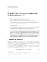
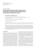
Figure 1: Left: A surface is projectively distorted in images I
1,2
, but the collineations w
1,2
from a planar patch tangent to this surface are not.
Right: Illustration of the discussed binocular camera system geometry.
that
(1) maximizing the image area that a unit of backprojec-
tion surface area corresponds to, and
(2) utilizing the same amount of image area across pairs
of image regions that are compared to
increases the accuracy of estimations of surface location and
orientation, which is the essential information for the recon-
struction of the imaged scene. The above proposals imply
spatial normalizations in the comparison of backprojected
image segments. Below, these normalizations are explained
and studied in a separate section each; first by being
theoretically formulated and then by being experimentally
compared with conventional approaches.
The remainder of this paper is organized as follows. In
Section 2, the stereo techniques that are related to the pro-
posed methods are reviewed and the notation utilized in this
paper is introduced. In Section 3, the first proposal is applied
to the family of space-sweeping algorithms. In Section 4,
the second proposal is applied to more generic cases of
volumetric stereo, which utilize the estimation of the surface
normal in the stereo reconstruction process. In Section 5, the
results are discussed and the proposed methods are placed in
the context of automatic reconstruction of visual scenes.
2. Related Work
The literature review of this section is focused at imple-
mentations of the texture uniqueness cue in stereo that
compare image regions after their backprojection to establish
correspondences, or else volumetric stereo approaches. A
comprehensive review of the broad literature on stereo
algorithms can be found in [5] and an evaluation of
contemporary stereo systems in [6].
The reasons for the wide applicability of the texture
uniqueness cue to the problem of stereo reconstruction
of scenes are multiple. It is independent from silhouette-
extraction which, also, requires an accurate segmentation
(e.g., [7]). It is also independent of any assumption requiring
that cameras occur around the scene (e.g., [8]) or on the
same baseline (e.g., [9, 10]). Moreover, it does not require
that cameras are spectrally calibrated, such as in voxel
carving/coloring approaches (e.g., [11–13]). In addition,
the locality of the cue due to the uniqueness constraint
facilitates multiview and parallel implementations, for real-
time applications [14–17].
Despite its locality, the uniqueness cue has been utilized
in semilocal [18] or more global formulations; for example,
via energy minimization [9, 19, 20]ordynamicprogram-
ming [21]. In these methods, a local similarity operator
is still utilized either as an oriented backprojection surface
segment (e.g., [18]) or as an image neighborhood (e.g.,
[9]), but interpreted differently by fusing its readings with
the well-established constraints on surface continuity. Thus,
regardless of how the readings of the similarity operator
are utilized by the reconstruction algorithm, the proposed
accuracy enhancement of the operator should only improve
the accuracy of the above approaches.
Methods that backproject and, then, compare the
acquired images can be classified based on if the (estimated)
orientation of the imaged surface is considered in the
backprojection process [18, 22–24], or not [25–30]. These
two classes are often, respectively, referred to as volumetric
and space-sweeping approaches. The notation and geometry
of this operation are first introduced.
Let I
1
and I
2
be the images of a calibrated image pair,
acquired from two cameras with centers
o
1,2
and principal
axes
e
1,2
; cyclopean eye is at
o = (
o
1
+
o
2
)/2andmeanoptical
axis is
e
= (
e
1
+
e
2
)/2. Let also a planar and square backprojec-
tion surface S,ofsizeα
×α,centeredat
p, with unit normal
n.
Backprojecting I
i
onto S yields image collineations w
i
(
p,
n):
w
i
p,
n
=
I
i
P
i
·
p + R(
n)
·
x
y
0
T
,(1)
where P
i
is the projection matrix of I
i
, R(
n)isarotation
matrix so that R(
n)
·[0 0 1]
T
=
n and x
, y
∈ [−α/2, α/2, ]
are local coordinates on S. When S is tangent at a world
surface, w
i
are identities of the surface pattern (see Figure 1
(left)). Thus I
1
(P
1
x)
= I
2
(P
2
x), for all
x
∈ S, and therefore
their similarity is optimal. Otherwise w
i
are dissimilar,
because they are collineations from different surface regions.
Scene reconstruction can be obtained by detecting the
positions at which the above similarity is high (greater than
threshold τ) and locally maximized along the direction of
the surface normal [23].
EURASIP Journal on Advances in Signal Processing 3
This volumetric similarity function s is computed at each
point in the reconstruction volume as
s
p
=
max
n
sim
w
1
p,
n
, w
2
p,
n
,(2)
κ
p
=
arg max
n
s
p
,(3)
where s(
p) is the optimal similarity value at
p,and
κ(
p)is
the optimizing orientation. To evaluate sim, an r
× r lattice
of points is assumed on S and the similarity metric sim is
usually one of the following: SAD, SSD, NCC, MNCC [31],
or photoconsistency [32]. (See [33]foracomparisonofthe
use of these metrics in stereo vision. Based on this work, the
MNCC metric is selected and, henceforth, utilized in this
paper.) The parameterization of
n requires two dimensions
which are expressed in terms of longitude and latitude.
Henceforth,alinefromacameraat
o to some point
p will
be referred to as a line of sight, from the camera to
p.
Volumetric approaches exhibit increased accuracy over
conventional epipolar-based stereo approaches, because the
comparison of image collineations is relieved of projective
distortion, and thus corresponding counterparts can be more
robustly detected in the acquired images. In multiview stereo,
there is no single notion of “depth,” and thus a world-
coordinate parameterized representation is required. In this
respect, volumetric approaches are very well suited for the
multicamera reconstruction of scenes. On the other hand,
they are computationally more complex due to the optimiza-
tion of orientation κ. To reduce the exhaustive search of the
above search space, the computation can be progressively
guided from coarse to fine scales [17], or constrained based
on the assumption that surfaces are continuous [9, 18, 20]. In
such approaches, α has been generally formulated as constant
[18, 22–24]. In [23, 24], α is modulated for the purpose
of a computational acceleration, through a hierarchical
multiresolution search. However, this modulation is identical
for any location and orientation of S and refers to the
granularity by which the reconstruction volume is sampled.
In other words, the proposed size-modulation (in Section 4)
is independent, and thus applicable to the above acceleration
approaches as an extension.
As shown in the next section, space or plane-sweeping
approaches are a special case of the above volumetric
formulation, in which only one potential orientation of
n
is considered. In these approaches, a planar backprojection
surface is translated (swept) along depth and the acquired
images are backprojected on, and then locally compared.
The orientation and shape of the sweeping surface is a
priori determined independently to the actual structure
of the imaged scene. Typically, orientation coincides with
the viewing direction, although multiple [34] orientations
have been considered. The backprojections of the acquired
images on this surface are locally compared as to their
visual similarity and the results are stored in a 2D similarity
map. A depth-ordered stack of such similarity maps is
generated and for each column along depth, the depth at
which similarity is maximized is considered to signify the
occurrence of the imaged surface. The backprojection and
local comparison of images are operations that quite fit in the
single-instruction multiple-data architecture, of commodity
graphics hardware. Thus a variety of GPU-accelerated space-
sweeping techniques can be found in the literature, for
example, [28, 29, 35].
Regarding the size of the backprojection surface in
space-sweeping approaches, it has been shown [26] that
projectively expanding this surface (as in [26–30
]) exploits
better the available pixel resolution, than implementing the
sweep as a simple translation of the sweeping plane [25, 32,
35–39]. This projective expansion is adopted by the approach
proposed in Section 3 and extended for the volumetric case
in Section 4.
3. Maximizing the Number of Sampled Pixels
for a Unit Backprojection Area
To indicate that the maximization of the number of sampled
pixels per unit of backprojection area is directly related with
the accuracy of reconstruction, the plane sweeping approach
is reviewed. The main reason to select this approach is due to
its practical applicability in obtaining successful stereo results
in binocular or combination of binocular approaches (e.g.,
[28, 34, 40, 41]).
The observation that is brought forward is illustrated
in (Figure 2, (left)). A planar backprojection surface is
increasingly slanted to an intersecting line of sight as this
line rotates from the center (coinciding then with the optical
axis) to the periphery of the image. Thus, a unit area of
this surface subtends more pixels when in the center of
the image than in its periphery. (In monocular vision,
rather than simulated backprojection, this effect is called
“foreshortening” and refers to the transformation of the
apparent size and shape of a surface when the viewpoint of
observation is varied.) It is thus clear that the number of
sampled pixels for a unit of backprojection-surface area is
maximized, when this unit surface is frontoparallel to the
line of sight from the camera to it.
The main difference of the proposed approach to planar
space sweeping is that the backprojection surface is modified
from planar to spherical. In addition, instead of performing
the search for local similarity maxima in the “depth”
direction, this search is performed along the direction of
sight; that is, along expanding spherical sectors, as opposed
to cubic voxels.
Using a spherical backprojection surface, a line of sight
t
departing from the cyclopean optical center is always perpen-
dicular to the backprojection surface for any eccentricity
within the field of view (FOV) (see Figure 2). The number of
sampled image pixels per unit area of backprojection surface
is maximal and independent of eccentricity. In contrast, a
planar frontoparallel backprojection surface is projected with
increasing slant relatively to
t as
moves to the periphery
of the image. To illustrate the above, a small area on
the backprojection surface is assumed as locally planar. As
shown in Figure 2, the subtended visual angle of this area is
maximized at the perpendicular posture CD. In any other
posture (e.g., AB for plane sweeping), this angle is smaller
since the image area subtended is decreased by a factor of
cos(CpA)inboth tilt and slant dimensions.
4 EURASIP Journal on Advances in Signal Processing
A
C
D
B
p
O
O
φ
2
φ
1
φ
0
Optical axis
•
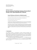
Figure 2: Flatland illustrations of the geometry of sphere sweeping. Left: A line of sight intersects a frontoparallel surface with increasing
slant, as it moves from the center of the image (φ
0
)toitsperiphery(φ
1
, φ
2
). Center: The subtended visual angle of a small area centered at
p
is maximized when this area is perpendicular to the line of sight from the projection center
o to
p and is less otherwise. Right: Illustrations
of the sector-(top) and voxel-(bottom) based volume tessellations. Visibility is naturally expressed in the first representation, whereas in the
second, traversing voxels obliquely is required for its computation.
3.1. Method Formulation. Let a series of concentric and
expanding spheres emanating from the cyclopean eye
o,with
corresponding radii d
i
. Let also the cyclopean view frustum
F from the cyclopean eye. The intersection of F with the
spheres produces the spherical parallelograms, or sectors, S
i
.
The angular openings (μ, λ) of the spherical segments are
matched to the horizontal and vertical FOVs of the cameras.
The concentric instances of the backprojection sector
at depth values d
δ
are noted as S
i
. The set of d
i
’s values
is called depth range D and i
∈{1, 2, ,n}.Values
d
i
are exponentially increasing, so that the images’ depth
granularity is fully exploited, while a minimum number of
depth values is evaluated [42]. Points on S
i
are parameterized
by an angular step of c and determined by spherical
coordinates ψ and ω. Parameterization variables ψ and ω are
determined as ψ
∈{c·i − μ; i = 0, 1, 2, ,2μ/c} and ω ∈
{
c· j − λ; j = 0,1, 2, ,2λ/c} and [μ/c] = μ/c,[λ/c] = λ/c.
Angle ψ varies on the xz and ω on the yz plane. For both ψ
and ω, value 0 corresponds to the orientation of the mean
optical axis
e. To generate sectors S
i
, a corresponding sector
S
0
is first defined on a unit sphere. A point
p = [xyz]
T
on S
0
is given by x = sin(ψ), y = cos(ψ)sin(ω), z =
cos(ψ)cos(ω). Its corresponding point
p
b
on S
i
is then
p
b
= d
i
R
z
(−ψ)R
y
(−ω)
p +
o
,(4)
where R
y
and R
z
are rotation matrices for rotations about
the yy
and zz
axes. The backprojection images are locally
compared with a w
× w correlation kernel K, which yields a
similarity score s. The strongest local maximum of s along a
line of sight indicates the estimated depth. The requirement
of locality for this maximum introduces robustness to
spurious maxima and textureless regions.
The remainder of the sweeping procedure is conven-
tional. For each S
i
, the stereo images (≥2) are sampled at the
projection S
i
’s points on the acquired images, thus forming
two (2μ/c
× 2λ/c) backprojection images, which are locally
compared. The similarity values are associated to the nodes
of a sector-interpretable grid (Figure 2,(right),butwhose
dataarestructuredinmemoryinaconventional3Dmatrix.
Notice that both sphere and plane sweeping can be
represented on a per voxel basis by the volumetric geometry
formulated in Section 2. Sphere sweeping is represented by
simply considering only the line of sight
t
=
p
−
o as the
value of
n in (2)and(3). To implement plane sweeping,
n is
always parallel to the optical axis, rather than the line of sight.
The shape of the surface is, then, implicitly defined by the
direction of
κ at which local maxima are detected within s.
Computational power is conserved in two ways. The first
way is by precomputing the pencil of vectors from
o to the
parameterized locations on S
0
at initialization and reusing
this result at the computation of S
i
at each depth. This pencil
corresponds to R
z
(−θ)R
y
(−φ)in(4), which is also the most
computationally demanding component of this equation due
to the matrix multiplication and trigonometric operations.
The second way is by reducing the number of evaluated
depth layers to the number of depths that can be sensed by
the given stereo system. For a binocular pair, this means to
parameterize d
i
in steps which correspond to a binocular
disparity of 1. In turn, this results in parameterizing d
i
exponentially as d
i
= d
0
+ β
i
, i = 1, 2, i
N
,whered
0
and i
N
define the sweeping interval and β is modulated so that the
farthest distance is imaged in the available image resolution
[42]. Memory is conserved similarly to [25], where a buffer
that stores only the similarity result for each depth is utilized.
Adifference of the proposed approach is that it buffers the
similarity result of both the previous and the next depths, in
order to determine if the maximum is truly local. Finally, a
second-order polynomial is fit around similarity maxima and
in the direction of search, to accurately increase the precision
of the reconstruction, in between depth intervals.
3.2. Experiments. The proposed approach was compared to
plane sweeping on the same binocular pairs and experi-
mental conditions. The scene imaged in each binocular pair
EURASIP Journal on Advances in Signal Processing 5
450
400
350
300
250
200
150
100
50
(Pixels)
100 200 300 400 500 600
(Pixels)
(a)
−800
−700
−600
−500
−400
−300
−200
(mm)
−200 0 200 400
(mm)
(b)
−800
−700
−600
−500
−400
−300
−200
(mm)
−300 −100 100 300
(mm)
(c)
450
400
350
300
250
200
150
100
50
(Pixels)
100 200 300 400 500 600
(Pixels)
(d)
260
280
300
320
340
360
(mm)
−360 −320 −280 −240
(mm)
(e)
240
260
280
300
320
340
220
(mm)
−350 −300 −250 −200
(mm)
(f)
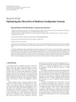
Figure 3: Comparison of planar and spherical backprojection surfaces in space sweeping. Each row shows an image from a binocular
pair and sections of the obtained reconstructions for planar (center) and spherical (right) backprojection surfaces. In the experiment, τ
=
·
7, FOV = π/4, π/4, tessellation of d
i
was 2 mm and regular. The stereoscopic image pair was obtained from a 156 mm-baseline camera pair.
The images were fully calibrated images and rectified for lens distortion.
was reconstructed independently by plane-sweeping and the
proposed sphere-sweeping methods.
To indicate differences among the results, a section
extracted from each reconstruction at the same coordinates
is presented. The sections were planar, vertical, and in the
direction of sight. In Figure 3,twosuchcomparisonsare
shown. In the top row, the section is close to the central image
column of the images of the stereo pair. In the bottom row,
the section corresponds to the periphery of the images. More
comparative experiments can be found in [26].
A small improvement effect between the two methods
can be observed in the reconstructions, when obtained
from the center of images (top row). As expected, the
improvement due to the spherical backprojection surface is
most intensely pronounced when comparing reconstructions
obtained from the periphery of images (bottom row). In
terms of reconstructed area, sphere sweeping provided about
≈15% more reconstructed points. A more quantitative con-
firmation of this result can be found in [26], where the eval-
uation of the reconstructions involved comparing the recon-
struction result to an independently acquired 3rd image.
3.3. Discussion. Through the presented experiments, the
expected accuracy improvement due to the utilization of
a spherical backprojection surface versus planar space-
sweeping has been demonstrated. In particular, this improve-
ment is most intensely pronounced in the reconstruction of
surfaces that occur in the periphery of the image, because in
this condition the backprojection plane is not perpendicular
to the line of sight, and thus undersampled. It is stressed
that, other than the change in the shape of the backprojection
surface, no other algorithmic modifications to planar space-
sweeping have been introduced in this technique. Therefore,
the execution of the proposed technique can be accelerated
in the GPU in the same way that planar space sweeping is
[28, 29, 35]. Also for much wider-baseline arrangements, it
has to be further studied whether the spherical surface should
be elongated to form a conic with three fixed points that pass
through the image centers [27], because then the line of sight
is not to the backprojection surface, and thus the periphery
is still undersampled.
For a binocular pair, parameterizing the reconstruction
volume into sectors instead of voxels provides a practical
surface parameterization for two reasons. First, because the
data required to compute visibility are already structured
with respect to visibility from the optical center. These data
refer to a sector-interpretable grid (see Figure 2, (right)),
but are structured in memory as a conventional 3D matrix.
Application, then, of visibility rules becomes more accurate,
because the oblique traversal of a regular voxel space,
which leads to discretization artifacts, is avoided. Second,
because the spatial granularity of surface discretization
in the reconstruction is a function of image resolution,
not world coordinates. Therefore, at greater distances, less
representational capacity is required to represent the imaged
surface, but still at the same detail.
6 EURASIP Journal on Advances in Signal Processing
350
300
250
200
150
100
50
(Pixels)
50 100 150 200 250 300 350 400
(Pixels)
60
40
20
(deg)
50 100 150 200 250 300 350
(deg)
60
40
20
(deg)
50 100 150 200 250 300 350
(deg)
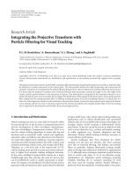
Figure 4: Accuracy evaluation of the patch operator using the first two frames of the “Venus” middlebury sequence. In the left figure, an
image of the binocular pair is shown with the target point of the experiment marked by a dot. The right figures show the similarity maps
obtained from the two experimental conditions: the top map shows the response of a constant-sized patch and the bottom map shows
the response with size-modulation. In these maps, diamonds mark the estimated normal and circles the ground truth. In the experiment,
α
= 250 length units, baseline was 100 length units, and r = 151. The projection of S subtended ≈ 50 pixels in the image.
4. Size-Modulation of Volumetric
Backprojection Surfaces
Volumetric approaches optimize the local orientation of the
backprojection surface on a per voxel basis, as in (2)and(3).
At a given point
p, the number of image pixels subtended
S is analogous to its obliqueness, or specifically, to the
reciprocals of distance squared and the cosines of relative tilt
and slant of S to the cameras. When α is constant, the greater
the obliqueness of S, the fewer the image pixels that the
(r
× r) image samples for w
1,2
are obtained from. Therefore,
there will always be a level of obliqueness above which the
same image intensity values will be sampled multiple times.
After this level, as obliqueness and/or distance continue to
increase, the population of these intensities will tend to
exhibit reduced variance. The reason is that the compared
intensity values are being sampled from decreasingly fewer
pixels, or otherwise, the same pixels are sampled multiple
times. As a result, variance is artificially reduced. Thus when
α is constant, a bias is predicted in the similarity function
in favor of greater slants and distances. The mathematical
reason of this bias is that variance occurs in the denominator
of the correlation function. The intuitive explanation is that
fewer image area supports now the similarity matching of
backprojections on S and, as a consequence, this matching
becomeslessrobusttolackofresolution.
In this section, a modulation of α that casts the apparent
(image) size of S invariant to distance and obliqueness is
proposed. Its effect is that pairs of compared collineations
correspond to the same image area, which is shown to
be important in the estimation of the imaged surface’s
normal.
4.1. Method Formulation. The size α of S is modulated so
that the image area at which S is projected remains invariant,
while S is hypothesized at different postures and distances
from the cameras. In particular, the side of S (or diameter,
for a circular S) is modulated as
α
=·
α
0
·d
d
0
·cos ω
; ω
= cos
−1
v
·
n
v
·
n
,(5)
where
v
=
p
−
o, d
=|
v
|, ω is the angle between
v and
n
and d
0
, α
0
initial parameters in units of world length. In the
above equation, (cos ω)
−1
normalizes for changes in posture,
d/d
0
for changes in distance and, as in Section 3, d
0
is a
constant which determines the closest considered distance
(or in an epipolar system, the largest considered disparity).
Finally, notice that even for a single location α is still a
variable of
n.
4.2. Experiments. Theproposedapproachwastestedin
both the angular and spatial domain, in two corresponding
experiments. In the first, the increment in the accuracy of
surface normal estimation at a single point is demonstrated.
In the second, the responses of the operator with and without
size modulation are compared, across the spatial extent of a
scene. A more detailed description of these experiments can
be found in [43].
In Figure 4, the improvement in estimating the sur-
face normal of a surface, induced by the proposed size-
modulation, is shown. In the figure, the responses obtained
from the same patch operator with and without size-
modulation are compared as to their accuracy. In the
experiment, a point on an imaged surface was selected and
the patch operator was centered and applied to this point.
The corresponding similarity values sim(w
1
(
p,
n), w
2
(
p,
n))
are shown in a longitude-latitude parameterization of
n,
with latitude corresponding to the horizontal axis. In the
maps,camerapose
c is at (0, 0), crosses mark the maximal
similarity value, and circles mark ground truth. The expected
improvement in accuracy induced by the proposed size-
modulation is confirmed in the experiment, by the greater
accuracy of the second condition. Notice that in the constant-
size condition, the global maximum occurred at the border
EURASIP Journal on Advances in Signal Processing 7
200
160
120
80
40
(Pixels)
50 150 250
(Pixels)
(a)
500
400
300
200
100
600
x-axis (voxels)
10
0
10
2
z-axis (voxels)
(b)
500
400
300
200
100
600
x-axis (voxels)
10
0
10
2
z-axis (voxels)
(c)
500
400
300
200
100
600
x-axis (voxels)
10
0
10
2
z-axis (voxels)
(d)
200
160
120
80
40
(Pixels)
50 150 250
(Pixels)
(e)
120
100
80
60
40
20
x-axis (voxels)
10
0
10
2
z-axis (voxels)
(f)
120
100
80
60
40
20
x-axis (voxels)
10
0
10
2
z-axis (voxels)
(g)
120
100
80
60
40
20
x-axis (voxels)
10
0
10
2
z-axis (voxels)
(h)
Figure 5: Shown is “Map” middlebury stereo pair (left column) and three separate calculations of s across a vertical section, through the
middle of the foreground surface. The bottom figures are zoom-in details on the part that corresponds to the foreground surface in the
image pair. The z-axes (horizontal in maps) are logarithmic. In the bottom figures, ground truth is marked with a dashed line. Columns 2
and3(fromtheleft)correspondtothesmallandlargeα, respectively. The right column shows the response of for the size-modulated α.
of this map, at a posture more oblique than ground truth.
This type of spuriously high-similarity values is expected,
because at very oblique poses relative to the optical axis, the
patch projects to just a few pixels.
The second experiment shows the increment in the
accuracy of the volumetric similarity function s across the
spatial extent of a scene. This similarity function, s,was
evaluated for all the points of a reconstruction volume in
three conditions; a small, a large, and a size-modulated α
(see Figure 5). In the 2nd column, a fine α was used, hence
the noisy response at the background. Using a larger α (3rd
column) yields a smoother response in greater distances,
but diminishes any detail that could be observed in short
range. In the 4th column, α is projectively increased, thus
normalizing the precision of reconstruction by the area that
a pixel images at that distance. In the bottom figures, ground
truth is marked with a dashed line.
The same effect is more intensely pronounced when the
scene exhibits a greater range of depth. In the experiment
of Figure 6, the performance of a constant α is compared
against a size-modulated α for a scene that features
≈ 15 m
of depth. In the experiment, the size modulation of α yields
a less noisy correlation response, particularly at greater
distances than a constant α.
4.3. Discussion. In this section, it is argued that modulating
the size of a backprojection planar patch operator so that
the patch projects at an equal amount of image area for
each location and orientation produces more accurate results
than when retained constant. The increase in robustness
of the proposed approach versus approaches that utilize a
patch of constant size was confirmed through reconstruction
experiments, where ground truth was known.
Besides the importance of the accuracy of surface
localization, the accuracy of surface normal estimation is
important in reconstruction algorithms, because it facilitates
accuracy in the final reconstruction as well [17]. Volumetric
stereo algorithms utilize the readings of the planar patch
operator S in different ways. For example, in [18] similarity
values are provided to a global optimization, the result
of which is an isosurface that represents the reconstructed
surface. In [22] besides texture similarity, photometrical
properties are also computed on the patch and a multidimen-
sional optimization is employed to determine the occupied
voxels. In [23, 24], spatially local maxima in the response of
the operator are regarded as a cue to surface occurrence. It is,
thus, argued that the proposed modulation can be directly
adopted by volumetric methods, such as the above, that
utilize a constant-size hypothetical patch.
5. Conclusion
In this paper, the resolution effects of image backprojection
for the implementation of the texture uniqueness cue have
been studied, and methods to utilize image resolution more
efficiently, in this process, have been proposed. The proposed
techniques target the accuracy of results that are required in
3D TV applications, based on size and shape modulations of
the backprojected surfaces. The volumetric representation of
the output and the estimations of surface normals facilitate
surface interpolation techniques that boost precision and
rendering quality [23]. The common notation and locality
of the proposed approaches have facilitated their sequential
integration into a highly parallelizable computational mod-
ule, which is utilized as a software engine for the production
of 3D video for free-viewpoint rendering [17].
8 EURASIP Journal on Advances in Signal Processing
600
500
400
300
200
100
100 200 300 400 500 600 700 800
(a)
600
500
400
300
200
100
100 200 300 400 500 600 700 800
(b)
800
700
600
500
400
300
200
100
200 400 600 800 1000 1200
(c)
800
700
600
500
400
300
200
100
200 400 600 800 1000 1200
(d)
Figure 6: Shown on the top row is a stereo pair and on the bottom row two separate calculations of s across a vertical section, along the xx
axis of the scene. The section is indicated on the top row images by projecting the reconstructed points along this section back to the original
images. In the bottom row, the left image corresponds to a constant α and the right to a size-modulated α.
The ability to commonly formulate the methods of Sec-
tions 3 and 4 facilitates the integration of the two proposed
approaches in a coarse to fine estimation of regions of interest
within
V. In this system [17],
V is initially approximated by a
sweeping technique at coarse scale. The local maxima at that
scale are utilized to determine volumetric (3D) regions of
interestatwhich
V is to be recomputed at higher resolution
and angular precision, using the optimization of (2)and
(3). To seamlessly achieve this integration, the spherical
sweeping approach is formulated on a per voxel basis as
shown in Section 2. The per voxel estimations of
V from the
sweeping process are then utilized as initial estimations that
constrain the angular and spatial search spaces.
The volumetric locality of
V’s computation permits the
volumetric partitioning of data for the parallelization of the
process. In fact, the computation of
V is parallelizable not
only on a per voxel, but also on a per evaluated orientation
basis (i.e., for every
n in (2)). However, because surfaces
occur only in the minority of voxels of a reconstruction
volume, efficiently balancing the computational load across a
number of computational resources is a topic of future study.
The challenge is to dynamically focus on computational
resources at the regions of interest, while also distributing
appropriately the amounts of computation to minimize
response time. In this domain, the most efficient distribu-
tion of computation among CPU and GPU computational
resources is also a topic that remains to be studied.
The utilization of a volumetric representation, such as
V, and the estimation of surface normals are crucial to the
fusion of multiple views [23]. When fusing input from mul-
tiple views, errors in camera registration due to calibration
noise produce inaccuracies and duplicate occurrences of the
same surface [15]. To cope with the task of merging multiple
views, similarity scores are fused in a common voxel grid
[23]. More recently, other such fusion approaches have been
formulated, for example, [41, 44]. The present work is of
service to the above approaches in enhancing the veridity of
the readings of the fused volumetric similarity operators.
Another future direction of this work is in the integration
of the computational findings regarding the accuracy of
the volumetric patch operator with works that utilize such
operators as discussed in Section 4.3. Most importantly, the
ability of volumetric approaches to represent the interme-
diate results in a local basis facilitates the integration with
other cues to shape those can be essential to the goals of
scene reconstruction. For example, shape-from-silhouette
is a method that can constrain significantly the search
space while shape-from-shading and space carving can be
the two of the few choices for surface reconstruction at
textureless image areas. Moreover, constraints that arise from
the detection of characteristic structures, such as planes [45,
EURASIP Journal on Advances in Signal Processing 9
46], and even from monocular perspective cues [47, 48]can
significantly constrain the search space and prune outliers.
Acknowledgment
The authors are grateful for support through the 3D TV
European NoE, 6th Framework IST Programme.
References
[1] M. Levoy and P. Hanrahan, “Light field rendering,” in Pro-
ceedings of the 23rd Annual Conference on Computer Graphics
and Interactive Techniques (SIGGRAPH ’96), pp. 31–42, New
Orleans, La, USA, August 1996.
[2] D. Marr and T. Poggio, “Cooperative computation of stereo
disparity,” Science, vol. 194, no. 4262, pp. 283–287, 1976.
[3] D. Marr and T. Poggio, “A computational theory of human
stereo vision,” Proceedings of the Royal Society of London B, vol.
204, no. 1156, pp. 301–328, 1979.
[4] A. S. Ogale and Y. Aloimonos, “Stereo correspondence with
slanted surfaces: critical implications of horizontal slant,”
in Proceedings of the IEEE Conference on Computer Vision
and Pattern Recognition (CVPR ’04), vol. 1, pp. 568–573,
Washington, DC, USA, June-July 2004.
[5]M.Z.Brown,D.Burschka,andG.D.Hager,“Advancesin
computational stereo,” IEEE Transactions on Pattern Analysis
and Machine Intelligence, vol. 25, no. 8, pp. 993–1008, 2003.
[6] D. Scharstein and R. Szeliski, “A taxonomy and evaluation of
dense two-frame stereo correspondence algorithms,” Interna-
tional Journal of Computer Vision, vol. 47, no. 1–3, pp. 7–42,
2002.
[7] A. Laurentini, “The visual hull concept for silhouette-based
image understanding,” IEEE Transactions on Pattern Analysis
and Machine Intelligence, vol. 16, no. 2, pp. 150–162, 1994.
[8] G.K.M.Cheung,T.Kanade,J Y.Bouguet,andM.Holler,“A
real time system for robust 3D voxel reconstruction of human
motions,” in Proceedings of the IEEE Conference on Computer
Vision and Pattern Recognition (CVPR ’00), vol. 2, pp. 714–720,
Hilton Head Island, SC, USA, June 2000.
[9] V. Kolmogorov and R. Zabih, “Multi-camera scene recon-
struction via graph cuts,” in Proceedings of the 7th European
Conference on Computer Vision (ECCV ’02), pp. 82–96,
Copenhagen, Denmark, May 2002.
[10] M. Okutomi and T. Kanade, “A multiple-baseline stereo,” IEEE
Transactions on Pattern Analysis and Machine Intelligence, vol.
15, no. 4, pp. 353–363, 1993.
[11] K. N. Kutulakos and S. M. Seitz, “A theory of shape by space
carving,” International Journal of Computer Vision, vol. 38, no.
3, pp. 199–218, 2000.
[12]W.Culbertson,T.Malzbender,andG.G.Slabaugh,“Gen-
eralized voxel coloring,” in Proceedings of the International
Workshop on Vision Algorithms: Theory and Practice, pp. 100–
115, Corfu, Greece, September 1999.
[13] G. G. Slabaugh, W. B. Culbertson, T. Malzbender, M. R.
Stevens, and R. W. Schafer, “Methods for volumetric recon-
struction of visual scenes,” International Journal of Computer
Vision, vol. 57, no. 3, pp. 179–199, 2004.
[14] J. Lanier, “Virtually there,” Scientific American, vol. 284, no. 4,
pp. 66–75, 2001.
[15] J. Mulligan, X. Zabulis, N. Kelshikar, and K. Daniilidis,
“Stereo-based environment scanning for immersive telepres-
ence,” IEEE Transactions on Circuits and Systems for Video
Technology, vol. 14, no. 3, pp. 304–320, 2004.
[16] N. Kelshikar, X. Zabulis, J. Mulligan, et al., “Real-time terascale
implementation of tele-immersion,” in Proceedings of the
International Conference on Computational Science (ICCS ’03),
pp. 33–42, Melbourne, Australia, June 2003.
[17] X. Zabulis and G. Kordelas, “Efficient, precise, and accurate
utilization of the uniqueness constraint in multi-view stereo,”
in Proceedings of the 3rd IEEE International Symposium on 3D
Data Processing, Visualization and Transmission (3DPVT ’06),
pp. 137–144, Chapel Hill, NC, USA, June 2006.
[18] O. Faugeras and R. Keriven, “Complete dense stereovision
using level set methods,” in Proceedings of the 5th European
Conference on Computer Vision (ECCV ’98), vol. 1, pp. 379–
393, Freiburg, Germany, June 1998.
[19] S. Paris, F. X. Sillion, and L. Quan, “A surface reconstruction
method using global graph cut optimization,” International
Journal of Computer Vision, vol. 66, no. 2, pp. 141–161, 2006.
[20] J. Kim, V. Kolmogorov, and R. Zabih, “Visual correspon-
dence using energy minimization and mutual information,”
in Proceedings of the 9th IEEE International Conference on
Computer Vision (ICCV ’03), vol. 2, pp. 1033–1040, Nice,
France, October 2003.
[21] I. J. Cox, S. L. Hingorani, S. B. Rao, and B. M. Maggs, “A
maximum likelihood stereo algorithm,” Computer Vision and
Image Understanding, vol. 63, no. 3, pp. 542–567, 1996.
[22] R. L. Carceroni and K. N. Kutulakos, “Multi-view scene
capture by surfel sampling: from video streams to non-rigid
3D motion, shape and reflectance,” International Journal of
Computer Vision, vol. 49, no. 2-3, pp. 175–214, 2002.
[23] X. Zabulis and K. Daniilidis, “Multi-camera reconstruction
based on surface normal estimation and best viewpoint selec-
tion,” in Proceedings of the 2nd International Symposium on 3D
Data Processing, Visualization, and Transmission (3DPVT ’04),
pp. 733–740, Thessaloniki, Greece, September 2004.
[24] A. Bowen, A. Mullins, R. Wilson, and N. Rajpoot, “Light
field reconstruction using a planar patch model,” in Proceed-
ings of the 14th Scandinavian Conference on Image Analysis
(SCIA ’05), pp. 85–94, Joensuu, Finland, June 2005.
[25] R. T. Collins, “A space-sweep approach to true multi-image
matching,” in Proceedings of the IEEE Conference on Computer
Vision and Pattern Recognition (CVPR ’96), pp. 358–363, San
Francisco, Calif, USA, June 1996.
[26] X. Zabulis, G. Kordelas, K. Mueller, and A. Smolic, “Increas-
ing the accuracy of the space-sweeping approach to stereo
reconstruction, using spherical backprojection surfaces,” in
Proceedings of the International Conference on Image Processing
(ICIP ’06), pp. 2965–2968, Atlanta, Ga, USA, October 2006.
[27] M. Pollefeys and S. Sinha, “Iso-disparity surfaces for general
stereo configurations,” in Proceedings of the 8th European
Conference on Computer Vision (ECCV ’04), pp. 509–520,
Prague, Czech Republic, May 2004.
[28] R. Yang, G. Welch, and G. Bishop, “Real-time consensus-based
scene reconstruction using commodity graphics hardware,” in
Proceedings of the 10th Pacific Conference on Computer Graphics
and Applications (PCCGA ’02), pp. 225–234, Beijing, China,
October 2002.
[29] M. Li, M. Magnor, and H P. Seidel, “Hardware-accelerated
rendering of photo hulls,” Computer Graphics Forum, vol. 23,
no. 3, pp. 635–642, 2004.
[30] V. Nozick, S. Michelin, and D. Arqus, “Image-based rendering
using plane-sweeping modelisation,” in Proceedings of the
International Association for Pattern Recognition—Machine
Vision Applications (IAPR ’05), pp. 468–471, Tsukuba, Japan,
May 2005.
10 EURASIP Journal on Advances in Signal Processing
[31] H. Moravec, Robot Rover Visual Navigation, Computer Sci-
ence: Artificial Intelligence, UMI Research Press, Ann Arbor,
Mich, USA, 1981.
[32] K. N. Kutulakos and S. M. Seitz, “A theory of shape by space
carving,” International Journal of Computer Vision, vol. 38, no.
3, pp. 199–218, 2000.
[33] J. Mulligan, V. Isler, and K. Daniilidis, “Trinocular stereo: a
real-time algorithm and its evaluation,” International Journal
of Computer Vision, vol. 47, no. 1–3, pp. 51–61, 2002.
[34] D. Gallup, J M. Frahm, P. Mordohai, Y. Qingxiong, and
M. Pollefeys, “Real-time plane-sweeping stereo with multiple
sweeping directions,” in Proceedings of the IEEE Conference on
Computer Vision and Pattern Recognition (CVPR ’07), pp. 1–8,
Minneapolis, Minn, USA, June 2007.
[35] C. Zach, A. Klaus, B. Reitinger, and K. Karner, “Optimized
stereo reconstruction using 3d graphics hardware,” in Proceed-
ings of the Workshop of Vision, Modelling, and Visualization
(VMV ’03), pp. 119–126, Munich, Germany, November 2003.
[36] J. Bauer, K. Karner, and K. Schindler, “Plane parameter
estimation by edge set matching,” in Proceedings of the 26th
Workshop of the Austrian Associat i on for Pattern Recognition,
pp. 29–36, Graz, Austria, September 2002.
[37]C.Zach,A.Klaus,J.Bauer,K.Karner,andM.Grabner,
“Modeling and visualizing the cultural heritage data set of
Graz,” in Proceedings of the Conference on Virtual Reality,
Archeology, and Cultural Heritage, pp. 219–226, Glyfada,
Greece, November 2001.
[38] C. Zhang and T. Chen, “A self-reconfigurable camera array,”
in Proceedings of the International Conference on Computer
Graphics and Interactive Techniques (SIGGRAPH ’04), p. 151,
Los Angeles, Calif, USA, August 2004.
[39] T. Werner, F. Schaffalitzky, and A. Zisserman, “Automated
architecture reconstruction from close-range photogramme-
try,” in Proceedings of the CIPA International Symposium,
Potsdam, Germany, September 2001.
[40] I. Geys, T. P. Koninckx, and L. Van Gool, “Fast interpolated
cameras by combining a GPU based plane sweep with a
Max-flow regularisation algorithm,” in Proceedings of the 2nd
International Symposium on 3D Data Processing, Visualization,
and Transmission (3DPVT ’04), pp. 534–541, Thessaloniki,
Greece, September 2004.
[41] M. Goesele, B. Curless, and S. M. Seitz, “Multi-view stereo
revisited,” in Proceedings of the IEEE Conference on Computer
Vision and Pattern Recognition (CVPR ’06), vol. 2, pp. 2402–
2409, New York, NY, USA, June 2006.
[42] J X. Chai, X. Tong, S C. Chan, and H Y. Shum, “Plenop-
tic sampling,” in Proceedings of the 27th Annual Confer-
ence on Computer Graphics and Interactive Techniques (SIG-
GRAPH ’00), pp. 307–318, New Orleans, La, USA, July 2000.
[43] X. Zabulis and G. D. Floros, “Modulating the size of back-
projection surface patches, in volumetric stereo, for increasing
reconstruction accuracy and robustness,” in Proceedings of the
True Vision Capture, Transmission and Display of 3D Video
Conference (3DTV ’07), pp. 1–4, Kos Island, Greece, May 2007.
[44] M. Habbecke and L. Kobbelt, “A surface-growing approach
to multi-view stereo reconstruction,” in Proceedings of the
IEEE Conference on Computer Vision and Pattern Recognition
(CVPR ’07), pp. 1–8, Minneapolis, Minn, USA, June 2007.
[45] M. I. A. Lourakis, A. A. Argyros, and S. C. Orphanoudakis,
“Detecting planes in an uncalibrated image pair,” in Proceed-
ings of the British Machine Vision Conference (BMVC ’02), vol.
2, pp. 587–596, Cardiff, UK, September 2002.
[46] M. Pollefeys, F. Verbiest, and L. Van Gool, “Surviving domi-
nant planes in uncalibrated structure and motion recovery,” in
Proceedings of the 7th European Conference on Computer Vision
(ECCV ’02), pp. 837–851, Copenhagen, Denmark, May 2002.
[47] A. Saxena, S. Chung, and A. Y. Ng, “Learning depth
from single monocular images,” in
Proceedings of the 20th
Annual Conference on Neural Information Processing Systems
(NIPS ’06), vol. 18, Vancouver, Canada, December 2006.
[48] L. Bergen and F. Meyer, “A novel approach to depth order-
ing in monocular image sequences,” in Proceedings of the
IEEE Conference on Computer Vision and Pattern Recognition
(CVPR ’00), vol. 2, pp. 536–541, Hilton Head Island, SC, USA,
June 2000.