Báo cáo hóa học: " Research Article Capacity of Time-Hopping PPM and PAM UWB Multiple Access Communications over Indoor Fading Channels" ppt
Bạn đang xem bản rút gọn của tài liệu. Xem và tải ngay bản đầy đủ của tài liệu tại đây (855.99 KB, 9 trang )
Hindawi Publishing Corporation
EURASIP Journal on Wireless Communications and Networking
Volume 2008, Article ID 273018, 9 pages
doi:10.1155/2008/273018
Research Article
Capacity of Time-Hopping PPM and PAM UWB Multiple Access
Communications over Indoor Fading Channels
Hao Zhang
1
and T. Aaron Gulliver
2
1
Department of Electrical Engineering, Ocean University of China, 5 Yushan Road, Qingdao 266003, China
2
Department of Electrical & Computer Engineering, University of Victoria, P.O. Box 3055, STN CSC, Victoria, BC, Canada V8S 4W9
Correspondence should be addressed to Hao Zhang,
Received 27 June 2007; Revised 10 October 2007; Accepted 10 February 2008
Recommended by Weidong Xiang
The capacity of time-hopping pulse position modulation (PPM) and pulse amplitude modulation (PAM) for an ultra-wideband
(UWB) communication system is investigated based on the multipath fading statistics of UWB indoor wireless channels. A
frequency-selective fading channel is considered for both single-user and multiple-user UWB wireless systems. A Gaussian
approximation based on the single-user results is used to derive the multiple access capacity. Capacity expressions are derived
from a signal-to-noise-ratio (SNR) perspective for various fading environments. The capacity expressions are verified via Monte
Carlo simulation.
Copyright © 2008 H. Zhang and T. A. Gulliver. This is an open access article distributed under the Creative Commons Attribution
License, which permits unrestricted use, distribution, and reproduction in any medium, provided the original work is properly
cited.
1. INTRODUCTION
Ultra-wideband (UWB) [1] communication systems employ
ultrashort impulses to transmit information which spreads
the signal energy over a very wide frequency spectrum of
several GHz. Multipath fading is one of the major challenges
faced by UWB systems. The statistics of narrowband indoor
wireless channels have been extensively investigated and
several widely accepted channel models have been developed.
However, narrowband models are inadequate for the char-
acterization of UWB channels because of their extremely
large transmission bandwidth and nanosecond path delay
difference resolvable paths. Considering these characteristics,
the so-called POCA-NAZU model and the stochastic tapped-
delay-line (STDL) propagation model have been proposed
for UWB indoor wireless channels [2, 3]. The parameters of
the STDL model were obtained from channel measurements.
It was shown that the Nakagami distribution is a better fit
for the indoor wireless magnitude statistics rather than the
distributions typically used in narrowband systems. Recently,
the IEEE 802.15.4a group presented a comprehensive study
of the UWB channel over the frequency range 2–10 GHz
for indoor residential, indoor office, industrial, outdoor,
and open outdoor environments [4]. It was suggested
that small-scale fading be added based on the well-known
Saleh-Valenzuela model. A list of parameters for different
environments was also presented in [4]. Although the
channel model presented in [4] describes the UWB indoor
channel in more detail than the STDL model, it is difficult
to use for capacity and performance analysis because of
its complexity. In addition, it is not suitable for deriving
general results which can be very useful to system designers.
Therefore to facilitate and simplify the analysis, we employ
the STDL model in this paper to study the capacity of
a UWB system with PPM and PAM over indoor fading
channels.
Extensive research has been conducted on the capacity
of UWB systems in both AWGN and fading channels. In
[5, 6], the channel capacity of UWB systems with M-
ary pulse position modulation (PPM) is examined, and
this is extended to biorthogonal PPM (BPPM) and pulse
position amplitude modulation (PPAM) in [7, 8]. PPM and
PAM with receive diversity are considered in [9]. However,
these results are based on the assumption of an additive
white Gaussian noise (AWGN) channel without considering
multipath fading. In the following sections, we extend the
analysis in [7–9] to derive the capacity of a UWB PPM and
PAM system over indoor fading channels for both single
and multiple user environments from a signal-to-noise ratio
(SNR) perspective.
2 EURASIP Journal on Wireless Communications and Networking
The rest of the paper is organized as follows. In Section 2,
the time-hopping PPM and PAM UWB systems are intro-
duced and a statistical model for the UWB indoor multipath
channel is described. Section 3 presents the capacity analysis
of PPM and PAM UWB systems over indoor fading channels
with a single user. The discussion also covers frequency flat
fading channels. The relationship between reliable commu-
nication distance and channel capacity subject to FCC Part
15 rules is given. The multiple access capacity of PPM and
PAM UWB systems is analyzed in Section 4 via a Gaussian
approximation. Numerical results are presented in Section 5
for the capacity over indoor fading channels. Finally, some
conclusions are given in Section 6.
2. SIGNAL CONSTRUCTION AND STATISTICAL MODEL
FOR MULTIPATH FADING UWB INDOOR CHANNELS
2.1. Signal construction and system model
A typical time-hopping format for the output of the kth user
in a UWB system is given by [7]
s
(k)
(t) =
∞
j=−∞
A
(k)
d
j/N
s
q
t − jT
f
−c
(k)
j
T
c
− δ
d
(k)
j/N
s
,(1)
where A
(k)
is the signal amplitude, q(t) represents the
transmitted impulse waveform that nominally begins at time
zero at the transmitter, and the quantities associated with (k)
are transmitter dependent. T
f
is the frame time, which is
typically a hundred to a thousand times the impulse width
resulting in a signal with a very low duty cycle. Each frame
is divided into N
h
time slots with duration T
c
. The pulse
shift pattern c
(k)
j
,0 ≤ c
(k)
j
<N
h
(also called the time-
hopping sequence), is pseudorandom with period T
c
. This
provides an additional shift in order to avoid catastrophic
collisions due to multiple access interference. The sequence
d is the data stream generated by the kth source after channel
coding, and δ is the additional time shift utilized by the N-
ary pulse position modulation. If N
s
> 1, a repetition code is
introduced, that is, N
s
pulses are used for the transmission of
the same information symbol.
For M-ary PPM, we have constant unit signal amplitude,
that is, A
(k)
d
j/N
s
= 1, so (1)canbewrittenas
s
(k)
(t) =
∞
j=−∞
q
t − jT
f
−c
(k)
j
T
c
− δ
d
(k)
j/N
s
. (2)
For M-ary PAM, we have no additional modulation time
shift, that is, δ
d
(k)
j/N
s
= 0. The normalized amplitude is defined
as A
m
= (2m −1 −M)
E
g
, E
g
= 3E
av
/(M
2
−1), 1 ≤ m ≤ M,
where E
av
is the average energy of the signal. Equation (1)
can then be written as
s
(k)
(t) =
∞
j=−∞
A
d
(k)
j/N
s
q
t − jT
f
−c
(k)
j
T
c
. (3)
The received signal over an additive white Gaussian noise
(AWGN) channel can be modeled as the derivative of the
transmitted pulses assuming propagation in free space [9].
Thus the received signal over indoor fading channels can be
modeled as
r(t)
=
L
l=1
K
k=1
h
lk
(t)
s
(k)
(t)
+ w(t)
=
L
l=1
K
k=1
h
lk
(t)
∞
j=−∞
A
(k)
d
j/N
s
p
t−jT
f
−c
(k)
j
T
c
− δ
d
(k)
j/N
s
+w(t),
(4)
where w(t) is AWGN with double-sided power spectral
density N
o
, K is the number of simultaneous active users,
p(t) is the received pulse waveform, L is the receive diversity
order, that is, the number of resolvable paths in the case of
a single-input single-output (SISO) system, and h(t) is the
time-varying attenuation. For an AWGN channel, if only one
user is present, the optimal receiver for PPM is a bank of M
correlation receivers followed by a detector. When more than
one link is active in the multiple-access system, the optimal
PPM receiver has a complex structure that takes advantage
of all receiver knowledge regarding the characteristics of
the multiple-access interference (MAI) [10]. However, for
simplicity, an M-ary correlation receiver is typically used
even when there is more than one active user. For PAM,
only one correlation receiver is required for both the single
user and multiuser cases. The receivers used for an AWGN
channel can also be applied to multipath fading channels
subject to the channel state information being fully available
to the receiver for equalization.
2.2. Statistical model for the UMB indoor wireless
multipath fading channel
Due to the ultrashort pulses, UWB indoor signals experience
frequency-selective fading during transmission. The propa-
gation model of the indoor wireless channel can be described
by the impulse response of the channel as [3]
h(t)
=
L
l=1
a
l
(t)δ
t −τ
l
(t)
,(5)
where t is the observation time, L is the number of the
resolvable paths, τ
l
(t) is the arrival-time of the received
signal via the lth path which is log-normal distributed [5],
a
l
(t) is the random time-varying amplitude attenuation,
and δ denotes the Dirac delta function. Without loss of
generality, we define τ
l
(t) so that τ
1
<τ
2
< ··· <τ
L
.For
narrowband systems, the number of scatterers within one
resolvable path is large, so that the central limit theorem
can be applied, leading to a Gaussian model for the channel
impulse response. However, UWB systems can resolve paths
with a nanosecond path delay difference, hence the number
of scatterers within one resolvable path is only on the order of
2or3[3]. Since the number of scatterers is too small to apply
the central limit theorem, the distribution of a
l
(t) cannot
be modeled as Gaussian. Although the exact distribution of
H. Zhang and T. A. Gulliver 3
a
l
(t)isdifficult to derive, several models have been proposed
[2, 3] considering that a small number of scatterers best
describes the indoor wireless channel. In [2], the so-called
POCA-NAZU model is introduced to describe the small
scale multipath fading amplitudes for UWB signals, while [3]
derives a STDL propagation model from experimental data.
It is shown in [3] that the Nakagami distribution is the best
fit for the indoor small-scale magnitude statistics.
We first write a
l
(t)as
a
l
(t) = v
l
a
l
,(6)
where v
l
= sign(a
l
)anda
l
=|a
l
(t)|. The PDF of the
amplitude of a
l
is given by [3]
p
a
l
=
2
Γ(m)
m
Ω
l
m
a
2m−1
l
e
−ma
2
l
/Ω
l
,(7)
where Γ() denotes the Gamma function, Ω
l
= E[a
2
l
], and
m = [E[a
2
l
]]
2
/Var [ a
2
l
], which is a function of l and m ≥ 1/2.
Note that a
l
≥ 0. As τ
1
<τ
2
< ··· <τ
L
, it is reasonable
to assume that the power of a
l
is exponentially decreasing
with increasing delay. To make the channel characteristics
analyzable without affecting the generality of the channel, we
further define v
l
as a random variable that takes the values
+1 or
−1 with equal probability, and τ
l
as a deterministic
constant within the resolvable path time interval defined by
τ
l
= (l − 1)τ [11], where τ = 1/W and W is the signal
bandwidth.
3. CAPACITY ANALYSIS WITH A SINGLE USER
3.1. Equivalent SNR
With a single user active in the system, (4) can be simplified
to
r(t)
=
L
l=1
a
l
(t)δ
t −τ
l
(t)
X(t)+w(t), (8)
where X(t)
= (s(t))
=
∞
j=−∞
A
d
j/N
s
p(t − jT
f
− c
j
T
c
−
δ
d
j/N
s
). The equivalent SNR of (8)isgivenby
γ
=
w/2
w/2
G
X
( f )
H( f )
2
df
N
0
W
,(9)
where G
X
( f ) is the power spectral density (PSD) of the
UWB signal determined by the pulse shape and modulation
scheme, and H( f ) is the PSD of h(t)givenbyH( f )
=
L
l
=1
v
l
a
l
e
−j2πf(l−1)τ
.Thuswehave
H( f )
2
=
⎛
⎝
L
l=1
v
l
a
l
cos
2πf(l−1)τ
⎞
⎠
2
+
⎛
⎝
L
l=1
v
l
a
l
sin
2πf(l−1)τ
⎞
⎠
2
.
(10)
The equivalent SNR γ can be written as
γ
=
w/2
w/2
G
X
( f )[α + β]df
N
0
W
, (11)
where α denotes
(
L
l=1
v
l
a
l
cos
(2πf(l
−1)τ))
2
and β denotes
(
L
l
=1
v
l
a
l
sin(2πf(l −1)τ))
2
.
Without loss of generality, we assume X(t)hasa
uniformly distributed PSD to simplify the analysis, that is,
G
X
( f ) =
⎧
⎪
⎨
⎪
⎩
P
x
W
where f
∈
−
W
2
W
2
,
0 otherwise,
(12)
where P
x
is the power of the received UWB signal. Equation
(11) can then be written as
γ
= γ
s
1
π
π
0
L
l=1
v
l
a
l
cos
(l − 1)u
2
+
L
l=1
v
l
a
l
sin
(l − 1)u
2
du,
(13)
where γ
s
= P
X
/WN
0
is the symbol SNR of the UWB system.
This shows that the equivalent SNR γ can be denoted by the
symbol SNR modified according to the number of paths and
the fading coefficients.
3.2. Capacity for frequency-selective fading channels
In general, the channel capacity is a function of the channel
realization, transmitted signal power, and noise. As UWB
communication is via ultrashort pulses, it is reasonable
to assume that the channel is essentially fixed during one
pulse duration. With this quasistatic assumption, the instan-
taneous capacity over frequency-selective fading channels
can be calculated using the equivalent SNR in (13). The
normalized capacity with respect to the bandwidth can then
be obtained by averaging the instantaneous capacity over
the PDF of the random time-varying amplitude attenuation
vector a:
C =
∞
0
log
2
(1 + γ)p(a)da
=
∞
0
···
∞
0
log
2
1+γ
s
1
π
π
0
L
l=1
v
l
a
l
cos
(l − 1)u
2
+
L
l=1
v
l
a
l
sin
(l − 1)u
2
du
×
L
l=1
p
a
l
da
1
da
2
···da
L
.
(14)
For frequency-selective fading, L>1and(14)willbe
evaluated via Monte Carlo simulation since it is difficult
to derive a simple closed form expression. Although (14)
4 EURASIP Journal on Wireless Communications and Networking
is calculated based on a specific pulse shape, the standard
capacity expression has continuous inputs and continuous
outputs. Therefore considering this restriction, (14)doesnot
represent the exact channel capacity, but it does provide
guidance and a means of comparison from the capacity
perspective.
Note that frequency flat fading is also covered by (14)
using L
= 1, and this can be expressed in closed form after
some simple manipulations as shown in Appendix A:
C =
1
Γ(m)
∞
0
log
2
1+
u
ρ
u
m−1
e
−u
du
=
ρ
m
Γ(m)
(log
2
e) f
1
ρ
, m
−1
,
(15)
where ρ
= m/Ωγ
s
,and
f (
γ
c
, n) =
∞
0
ln(1 + γ
s
)γ
n
s
e
−γ
s
/γ
c
dγ
s
= (−1)
n−1
γ
c
e
1/γ
c
Ei
−
1
γ
c
+
n
k=1
n!
(n −k)!
×
k
j=0
k
−j−1
i=0
(−1)
n−k
(k − j −1 −i)!
1
(k − j)
γ
i+j+2
c
+(−1)
n−k−1
γ
k+1
c
e
1/γ
c
Ei
−
1
γ
c
(16)
as described in [12].
3.3. Channel capacity for UWB PPM and PAM over
frequency-selective fading channels
A channel with PPM or PAM modulation has discrete-valued
inputs and continuous-valued outputs, which imposes an
additional constraint on the capacity calculation. Directly
applying the capacity formula in [9] by replacing the SNR
with the equivalent SNR γ in (13), and then averaging over
the joint pdf of a
1
a
2
···a
L
, the channel capacity for an M-
ary PPM UWB system over a frequency-selective channel is
given by
C
M−PPM
=
∞
0
···
∞
0
log
2
M − E
v
log
2
M
i=1
exp
γ
v
i
−v
1
×
L
l=1
p
a
l
da
1
da
2
···da
L
bits/channel use,
(17)
where v
i
, i = 2, , M and v
1
are Gaussian random variables
with distributions N(0,1) and N(
√
γ,1), respectively. The
expression N(x,1) denotes a Gaussian distribution with
mean x and variance 1. Monte Carlo simulation can be
applied to (17) to evaluate the channel capacity of a UWB
PPM system over frequency-selective channels.
Similarly, the channel capacity for an M-ary PAM UWB
system over a frequency-selective channel can be written as
C
M−PAM
=
∞
0
···
∞
0
log
2
M −
1
M
M−1
k=0
E
×
log
2
M
−1
i=0
exp
γ
|
w|
2
−
s
k
+w−s
i
2
×
L
l=1
p
a
l
da
1
da
2
···da
L
,
(18)
where s
i
= (2m −1 −M)
E
g
is one of the normalized M-ary
PAM signals, and w is AWGN with zero mean and variance 1
in each real dimension.
3.4. Channel capacity of PPM or PAM UWB systems
under FCC part 15 rules
Due to the possibility of interference to other communi-
cation systems by the ultra-wideband impulses, UWB is
currently only allowed emission on an unlicensed basis
subject to FCC part 15 rules which restricts the field
strength to E
= 500 microvolts/meter/MHz at a distance
of 3m. Thus the transmitted power constraint for a UWB
system with a 1 GHz bandwidth is P
t
≤−11 dBm. The
following relationship is obtained using a common link
budget approach:
γ
G
≤−11dBm −N
thermal
−F −10 log
(4πd)
n
λ
, (19)
where G
= N
s
T
f
W
p
is the equivalent processing gain, W
p
is the bandwidth of the UWB impulse related to the pulse
duration Tp, N
thermal
is the thermal noise floor, calculated
as the product of Boltzmann’s constant, room temperature
(typically 300 K), noise figure, and bandwidth. F is the
noise figure, λ is the wavelength corresponding to the center
frequency of the pulse, and n is the path loss exponent. It
is easily shown that the maximum reliable communication
distance is determined primarily by the signal-to-noise ratio
γ.Basedon(17), (18), and (19), the maximum distance for
reliable transmission of a PPM or PAM UWB system can
be calculated. The relationship between system capacity and
communication range will be demonstrated in Section 5.
3.5. Channel capacity over frequency-selective fading
channels with a Rake receiver
A Rake receiver processes the received signal in an optimum
manner if the receiver has perfect channel state information.
The equivalent SNR for a Rake receiver is derived in
Appendix B as
γ
L
=γ
s
π
0
L
l=1
a
2
l
cos((l−1)u)
2
+
L
l=1
a
2
l
sin((l−1)u)
2
du
π
0
L
l=1
v
l
a
l
cos((l−1)u)
2
+
L
l=1
v
l
a
l
sin((l−1)u)
2
du
.
(20)
H. Zhang and T. A. Gulliver 5
The equivalent SNR, γ
L
, can be substituted into (17)and
(18) and then averaged over the PDF of a
l
to obtain the
corresponding capacity with L-order receive diversity.
4. CAPACITY ANALYSIS OF A TIME-HOPPING
MULTIPLE ACCESS PPM OR PAM UWB SYSTEM
With more than one user active in the system, multiaccess
interference (MAI) is a major factor limiting performance
and capacity, particularly for a large number of users.
As shown in [8, 9], the net effect of the multiple-access
interference produced by the undesired users at the output
of the desired user’s correlation receiver can be modeled
as a zero-mean Gaussian random variable by invoking the
central limit theorem. This allows the capacity analysis given
in Section 3 for a single user to be extended to a multiple-
access system.
4.1. Multiple-access interference model
Asgivenin(4), the received signal is modeled as
r(t)
=
K
k=1
L
l=1
a
lk
(t)X
(k)
l
t −τ
lk
+ w(t). (21)
To evaluate the average SNR over the time-hopping
sequences and propagation delays, we make the following
reasonable assumptions to simplify the analysis.
(a) X
(k)
l
(t −τ
lk
), for k = 1, 2, , k,whereK is the number
of active users, and the noise n(t), are all assumed to
be independent.
(b) The time-hopping sequences c
(k)
j
are assumed to be
independent, identically distributed (i.i.d) random
variables uniformly distributed over the time interval
[θ, N
h
].
(c) For simplicity and without loss of generality, we
assume that each information symbol only uses a
single UWB pulse, that is, N
s
= 1. Results for other
values of Ns can easily be obtained.
(d) All M-ary PPM or PAM signals are equally likely a
priori.
(e) The time delays τ
lk
are assumed to be i.i.d uniformly
distributed over [θ,T
f
].
(f) Perfect synchronization and channel equalization are
assumed at the receiver, that is, τ
lk
is known at the
receiver.
We assume the desired user corresponds to k
= 1. The
basis functions of the N cross-correlators of the correlation
receiver for user 1 are
u
(l1)
s
(t) = a
∗
l1
(t)p
t −δ
s1
−τ
l1
, s = 1, , N. (22)
The outputs of each cross-correlator at the sample time t
=
qT
f
are
r
s
=
qT
f
(q−1)T
f
r(t)u
(l1)
s
t − jT
f
−c
(1)
j
T
c
dt,
s = 1, , N.
(23)
Assuming PPM or PAM signal s
m
is transmitted by user 1,
(22)canbewrittenintheform
r
s
=
⎧
⎪
⎪
⎪
⎨
⎪
⎪
⎪
⎩
L
l=1
a
l1
2
A
m
(1)
+ W
MAI
+ W,
s
= m,
W
MAI
+ W,
s
/
= m,
(24)
where
W
MAI
=
L
l=1
pT
f
(p−1)T
f
K
k=2
a
∗
l1
(t)X
(k)
t −τ
lk
× p
t −δ
s1
−τ
l1
− jT
f
−c
(1)
j
T
c
dt
=
L
l=1
L
k=2
pT
f
(p−1)T
f
a
∗
l1
(t)A
(k)
× p
t − jT
f
−c
(k)
j
T
c
−δ
d
(k)
j
−τ
lk
×
p
t −δ
s1
−τ
l1
− jT
f
−c
(1)
j
T
c
dt
(25)
is the MAI component and
W
=
L
l=1
pT
f
(p−1)T
f
a
∗
l1
(t)w(t)p
t −δ
s1
−τ
l1
− jT
f
−c
(1)
j
T
c
dt
(26)
is the AWGN component.
By defining the autocorrelation function of p(t)as
θ(Δ)
=
T
f
0
p(t)p(t −Δ)dt, (27)
and given the fact that a
l
(t):= v
l
a
l
is independent with p(t)
and, for practical purposes, can be viewed as independent
with respect to t,(25)canbewrittenas
W
MAI
=
L
l=1
K
k=2
v
lk
a
lk
A
(k)
θ(Δ), (28)
where Δ
= (c
(1)
j
− c
(k)
j
)T
c
− (δ
s1
− δ
d
(k)
j
) − (τ
l1
− τ
lk
)is
the time difference between user 1 and user k. Under the
assumptions listed above, Δ can be modeled as a random
variable uniformly distributed over [
−T
f
, T
f
]. With the
Gaussian approximation, we require the mean and variance
of (28) to characterize the output of the cross-correlators.
Note that although a Gaussian approximation for the MAI
of a UWB time-hopping PPM system may not always be
accurate [13], it can still be used to provide meaningful
results that are useful for comparison purposes.
It is easy to show that the AWGN component has
mean zero and variance
L
l
=1
a
l1
2
N
0
. However, the mean
and variance of the MAI component are determined by the
specific pulse waveform. From the PSD given by (12), the
autocorrelation function of the pulse is
θ(Δ)
=
sin(WΔ/2)
πΔ
P
x
2πW
. (29)
6 EURASIP Journal on Wireless Communications and Networking
0
2
4
6
8
10
12
(Bits/s/Hz)
02468101214161820
SNR (dB)
L
= 4
m
= 0.65
m
= 0.75
m
= 0.85
m
= 1
m
= 1.5
m
= 2
m
= 3
m
= 4
m
= 5
m
= 6
m
= 7
m
= 8
m
= 9
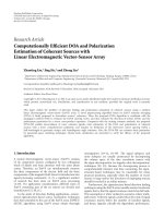
Figure 1: UWB multipath fading channel capacity with L = 4.
1
2
3
4
5
6
7
8
9
10
11
0 2 4 6 8 101214161820
m
= 0.65
m
= 1
m
= 2
m
= 3
Figure 2: UWB multipath fading channel capacity with L = 10.
From (29), the mean of W
MAI
can then be calculated as
E
W
MAI
= E
L
l=1
K
k=2
v
lk
a
lk
A
(k)
θ(Δ)
=
L
l=1
K
k=2
E
v
lk
E
a
lk
A
(k)
E
θ(Δ)
=
0
(30)
0
0.5
1
1.5
2
2.5
3
3.5
4
4.5
5
(Bits/s/Hz)
−5051015202530
L
= 2, m = 0.65
SNR (dB)
2PPM
4PPM
8PPM
16PPM
32PPM
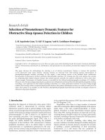
Figure 3: Capacity of a UWB system with PPM over a multipath
fading channel with L
= 2andm = 0.65.
0
0.5
1
1.5
2
2.5
3
3.5
4
4.5
5
(Bits/s/Hz)
−50 51015202530
SNRpBit (dB)
L
= 4, m = 2
2PPM
4PPM
8PPM
16PPM
32PPM
Figure 4: Capacity of a UWB system with PPM over a multipath
fading channel with L
= 4andm = 2.
and the variance of W
MAI
is
Var
W
MAI
= Va r
L
l=1
K
k=2
v
lk
a
lk
A
(k)
θ(Δ)
=
L
l=1
K
k=2
E
a
lk
A
(k)
2
E
θ
2
(Δ)
.
(31)
H. Zhang and T. A. Gulliver 7
0
0.5
1
1.5
2
2.5
3
3.5
4
4.5
5
(Bits/s/Hz)
0 5 10 15 20 25 30
Distance (m)
2PPM
4PPM
8PPM
16PPM
32PPM
Figure 5: Relationship between distance and channel capacity of a
UWB system with PPM over a multipath fading channel, L
= 2,
m
= 0.65, and n = 3.
0.5
1
1.5
2
2.5
3
3.5
4
4.5
5
(Bits/s/Hz)
−50 51015202530
SNR (dB)
2-PAM
4-PAM
8-PAM
16-PAM
32-PAM
Figure 6: Capacity of a UWB system with PAM over a multipath
fading channel with L
= 4andm = 0.65.
Given that
E
θ
2
(Δ)
=
E
sin
2
(WΔ/2)
(πΔ)
2
P
x
2πW
2
=
P
x
2πW
2
T
f
−T
f
sin
2
(WΔ/2)
(πΔ)
2
1
2T
f
dΔ
≈
P
x
2πW
2
1
π
2
1
2T
f
π
2
W
2
=
P
2
x
32Gπ
3
,
(32)
0
0.5
1
1.5
2
2.5
3
3.5
4
(Bits/s/Hz)
−50510152025
SNRpBit (dB)
L
= 4, m = 0.65, K = 200,
G
= 100, P
x
=−11 dBm
2PPM
4PPM
8PPM
16PPM
Figure 7: Capacity of a multiple access UWB system with PPM over
a multipath fading channel with L
= 4, m = 0.65, K = 200, G =
100, and P
x
=−11 dBm.
we can write the variance as
σ
MAI
= Va r
W
MAI
=
L
l=1
K
k=2
a
2
lk
P
2
x
32Gπ
3
E
g
, (33)
where G
= T
f
/T
p
is the processing gain of the UWB system.
Note that the approximation in (32) is based on the fact
that most of the energy of the Sinc function is located in
[
−T
f
, T
f
]. Hence the cross-correlator outputs of user 1’s
receiver can be modeled as independent Gaussian random
variables with distributions
r
j
∼N
L
l=1
a
l1
2
A
m
(1)
E
g
, σ
2
total
,
j = n
,
r
j
∼N
0, σ
2
total
,
j
/
= n,
(34)
where σ
2
total
=
L
l=1
K
k=2
(a
2
lk
P
2
x
/32Gπ
3
)E
g
+
L
l=1
a
l1
2
N
0
.
The equivalent SNR is
γ
=
L
l
=1
a
l1
2
A
m
(1)
2
E
g
L
l=1
K
k=2
a
2
lk
P
2
x
/32Gπ
3
E
g
+
L
l=1
a
l1
2
N
0
, (35)
which can be written as
γ
=
L
l
=1
a
l1
2
2
L
l=1
K
k=2
a
2
lk
P
2
x
/32Gπ
3
+
L
l=1
(a
l1
2
/SNR)
,
γ
=
L
l=1
|a
l1
2
2
3/
M
2
−1
L
l
=1
K
k
=2
a
2
lk
P
2
x
/32Gπ
3
+
L
l
=1
(a
l1
2
/SNR)
(36)
for PPM and PAM, respectively.
8 EURASIP Journal on Wireless Communications and Networking
0
0.5
1
1.5
2
2.5
3
3.5
4
(Bits/s/Hz)
−50 51015202530
SNR (dB)
G
= 100, K = 200,
L
= 4, m = 0.65
2-PAM
4-PAM
8-PAM
16-PAM
Figure 8: Capacity of a multiple access UWB system with PAM over
a multipath fading channel with L
= 4, m = 0.65, K = 200, G =
100, and P
x
=−11 dBm.
The instantaneous capacity for a multiple access UWB
system with PPM or PAM can be obtained by substituting
γ from (35)in(17)or(18), respectively. The channel
capacity can then be obtained by averaging the instantaneous
capacities over the joint PDF of a
l
.
5. NUMERICAL RESULTS
In this section, some numerical results are presented to
illustrate and verify the analytical expressions obtained
previously.
Figures 1 and 2 show the capacity of the multipath fading
UWB channel with continuous inputs and outputs with
L
= 2andL = 4, respectively. This shows that the capacity
increases as m increases, and L
= 4 can achieve a higher
capacity than L
= 2 for the same SNR. Note that the capacity
for L
= 4 is almost equal to the 1.5 m, L = 2capacity.
Figure 3 shows the capacity of a UWB system with PPM
over multipath fading channels, with L
= 2andm = 0.65,
while Figure 4 gives the capacity for L
= 4andm = 2.
Obviously, the larger L and m, the greater the capacity.
Figure 5 presents the relationship between reliable chan-
nel capacity and the communication range subject to FCC
Part 15 rules. The link budget model in (18) is applied and
the channel parameters are n
= 3, L = 2, and m = 0.65.
This shows that PPM can provide full capacity only within
2m in most cases. However, less than half of the capacity can
be achieved when the communication distance is extended
to 10m over a fading channel. In general, a UWB system
can only provide reliable transmission over very short or
medium ranges with the restriction of FCC Part 15 rules and
a multipath fading channel.
Figure 6 shows the capacity of PAM over a multipath
fading channel with L
= 4andm = 0.65. The capacity of
0.5
1
1.5
2
2.5
3
3.5
(Bits/s/Hz)
10
0
10
1
10
2
10
3
Number of user, SNR = 15 dB
L
= 2, m = 0.65
2PPM
4PPM
8PPM
16PPM
Figure 9: Relationship between channel capacity and number of
users for a multiple access UWB system with PPM over a multipath
fading channel, L
= 2, m = 0.65, G = 100, P
x
=−11 dBm, and SNR
= 15 dB.
a multiple access UWB system with PPM and PAM over a
multipath fading channel with L
= 4, m = 0.65, K = 200,
G
= 100, and P
x
=−11 dBm is shown in Figures 7 and 8,
respectively. The relationship between the number of users
and the capacity of a PPM UWB system is demonstrated in
Figure 9. This shows that the system can only achieve less
than half the capacity with 10 simultaneous active users.
6. CONCLUSIONS
The capacity of UWB PPM and PAM systems over multipath
fading channels has been studied from a SNR perspective.
The capacity was first derived for an AWGN channel and
then extended to a fading channel by averaging the SNR
over the channel random variables. Both single and multiple
user capacities were considered. Exact capacity expressions
were derived, and Monte Carlo simulation was employed for
efficient evaluation. It was shown that fading has a significant
effect on the capacity of a UWB system.
APPENDICES
A. CAPACITY OVER FLAT FADING CHANNEL
The channel capacity for a UWB system in a flat fading
channel can be obtained by letting L
= 1in(14):
C =
∞
0
log
2
1+γ
s
a
2
1
p
a
1
da
1
=
∞
0
log
2
1+γ
s
a
2
1
2
Γ(m)
m
Ω
1
m
a
2m−1
1
e
−ma
2
1
/Ω
1
da
1
.
(A.1)
H. Zhang and T. A. Gulliver 9
To simplify the expression, we substitute u = (m/Ω)a
2
,so
that (A.1)canbewrittenas
C =
1
Γ(m)
∞
0
log
2
1+
Ωγ
s
m
u
u
m−1
e
−u
du. (A.2)
By letting ρ
= m/Ωγ
s
,(A.2) can be simplified to
C =
1
Γ(m)
∞
0
log
2
1+
u
ρ
u
m−1
e
−u
du. (A.3)
B. EQUIVALENT SNR FOR A RAKE RECEIVER OVER
FREQUENCY-SELECTIVE FADING CHANNELS
A Rake receiver will process the received signal in an
optimum manner if the receiver has perfect channel state
information. The received signal (4) can then be written as
r(t)
=
L
l=1
a
2
l
δ
t −τ
l
(t)
X(t)+
L
l=1
a
∗
l
(t)δ
t −τ
l
(t)
w(t).
(B.1)
The equivalent SNR of (B.1)isgivenby
γ
L
=
w/2
w/2
G
X
( f )
L
l
=1
a
2
l
e
−j2πf(l−1)τ
2
df
w/2
w/2
G
W
( f )
L
l=1
v
l
a
l
e
−j2πf(l−1)τ
2
df
. (B.2)
Note that G
X
( f )isdefinedin(12), and
G
W
( f ) =
⎧
⎪
⎨
⎪
⎩
N
0
,wheref ∈
−
W
2
W
2
0, otherwise.
(B.3)
Equation (B.2) can then be written as
γ
L
=
γ
s
π
0
L
l=1
a
2
l
cos((l−1)u)
2
+
L
l=1
a
2
l
sin((l−1)u)
2
du
π
0
L
l
=1
v
l
a
l
cos((l−1)u)
2
+
L
l
=1
v
l
a
l
sin((l−1)u)
2
du
.
(B.4)
ACKNOWLEDGMENTS
This work is supported by National 863 Hi-Tech Research
and Development Program of China under Grant no.
2007AA12Z317 and Science & Technology Developing Pro-
gram of Qingdao, China under Grant 06-2-3-19-gaoxiao.
REFERENCES
[1] M. Z. Win and R. A. Scholtz, “Ultra-wide bandwidth time-
hopping spread-spectrum impulse radio for wireless multiple-
access communications,” IEEE Transactions on Communica-
tions, vol. 48, no. 4, pp. 679–691, 2000.
[2] D. Cassioli, M. Z. Win, and A. F. Molisch, “The ultra-wide
bandwidth indoor channel: from statistical model to simu-
lations,” IEEE Journal on Selected Areas in Communications,
vol. 20, no. 6, pp. 1247–1257, 2002.
[3] H. Zhang, T. Udagawa, T. Arita, and M. Nakagawa, “A
statistical model for the small-scale multipath fading charac-
teristics of ultrawide band indoor channel,” in Proceedings o f
IEEE Conference on Ultra Wideband Systems and Technologies
(UWBST ’02), pp. 81–85, Baltimore, Md, USA, May 2002.
[4] A. F. Molisch, “IEEE 802.15.4a channel model—final report,”
IEEE 802.15-04-0662-00-004a, November 2004.
[5] L. Zhao and A. M. Haimovich, “Capacity of M-ary PPM
ultra-wideband communications over AWGN channels,” in
Proceedings of the 54th IEEE Vehicular Technology Conference
(VTC ’01), vol. 2, pp. 1191–1195, Atlantic City, NJ, USA,
October 2001.
[6] L. Zhao and A. M. Haimovich, “The capacity of an UWB
multiple-access communications system,” in Proceedings of
IEEE Internat ional Conference on Communications (ICC ’02),
vol. 3, pp. 1964–1968, New York, NY, USA, April-May 2002.
[7] H. Zhang, W. Li, and T. A. Gulliver, “Pulse position amplitude
modulation for time-hopping multiple-access UWB commu-
nications,” IEEE Transactions on Communications, vol. 53,
no. 8, pp. 1269–1273, 2005.
[8] H. Zhang and T. A. Gulliver, “Biorthogonal pulse position
modulation for time-hopping multiple access UWB com-
munications,” IEEE Transactions on Wireless Communications,
vol. 4, no. 3, pp. 1154–1162, 2005.
[9] H. Zhang and T. A. Gulliver, “Performance and capacity of
PAM and PPM UWB time-hopping multiple access commu-
nications with receive diversity,” EURASIP Journal on Applied
Signal Processing, vol. 2005, no. 3, pp. 306–315, 2005.
[10] J. R. Foerster, “Ultra-wideband technology for short- or
medium-range wireless communications,” Intel Technology
Journal, vol. 5, no. Q2, pp. 1–11, 2001.
[11] F. Zheng and T. Kaiser, “On the evaluation of channel
capacity of multi-antenna UWB indoor wireless systems,”
in Proceedings of IEEE International Symposium on Spread
Spectrum Techniques and Applications (ISSSTA ’04), pp. 525–
529, Sydney, Australia, August-September 2004.
[12] H. Zhang and T. A. Gulliver, “Closed form capacity expres-
sions for space time block codes over fading channels,” in
Proceedings of IEEE International Symposium on Information
Theory (ISIT ’04), p. 411, Chicago, Il, USA, July 2004.
[13] G. Durisi and G. Romano, “On the validity of Gaussian
approximation to characterize the multiuser capacity of
UWB TH PPM,” in Proceedings of IEEE Conference on Ultra
Wideband Systems and Technologies (UWBST ’02), pp. 157–
161, Baltimore, Md, USA, May 2002.